

Page 1
Paxar
Monarch
Printers
9825
9850
9855
9860
TC9850ENOI Rev. AD 3/03 ©2001 Paxar Americas, Inc. All rights reserved.
Page 2

Each product and program carries a respective written warranty, the only
warranty on which the customer can rely. Paxar reserves the right to make
changes in the product and the programs and their availability at any time and
without notice. Although Paxar has made every effort to provide complete and
accurate information in this manual, Paxar shall not be liable for any omissions
or inaccuracies. Any update will be incorporated in a later edition of this
manual.
©2001 Paxar Americas, Inc. All rights reserved. No part of this publication
may be reproduced, transmitted, stored in a retrieval system, or translated into
any language in any form by any means, without the written permission of
Paxar Americas, Inc.
Trademarks
7410, 9800, 9825, 9850, 9855, 9860, and PaxarNet are trademarks of Paxar Americas, Inc.
Monarch is a registered trademark of Monarch Marking Systems, Inc.
Paxar is a trademark of Paxar Corporation.
Centronics is a registered tradmark of Centronics Data Computer Corporation.
Microsoft and MS-DOS are registered trademarks of Microsoft Corporation.
Windows and NT are registered trademarks of Microsoft in the U.S. and other countries.
Hewlett-Packard is a registered trademark of Hewlett-Packard Company.
HP Jet Admin, HP JetDirect, and HP Web Jet Admin are trademarks of Hewlett-Packard Company.
Novell and NetWare are registered trademarks of Novell, Inc., in the United States and other countries.
Other products are trademarks or registered trademarks of their respective holders and should be noted as
such.
Paxar Corporation
170 Monarch Lane
Miamisburg, OH 45342
Page 3

Regulatory Compliance
Paxar RF products are designed to be compliant with the rules and regulations in the locations
into which they are sold and will be labeled as required. The majority of Paxar RF devices are
type approved and do not require the user to obtain license or authorization before using the
equipment. Any changes or modifications to Paxar equipment not expressly approved by Paxar
could void the user authority to operate the equipment.
FCC RF Exposure Guidelines
To comply with FCC exposure requirements, antennas that are mounted externally at remote
locations or operating near users at stand-alone desktop of similar configurations must operate
with a minimum separation distance of 20 cm from all persons.
Declaration of Conformity for RF Exposure:
The radio module has been evaluated under FCC Bulletin OET 65C and found compliant to the
requirements as set forth in CFR 47 Sections 2.1091, 2.1093, and 15.247 (b) (4) addressing RF
Exposure from radio frequency devices.
Radio Frequency Interference Requirements
This device complies with Part 15 of the FCC Rules. Operation is subject to the following two
conditions: 1) this device may not cause harmful interference, and 2) this device must accept any
interference that may cause undesired operations.
CAUTION:
The Part 15 radio device operates on a non-interference basis with other devices operating at this
frequency when using the listed antenna.
Collocation Statement:
This device must not be collocated with any other antenna or transmitters.
Page 4

Radio Frequency Interference Requirements - Canada
This device complies with RSS 210 of Industry & Science Canada. Operation is subject to the
following two conditions: (1) this device may not cause harmful interference and (2) this device
must accept any interference received, including interference that may cause undesired
operation.
This Class A digital apparatus meets the requirements of the Canadian Interference-Causing
Equipment Regulations.
Cet appareil numérique de la Classe A especte toutes les exigencies du Reglement sur le
Materiél Brouilleur du Canada.
European Economic Area
The European variant is intended for use throughout the European Economic Area, however
authorization for use restricted as follows:
European standards dictate maximums radiated transmit power of 100 mW EIRP and frequency
range 2.400 –2.4835 GHz.
France, the equipment is to be restricted to the 2.4465 – 2.4835 GHz frequency range.
Belgium outside, the equipment is to be restricted to the 2.460 – 2.4835 GHz frequency range.
Operation in Italy requires a user license.
Page 5

TABLE OF CONTENTS
Installing the Print Server Hardware................................................... 1-1
System Requirements........................................................................ 1-1
Network Protocols Supported ............................................................. 1-2
Checking the Print Server Hardware ................................................... 1-3
Verifying Successful Installation......................................................... 1-3
Verifying Successful Installation......................................................... 1-4
Sample Test Page .......................................................................... 1-6
Configuring the 802.11b and IP Settings............................................. 2-1
Configuring the Print Server............................................................... 2-1
Before You Begin .............................................................................. 2-1
Installing the Software....................................................................... 2-2
Management Methods ......................................................................... 3-1
WP-Admin Utility............................................................................... 3-1
XAdmin32 Utility ............................................................................... 3-1
Web Browser .................................................................................... 3-1
PaxarNet Console ............................................................................. 3-2
HP JetAdmin Utility ........................................................................... 3-2
HP Web JetAdmin Utility.................................................................... 3-3
Microsoft Windows Network Configuration...................................... 3-3
Installing ExtendNet Connect ............................................................. 3-3
Additional Windows Configuration Methods ......................................... 3-4
UNIX Network Configuration .............................................................. 3-4
Berkeley UNIX Host Configuration ...................................................... 3-5
Sun Solaris Configuration ............................................................... 3-6
i
Page 6

HP/UX Configuration ......................................................................... 3-8
IBM AIX Configuration ....................................................................... 3-9
Configuration on Other Systems......................................................... 3-9
Troubleshooting ................................................................................. 4-1
General Troubleshooting Information .................................................. 4-1
Troubleshooting Wireless Configuration Problems ............................... 4-4
Troubleshooting Network Configuration............................................... 4-5
Wireless Server Configuration Screen Fields....................................... 4-5
Loading the Firmware ........................................................................ 4-9
Software Versions ............................................................................. 4-9
Technical Support - Where to Get Help ............................................. 4-10
Telnet Console Commands................................................................. A-1
General Commands........................................................................... A-3
802.11b Wireless Commands ............................................................. A-7
TCP/IP Commands ............................................................................ A-8
SNMP Commands ........................................................................... A-10
ii
Page 7

INSTALLING THE PRINT
1
SERVER HARDWARE
The Paxar Monarch 7410 Print Server lets you communicate with
Paxar Monarch printers on an 802.11b wireless network. You can use
the print server in ad-hoc (peer-to-peer) or infrastructure (access point)
wireless mode. The print server operates at speeds of up to 11 Mbps on any
IEEE 802.11b wireless compatible network.
The Paxar Monarch 985x printers can be used on
the Paxar Monarch 9876 Mobile Printing Station for
portable wireless communication.
In addition, the wireless print server includes a unique dual-mode built-in
wired Ethernet connection. What does this mean? No more production
slowdowns in poor coverage areas; when the RF net is down; or when RF
traffic is heavy. Simply move the printer and/or mobile printing station to the
nearest Ethernet jack, plug it in, and the print server automatically switches
to wired Ethernet mode! Unplug the Ethernet cable and it automatically
switches back to RF!
Follow the instructions in this manual to configure the wireless print server
for your printer. For more information and software downloads, see Chapter
4, “Troubleshooting.”
System Requirements
To use the print server for printing from a wireless network, you need an
802.11b wireless network. The wireless network consists of either of the
following:
♦ An 802.11b wireless enabled PC printing straight to the printer (Ad-Hoc
or Peer-to-Peer Mode).
♦ An 802.11b wireless Access point allowing wireless and wired Ethernet
enabled computers to print to the print server (Infrastructure Mode).
Installing the Print Server Hardware 1-1
Page 8

To configure and print, you need the following:
1. The MAC address from the label of the print server (for example:
004017023F96).
2. The following information from your wireless network administrator:
♦ Wireless Mode (Infrastructure or Ad-Hoc)
♦ The SSID (service set identifier) for your wireless network.
♦ If you are using TCP/IP (recommended for Windows
Networks) and are not connected to a DHCP server (for
obtaining an IP Address automatically), you need a unique
IP Address for the wireless print server (for example:
192.168.1.14) and a subnet mask. If the print server is not
on the same IP subnet as the computers you are printing
from, you need a subnet mask. A router (default gateway)
address is optional.
Network Protocols Supported
♦ TCP/IP:
LPD/LPR
Raw TCP/IP (port 9100 or any chosen port)
NetBIOS over IP (with SMB)
♦ TELNET
♦ WINS
♦ DHCP
1-2 Installing the Print Server Hardware
Page 9
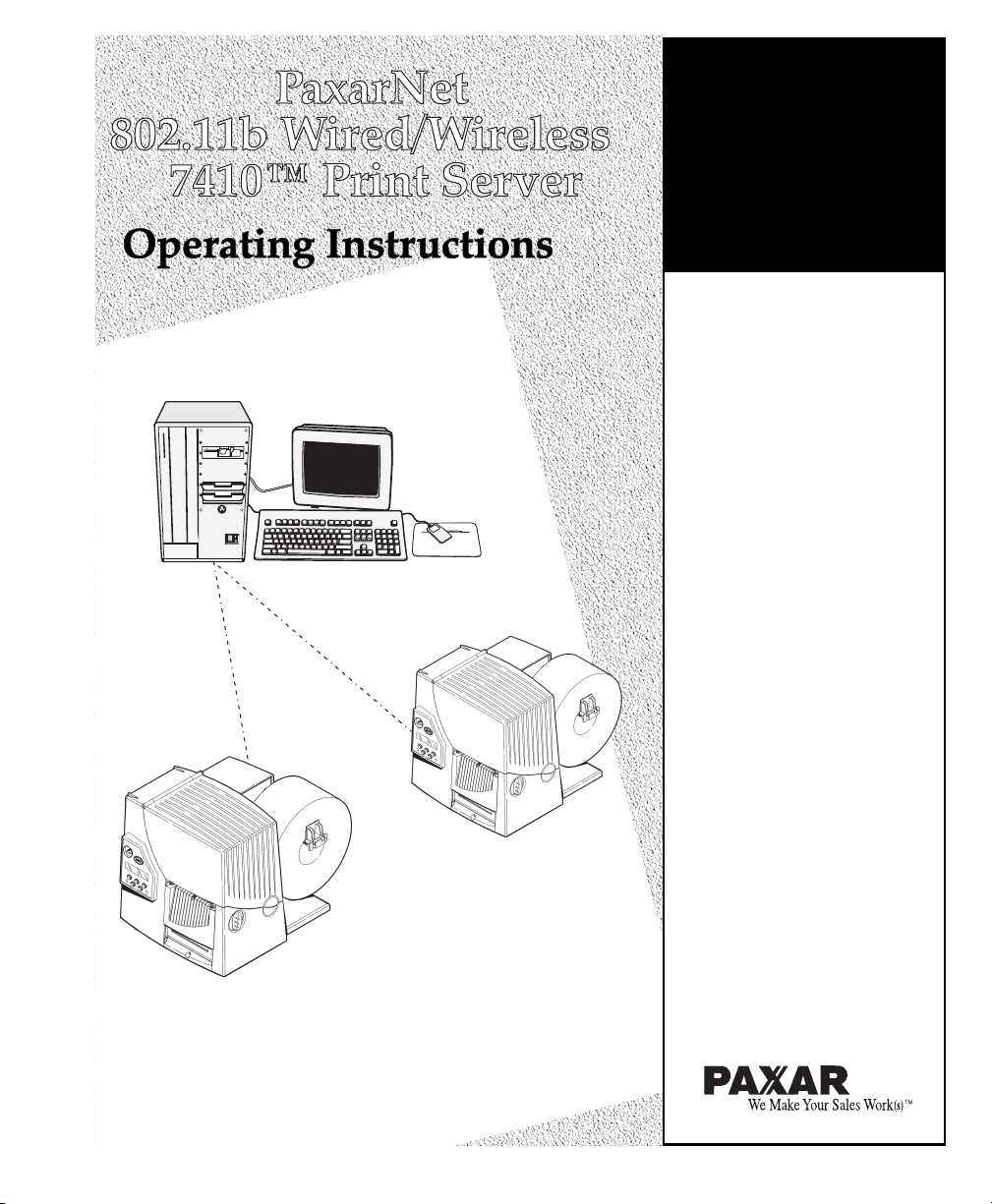
Checking the Print Server Hardware
The print server comes preinstalled and tested in your printer. Do not plug
any cables into the parallel port when using the print server. A printer with
this print server cannot use the parallel port. However, the serial port is still
active.
Antenna
Test/Reset Button
Serial
Port
985x Plastic Cover Printer
Installing the Print Server Hardware 1-3
Page 10
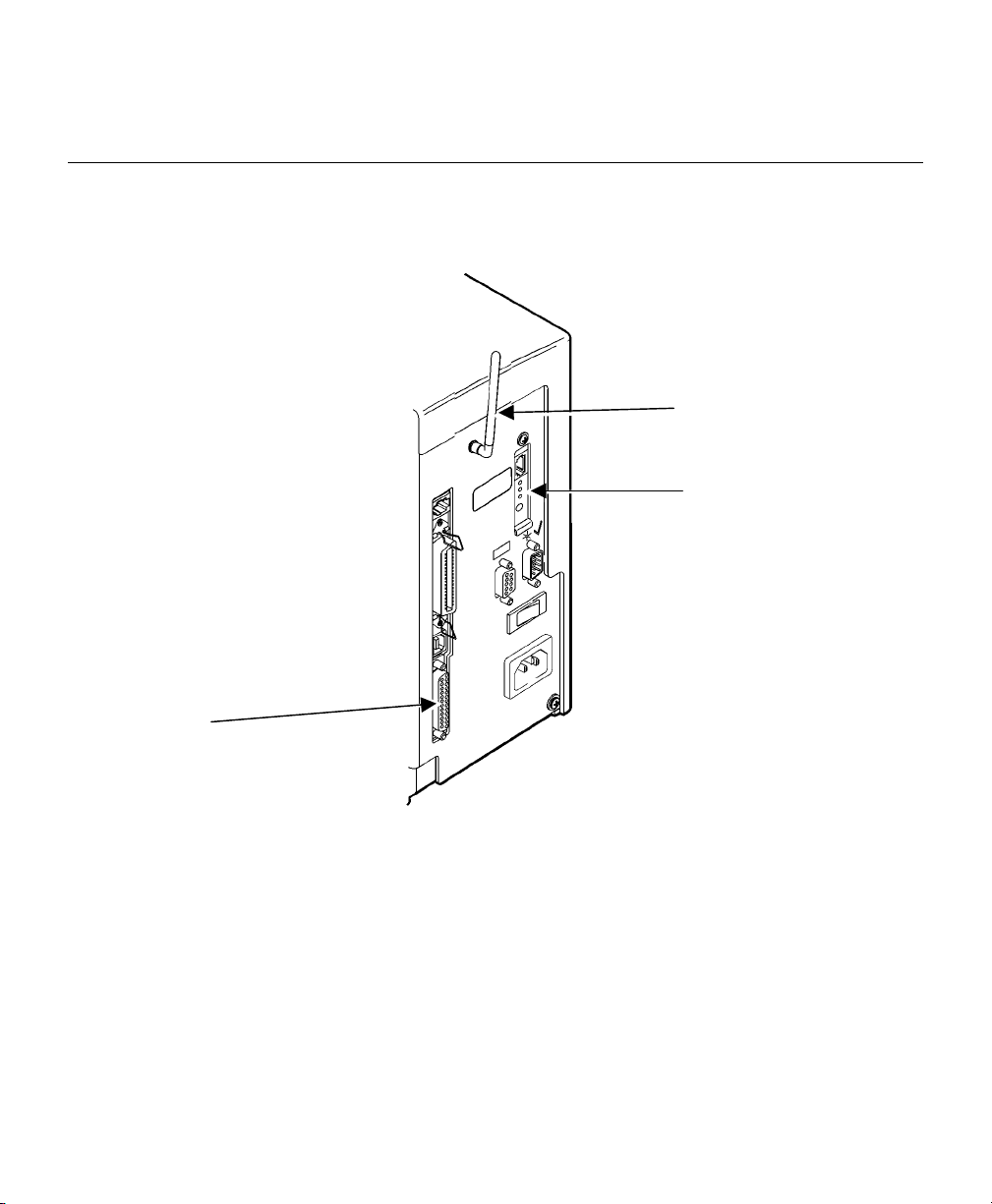
Antenna
Test/Reset Button
Serial
Port
9860 Printer
Verifying Successful Installation
When the print server is turned on, it goes through the following startup
sequence:
♦ It runs through a set of power-up diagnostics for a few seconds. The
green light comes on when the unit is turned on, then the green light
turns off. The yellow light comes on solid when an Ethernet link (wired)
is established. The red light comes on solid when a wireless link is
established. The green light blinks during network activity.
1-4 Installing the Print Server Hardware
Page 11

Test/Reset Button Press this button down for less than 5 seconds to
print a test page on the printer. The test page
shows the current wireless and network settings of
the print server. See “Sample Test Page” for more
information. If the test page does not print, see
Chapter 4, “Troubleshooting.”
Press this button down for more than 5 seconds
while turned on to reset the print server to its
factory default parameters.
LED Status Indicators The green light comes on when the unit is turned
on, then the green light turns off. The yellow light
comes on solid when an Ethernet link (wired) is
established. The red light comes on solid when a
wireless link is established. The green light blinks
during network activity.
Antenna A rugged 802.11b compatible antenna, mounted on
the back of plastic-cover printers or on the top of
metal-cover printers.
Installing the Print Server Hardware 1-5
Page 12
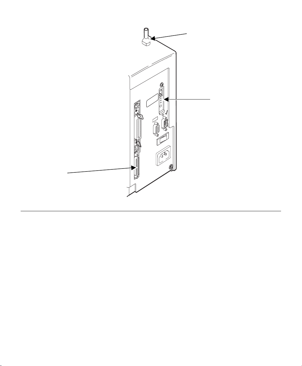
Sample Test Page
The test page is best displayed using 4” wide by 6” long labels. If the label
is too small, some information may print outside the label edges.
PAXAR
------------------ PaxarNet Print Server Status -------------
Firmware
versions
MAC
address
TCP/IP
settings
Set
method
should
match
defined
Method
Transmit packet fail 0
PaxarNet Network Adapter-PLUS
FW Ver. CLM -3.99 (2003.02.19) Netware Retries: 0
Boot Ver. 7.3 Frame type Network Count
Ethernet: 00-40-17-0d-20-77 EN_11 00000302 9609
Node name: MON_002077 EN_802.2 Unknown 2931
EN_802.3 00000302 109314
EN_SNAP Unknown 3142
Active Services:
MON_002077_P1 AppleTalk Name:
BINARY_P1 MON_002077_P1_AT
TEXT_P1 AppleTalk Zone:
POSTSCRIPT_P1
PCL_P1
NetBIOS Computer Name:
MON_002077_S1 MON_002077
BINARY_S1 NetBIOS Domain:
TEXT_S1 MSBG_ENG
POSTSCRIPT_S1 Primary WINS server
PCL_S1 0.0.0.0
Secondary WINS server
0.0.0.0.
TCP/IP Enabled
Netware Enabled WiFi Channel: 11
AppleTalk Enabled WiFi SSID: abc123
POP3 Disabled WiFi Mode: INFRASTRUCTURE
DLC Enabled WiFi Speed: 11
NetBIOS/IP Enabled WiFi WEP: DISABLED
NetBEUI Enabled WiFi Signal Quality: 75%
LAT Disabled Actual SSID:
Banyan Disabled
Wired/Wireless: WIRED
IP address 10.1.88.155
Subnet mask 255.255.0.0 NETWORK STATISTICS
IP Gateway 10.1.110.254 Packets Received 428129
(set manually) Bytes Received 093759
Boot method STATIC Bad Packets Received 0
Boot tries 3 Receiver error mask 0000
Receiver overruns 79
Netware Status: No server enabled Packets Transmitted 2807
Mode: Queue Server Bytes Transmitted 257578
Server Name: Packet Collisions 22
WiFi settings
Security
setting
Should be at
least 60%
Actual SSID
should match
WiFi SSID
How print
server is
communicating
1-6 Installing the Print Server Hardware
Page 13

CONFIGURING THE 802.11B
2
AND IP SETTINGS
Configuring the Print Server
There are three basic steps required to configure print server:
1. Configuring the 802.11b settings for wireless usage. To operate on an
802.11b network, you must set the wireless (ad-hoc or infrastructure),
SSID, channel, data rate and WEP encryption. All nodes of a wireless
network need to have the same settings in order to communicate with
each other.
2. Configuring the IP address settings. You need to set the IP address,
subnet mask, and router address if you are using TCP/IP, NetBIOS IP,
or if you want to use the Web Browser management utility.
3. Configuring the print server for operation with the network operating
systems. Configure the print server to print using one or more network
operating systems (for example, Windows NT/2000, NetWare, etc.).
Before You Begin
Make sure that you have properly configured your computer for
communication on a wireless network. If you are connecting to the device
through an access point, make sure your computer is in infrastructure mode
and it is associated with the access point. If you are connecting directly to
the device without an access point, you should be in ad-hoc mode. See the
documentation for your wireless adapter for instructions.
NOTE: If your wireless adapter includes an option for 802.11 Ad-hoc, you
must select it if you want to use the printer in ad-hoc mode. If it
doesn’t include this option, select Ad-hoc Computer-to-Computer, or
whatever mode your adapter uses to communicate on a wireless
network without an access point.
Configuring the 802.11b and IP Settings 2-1
Page 14

If you are using WEP (Wired Equivalent Privacy) encryption on your wireless
network, you will need to temporarily disable WEP on your PC in order to
configure the print server. If you are using an access point with WEP
enabled and it does not allow non-wep clients to communicate with other
non-wep clients, then you will also need to temporarily change the wireless
mode of your computer to Ad-hoc (802.11) mode.
NOTE: If no computers on your network can be set to Ad-hoc mode, you
need to temporarily disable WEP on your access point. When you
are done configuring the print server, you can re-enable WEP on
your computer and change the wireless mode back if necessary.
♦ If you are using TCP/IP, note your computer’s IP address. The print
server needs to be on the same IP segment as the other nodes on your
network in order to communicate.
♦ If you are using infrastructure mode, make sure you have a good signal
between your computer and the access point. Most wireless adapters
have a utility that shows the wireless signal strength. See your wireless
adapter’s documentation for details.
♦ If you are using a home gateway or router, you should configure the print
server from a PC on the same network segment that you want the print
server to be on.
Installing the Software
The following operating systems are supported: Microsoft Windows 95,
98, ME, NT 4, 2000, and XP.
Follow these steps to install the WP-Admin software and configure the print
server.
1. Insert the Wireless Configuration CD-ROM into your PC.
2. Click on Install PaxarNet Utilities, then click on Install PaxarNet
Configuration Utilities and Printing Software.
NOTE: If you are using Windows and don’t have the Java Runtime installed
on your system, you will be prompted to install it, click Continue.
3. Follow the on-screen instructions for installing the utility. When WPAdmin starts, you will see the WP-Admin Wireless Server Search screen.
2-2 Configuring the 802.11b and IP Settings
Page 15

4. Click START to begin searching for print servers. WP-Admin gets the
information from the print server(s) and lists the Server Name and
Ethernet Address (which should correspond with the label on the back of
the print server). It might take a minute or two for the print server to
show up, especially if you have a large wireless network. The default
name of the print server is XCD_xxxxxx, where xxxxxx is the last six
digits of the Ethernet (MAC) address (for example, XCD_08B2C7).
NOTE: If you do not see the print server in the list, hold down the button for
more than 5 seconds to reset it to factory defaults and try the search
again. If you still do not see it, see Chapter 4, “Troubleshooting.”
5. When you see the print server you want to configure in the list, highlight
it and click Configure. If you are using DHCP, wait until the print server
gets an IP Address from the DHCP server and is updated on the search
screen before configuring (the IP address changes from the default
10.1.85.1 to a new value).
NOTE: If the wireless signal is less than 50% on the search screen, printing
performance could be affected. To improve the signal strength, try
moving the print server closer to the computer or access point and
away from other radio devices such as Bluetooth wireless devices,
microwave ovens, or 2.4 gigahertz cordless phones.
6. You will be prompted for the configuration password (the default
password is access), type in the password and click OK to continue.
The Wireless Server Configuration screen comes up.
NOTE: If you are having trouble configuring a print server, click Cancel to
get back to the Search screen, click Clear to clear the list of print
servers, and start again from step 4 above.
7. The settings of the print server you selected in the Wireless Server
Search screen will be displayed. Many of the fields are automatically
configured to match the network being used, so you probably do NOT
need to change the Wireless Mode, RF Channel, SSID, and Data Rate
settings unless you want to want to change the print server to a different
wireless network.
Configuring the 802.11b and IP Settings 2-3
Page 16

♦ If your network uses WEP encryption, you need to enable WEP and enter
the appropriate WEP key(s). Contact your system manager to determine
what information you need.
♦ If you are using TCP/IP and you do not have a DHCP server (see note
below), you will need to manually assign a valid IP Address, Subnet
Mask, and Gateway and then set the Boot Method to Static.
8. When you are done configuring, click OK.
NOTE: If you are using DHCP on your network, the print server may have
acquired valid IP settings at this point and no further configuration is
necessary. This might work well if your DHCP server allows the print
server to keep this address permanently, but in most cases, you
should use a static address outside the range reserved for DHCP
(See your DHCP server documentation for details). This is because
when you configure your printer port, it goes to a static IP address.
Your print server should be configured correctly at this point.
2-4 Configuring the 802.11b and IP Settings
Page 17

MANAGEMENT METHODS
There are a variety of ways to configure and monitor the print
server. These methods are: WP-Admin, XAdmin32, Web Browser, PaxarNet
Console, HP JetAdmin, HP Web JetAdmin, or Telnet. For Telnet/console
mode information, see Appendix A, “Telnet Console Commands.”
3
WP-Admin Utility
This utility runs on Windows computers, and is used for initial configuration
of the print server and allows you to set the wireless settings as well as the
basic network settings including TCP/IP.
See the previous chapter “Configuring the 802.11b and IP Settings” for
detailed instructions.
This utility can be downloaded from our web site, see Chapter 4,
“Troubleshooting.” After initial installation, this utility can be run from the
START menu under START>Programs>Troy Group>Etherwind>WP-Admin.
The default password is ACCESS.
XAdmin32 Utility
This utility runs on Windows computers and is used for advanced
configuration of the print server; it allows you to configure for Netware,
TCP/IP, and more. It is a 32-bit graphical utility that is compatible with
Windows PC’s running TCP/IP or IPX/SPX Protocols.
This utility can be downloaded from our web site, see Chapter 4,
“Troubleshooting.” After initial installation, this utility can be run from the
START menu under START>Programs>Troy Group>Etherwind>XAdmin32.
The default password is ACCESS.
Web Browser
This utility allows the user to configure the print server with a standard web
browser like Netscape Navigator or Microsoft Internet Explorer. No
additional software is needed on the system. It can be used on any system
that supports web browser capabilities.
Management Methods 3-1
Page 18

Simply type the IP address into your web browser address bar to connect.
The default password is ACCESS.
NOTE: Both the print server and the PC must be configured with an IP
address and your browser must be configured to work across a LAN
in order to use a Web Browser.
PaxarNet Console
This is a command-line oriented console that contains features not available
through WP-Admin, Xadmin32 or a Web Browser. The default password is
ACCESS.
The console can be accessed via:
♦ TELNET
♦ Web Browser
NOTE: Enter the IP address in the browser. When prompted to enter
password, type ACCESS. On the network configuration main menu,
select Console. The screen allows you to enter console commands.
See Appendix A, “Telnet Console Commands,” for more information.
HP JetAdmin Utility
This HP Windows-based utility (works transparently with JetAdmin) can be
downloaded from the HP web site (http://www.hp.com).
NOTE: The print server will not appear in the list of configured servers
unless TCP/IP or IPX is running on the computer.
3-2 Management Methods
Page 19

HP Web JetAdmin Utility
This HP utility for Windows NT Advanced Server and Windows 2000 can be
downloaded from the HP web site (http://www.hp.com). Once it is installed, a
web browser on any computer that has access to the Windows NT/2000
server may be used to access the print server.
Microsoft Windows Network Configuration
The print server includes the easy-to-use ExtendNet Connect IP Monitor
software for printing from Windows computers over an 802.11b wireless link.
This software creates a network port on the Windows system, which acts like
a normal parallel port. As a result, it works transparently with any standard
Windows printer driver and application program. Because this software uses
the industry-standard TCP/IP protocol, it can be used with IP routers and
other IP-based equipment.
Installing ExtendNet Connect
1. Install the ExtendNet Connect IP Port Monitor by inserting the CD,
selecting Install PaxarNet Utilities, then Install ExtendNet Connect Port
Monitor. Follow the on-screen instructions to complete this installation.
2. Install the printer driver software according to the documentation for the
printer.
3. Click the Windows Start button, select Settings, and then Printers.
4. Right-Click on the printer you wish to associate with the network port,
and select Properties.
5. If you are using Windows NT/2000/XP, go to the Ports tab. If you are
using Windows 95/98/ME, go to the Details tab.
6. Click on Add Port.
Management Methods 3-3
Page 20

7. If you are using Windows NT/2000/XP system, highlight Paxar Group
ExtendNet Connect IP Monitor, and click New Port.
If you are running Windows 95/98/ME, select Other, highlight Paxar
Group ExtendNet Connect IP Monitor, and click OK.
8. The search will begin for available print servers, highlight the print
server you would like to create the port for, and click ADD.
9. Make sure the port you created is chosen and click Apply.
You are now ready to print.
Additional Windows Configuration Methods
The print server is also compatible with other methods of printing from
Windows. These include the Standard TCP/IP Port option in Windows
2000/XP, and the LPR Port option in Windows NT that are built into the
operating system.
UNIX Network Configuration
The print server appears to the network as a UNIX host computer with a
unique IP address running the line printer daemon (lpd) protocol. As a
result, any host computer that supports the Berkeley remote-LPR command
can spool jobs to the print server without the need for any special software
on the host computer.
NOTE: Before configuring a UNIX print queue, the print server must have a
valid IP address.
3-4 Management Methods
Page 21

Berkeley UNIX Host Configuration
Berkeley UNIX host computers include Linux, Digital Equipment Corporation
Digital UNIX, OSF/1, and ULTRIX; Compaq Tru64 UNIX; SunOS (not
Solaris), SCO UNIX; and many others. Sun Solaris, HP/UX, IBM AIX users
should skip to the appropriate sections later in this manual.
♦ Do not use the Linux X-Windows graphical user interface printer
configuration utility, because it does not work with Paxar print servers.
Instead, Linux users should follow the configuration steps listed in this
section.
♦ SCO UNIX users should use the rlpconf command to create a printer and
automatically configure the /etc/printcap file (you will still need to edit the
/etc/hosts file). Enter the print server's service name (XCD_xxxxxx_P1)
as the name of the printer (refer to the print server self-test for the exact
name of this service), and enter the name of the print server that you
assigned in the /etc/hosts file as the remote host name; note that
because this name must be unique for each printer, we recommend using
the XCD_xxxxxx_P1 service instead of the normal BINARY_P1 service.
1. Edit the /etc/hosts file: (or equivalent local host table). For example:
192.189.207.33 xcdprinter
2. Edit the printcap file: An example of a typical entry in the printcap file is:
PaxarPrinter:\
:lp=:\
:rm=XCD:\
:rp=BINARY_P1:\
:sd=/usr/spool/lpd/PaxarPrinter:
"PaxarPrinter" is the queuename.
"XCD" matches the name in the hosts file.
"BINARY_P1" is the print server's service name.
NOTE: Use TEXT_P1 instead of BINARY_P1 for text files.
"sd" is the spool directory.
Management Methods 3-5
Page 22

3. Create the spool directory: The lpd spool directory is usually located in
the /usr/spool directory. To create a new spool directory, use the mkdir
command; for example:
mkdir /usr/spool/lpd/PaxarPrinter
4. Print using the standard lpr command:
lpr –PPaxarPrinter filename
5. For AT&T based UNIX systems, such as SCO, use the standard lp
command:
lp –dPaxarPrinter filename
Sun Solaris Configuration
To use a print server with Sun Solaris, first use the Host Manager in the
Admintool utility to add the print server IP address and name to the
/etc/hosts file.
1. Click on None - Use /etc files on host
2. Click on Apply
3. Click on Edit and then Add Host
4. Enter the print server name as the Host Name (this name is anything you
want, but should not have an "_" character in it).
5. Enter the IP address and Ethernet address of the print server (the
Ethernet address has the format aa:bb:cc:dd:ee:ff)
6. Click Add and then close the Host Manager windows
3-6 Management Methods
Page 23

7. Then use the Printer Manager in the Admintool utility under Open
Windows as follows:
Select Edit
Select Add
Select Add Access to Remote Printer
At the PrinterName prompt, type any desired name for the print queue
At the Printer Server prompt, type:
name\!servicename
(for example, PaxarPrinter\!BINARY_P1), where:
name matches the print server name as entered in the host’s table.
servicename is the print service name. For binary graphics files use
the service BINARY_P1; for text files use the service TEXT_P1.
8. Make sure that the Print Server OS is set to BSD (this is the default
setting).
9. Select Add.
10. To print, use the standard lp command; for example:
lp –dPaxarPrinter filename
NOTES:
♦ We recommend using the /etc/hosts file for the printer name rather than
NIS or other name services.
♦ Due to a bug in the Sun lpd implementation on Solaris 2.4 and earlier
releases, may cause problems printing very long print jobs. The
workaround is to configure the print server as an HP JetDirect card using
the HP JetAdmin for UNIX software.
♦ Solaris print queues can also be configured from the UNIX shell using the
lpadmin command.
Management Methods 3-7
Page 24

HP/UX Configuration
To configure a print server using HP/UX 10.x, use the same program and
these steps:
1. When you get a list of options, select Printers and Plotters.
2. Select LP Spooler.
3. Select Printers and Plotters.
4. Select Actions and then Add Remote Printer/Plotter.
5. Enter any name as the Printer Name (this will be the name of the print
queue).
6. Enter the IP address of the print server as the Remote System Name.
7. Enter the desired print server service name (BINARY_P1 for binary files
or TEXT_P1 for text files) as the Remote Printer Name.
8. Check the box next to Remote Printer is on BSD System.
9. You may accept the default values for the remaining items.
10. Click OK to configure the printer.
11. You should now be able to print using the lp -d command with the printer
name.
NOTES:
♦ The configuration for HP Distributed Print Services and for earlier
versions of HP/UX is slightly different.
♦ The print server can also be configured as a JetDirect card using HP/UX.
To do this, you will need the HP UNIX Host Printing Software (part of
HP's JetAdmin for UNIX).
3-8 Management Methods
Page 25

IBM AIX Configuration
To configure a print server on IBM AIX 4.x, use the SMIT program as follows:
1. Enter smit and select Devices.
2. Select Printer/plotter.
3. Select Manage remote printer subsystem.
4. Select Client services.
5. Select Remote printer queues.
6. Select Add a remote queue. Enter the following remote queue settings:
♦ Name of queue to add (user selectable).Activate the queue
(Yes).
♦ Destination host (print server’s IP address; or if you have
configured the /etc/hosts file, use the name of the print
server that you specified in that file).
♦ Name of queue on remote printer BINARY_P1 for binary
files or TEXT_P1 for text files).
♦ Name of device to add (user selectable; for example lp0).
7. You should now be able to print using the normal lp -d command.
NOTES:
♦ The configuration for earlier versions of AIX is slightly
different. Refer to the Administrator's Manual on the CDROM for details.
♦ The print server can also be configured as a JetDirect card
using AIX. To do this, refer to your AIX documentation.
Configuration on Other Systems
The print server can be used with any computer system that supports the
lpr/lpd protocol or HP JetDirect (port 9100 is the default; however, it can be
reconfigured). Refer to the system’s documentation to configure lpr/lpd or
JetDirect print queues.
Management Methods 3-9
Page 26

3-10 Management Methods
Page 27

TROUBLESHOOTING
First, make sure the printer is operating properly:
1. Is the printer online and does it have supplies?
2. If the printer is working correctly, test the connection between the printer
and the print server by pushing the test button on the back of the printer
for less than 5 seconds.
3. If the test page does not print, try resetting the print server to factory
defaults by holding the test button for more than 5 seconds.
4
General Troubleshooting Information
Use the following information if your 7410 print server is not operating
properly.
1. Verify that the printer is turned on.
If the printer is on a Paxar 9876 Mobile Printing Station (cart), the
cart power AND the printer must be turned on. The print server does not
function when the printer is turned off.
2. Verify the print server is functioning.
When the printer is turned on, the print server goes through the following
startup sequence:
It runs through a set of power-up diagnostics for a few seconds. If
the print server is operating properly, all three LEDs blink
momentarily and then go out. Then, the LEDs come on to indicate
the following activity:
Yellow LED = Ethernet Link
Green LED = Activity
Red LED = Wireless Link
3. Print a test label (see sample on last page).
Press the print server button for about a second and a label should print.
Troubleshooting 4-1
Page 28

Use 6-inch long supply. If you are using supply that is shorter than 6
inches long, temporarily change your supply type to “continuous” to
print the entire test label. After printing the test label, change your
supply type to your previous setting.
If a label does not print, check the printer's display to see if it shows
a receiving status. If so, press Escape to exit receiving mode. Once
you see “Online Ready” on the display, print a test label again. If
this does not print or the printer does not display “Online Ready,” the
unit is locked up. Turn off the printer, wait fifteen seconds and then
turn it back on.
If the printer displays “Online Ready,” but is not printing, verify that
the parallel port settings did not change. The Parallel Port setting
should be “Internal” and the Mode setting should be “IEEE1284”.
(From the Main Menu, select Setup, Port Settings, Parallel Comm.,
Port and Mode.)
4. On the test label, verify your IP and WiFi settings. If using an Ethernet
cable, the “Wired/Wireless:” value should be “WIRED”. If using RF, the
setting should be “WIRELESS”.
Check the “Actual SSID” and the “WiFi Sig Qual”. Is the actual SSID
correct? Is the signal quality greater than zero? If the signal quality
is 0, you lost connection with the access point. If it is very low, you
may be experiencing interference or are very close to being out of
range or an access point. A value of 100 is the best you can have
for signal quality. You can probably operate at a minimum of 60, but
the number of retries is likely to increase.
5. Ping the printer.
If you can ping the printer, it is at least "seen" on the network. If you
cannot ping the printer, then ping every device in the path to the printer access points, routers, etc. If you can ping every device but the printer,
the printer needs to be turned off and back on. If some device in the
path to the printer cannot be pinged, that device needs attention.
ping <ip address> (i.e. ping 10.1.88.150)
6. Telnet to the printer.
Once you have verified connectivity, telnet to the printer using port 23
(console). This gives you access to console operation of the printer.
4-2 Troubleshooting
Page 29

Press Enter (on your host) to get the “#” prompt and enter “access” as
the password. Press Enter to by-pass the user name. Once here, you
have verified operation to the print server. At the “Local>” prompt, you
can do a ping from the print server to any other device by typing
set ip ping aa.bb.cc.dd
This verifies that the print server can initiate communications. If this
fails, the destination IP address has problems.
Verify connection to the data port by starting a telnet to the printer
using port 9100. If this fails, some other device has the session in
use. Either terminate the other connection or turn off the printer and
turn it back on. If the connection succeeds, type
Ctrl-E
This sends an ENQ request. The printer responds with 3 characters.
Depending upon the telnet being used, you may not see the first
character, as it is a hex 05 value. The other two characters are
ASCII characters.
You will see
A@
which means the printer is online and waiting. Alternatively, you can
type
{J,2}
The printer responds with {J,0,0,””,””}.
NOTE: The J must be capital.
If you do not get any response, the printer may have an open
session to some other connection. Either terminate the other
connection or turn off the printer and turn it back on.
7. Perform a factory reset on the print server.
If the printer is not initializing correctly (verified by printing a test label
from print server), perform a factory reset. Press the print server button
while turned on and hold for about 10 seconds. The unit reinitializes
with the factory-set defaults and then reboots. Verify with a test label to
see if the unit is now correctly set.
If the print server is pre-configured by Paxar for the customer, the
default values should represent the customer’s defaults.
Troubleshooting 4-3
Page 30

Troubleshooting Wireless Configuration Problems
1. Make sure your computer’s wireless adapter and/or access point is
configured properly and matches your print server.
2. Make sure you have a good wireless signal from your PC (if your PC is
wireless) and from the print server, the printer is within range (90 meters
or 300 feet), and it is away from metal objects and other devices with
radio signals (Bluetooth, 2.4 GHz cordless phones, and microwaves).
3. Make sure your computer is set to infrastructure mode if you are
connecting through an access point, or ad-hoc (802.11) if you are
connecting to the print server without an access point. Refer to the
documentation for your wireless adapter for details.
4. If you are using WEP (Wired Equivalent Privacy) encryption or security
on your wireless network, you need to temporarily disable WEP on your
PC in order to configure the print server. If you are using an access point
with WEP enabled and it does not allow non-wep clients to communicate
with other non-wep clients, then you also need to temporarily change the
wireless mode of your computer to Ad-hoc (802.11) mode.
NOTE: If no computers on your network can be set to Ad-hoc mode, you
need to temporarily disable WEP on your access point. When you
are done configuring the print server, you can re-enable WEP on
your computer and change the wireless mode back if necessary.
5. If you want to use WEP encryption or password protect your wireless
network, and your wireless adapter or access point normally uses a
password or passphrase instead of WEP, it should allow you to enter 0x
followed by a ten digit (for 40-bit or 64-bit WEP) or twenty-six digit (for
128-bit WEP) key in hexadecimal format (0-9 or A-F).
6. If you are experiencing slow performance or are having intermittent
problems connecting, try changing the RF channel of your wireless
network (ad-hoc mode only). This can be done in the WP-Admin Wireless
Server Configuration screen for the print server. Refer to your wireless
adapter and/or access point documentation for more information. You
should change it to at least 3 channels lower or higher than any other
wireless networks within range.
4-4 Troubleshooting
Page 31

Troubleshooting Network Configuration
♦ If you are using TCP/IP, make sure that your computer and the print
server are on the same IP segment or can reach each other with a PING
command from the host. The IP Address you assign to the print server
must be on the same logical network as your host computers (e.g., if your
computer has an IP address of 192.189.207.3, the print server should
have an IP of 192.189.207.x, where x is an integer between 1 and 254),
or you must properly configure your router address to work with the print
server.
♦ If your print server is set to Auto or DHCP for obtaining an IP Address, it
is possible the print server’s IP Address can change. Either configure
your DHCP Server to give the print server a permanent lease or configure
the print server to be on a STATIC address outside the scope of DHCP
addresses.
Wireless Server Configuration Screen Fields
Listed below is a description of each of the fields displayed on the Wireless
Server Configuration screen and reasonable values for that field. Once these
are all set, click OK to close the Configuration Screen and write the changes
to the Server. If you decide NOT to CHANGE the values, select CANCEL to
close the Configuration Screen and revert to the prior values.
Name This is the name of the wireless print server. The default is
XCD_xxxxxx (where xxxxxx are the last six digits of the
MAC/Ethernet address). You can choose any name for this
setting. Many companies have suggested naming practices;
check with your System Administrator or Network Manager
for policies and practices.
Serial
Number
This is the fixed number which identifies the print server. It
is set during manufacture and does not change after that.
Troubleshooting 4-5
Page 32

Password This is the wireless print server configuration password. For
security, the password is never shown. (The field displays
asterisks (*) if you type characters into it.) You must know
the password before WP-Admin will show you the
Configuration Screen. Users should only put text into this
field if they want to change the password. Ask your System
Administrator or Network Manager for the correct password;
be sure the Administrator/Manager is informed and concurs
BEFORE the password is changed.
Firmware
Revision
This is a static string displaying the correct version of the
software embedded in the Server. It can not be modified.
IP Address The IP Address is a set of four bytes, separated by periods.
Each byte can have any value between zero (0) and 255
inclusive. Most company networks have ranges for their IP
Addresses. Many have automatic IP set-up, so the IP
address may not require configuration. Consult with your
network administrator if you are not sure what to put in this
field.
WorkGroup/
Domain
This is the Microsoft Network WorkGroup or Domain in which
you want the print server. If you are using NetBIOS or
NetBEUI to print, this value should match the PC from which
you are printing.
Subnet Mask Companies often have ranges of IP Addresses that can be
described by one or more Masks. For example, a mask of
255.255.255.0 allows variation in the last position only. (The
first three positions are fixed. The last position can be any
value between 1 and 255.) Larger organizations may have
masks of 255.255.0.0 -- the first two positions are static and
the last two positions are variable. If the IP Address is set
automatically, this mask may also be defined automatically.
4-6 Troubleshooting
Page 33

Boot Method This is the method the wireless print server uses to obtain
an IP address. This can be set to Auto, DHCP, BOOTP,
RARP, or Static. Auto will try DHCP, BOOTP and RARP, and
then set to Static if the IP Address isn't set automatically by
the other methods. If your network uses Static configuration,
it will be necessary to set the Boot Method to Static and the
IP to a particular address.
Gateway
(or Router)
The Gateway or Router allows connections between different
subnets. For example, if a corporation has separate subnets
for the Hardware Department, the Software Department, and
the Testing Department, they will need a Gateway between
subnets to allow the separate groups to communicate.
RF Channel The RF Channel is the wireless channel the print server
uses to communicate. The print server will be able to
automatically configure itself in most cases, but you might
need to manually set it to the same RF channel as the
802.11b wireless network. This value must match for all
nodes on a network to communicate with each other.
MAC
Address
This series of six numbers, separated by periods, defines
the Ethernet address of the Server. For the print servers, the
MAC Address is set during manufacturing and will not
change. (This should avoid problems caused by multiple
devices on an Ethernet network with the same address.)
Data Rate This is the throughput speed in Mbps of the wireless
Ethernet connection (1, 2, 5.5, or 11). In most cases with an
802.11b wireless network, it should be set to 11 Mbps. The
Data Rate usually does not need setting as it will
automatically negotiate to the highest possible rate.
SSID This is the Service Set Identifier (Sometimes referred as
Network Name or ESSID). This value must match for all
nodes on a subnetwork to communicate with each other.
Troubleshooting 4-7
Page 34

Wireless
Mode
Ad-Hoc (sometimes referred to as Peer-to-Peer, Computerto-Computer, 802.11 Ad-Hoc, or IBSS compliant Ad-Hoc)
modes are used when your wireless enabled PC is printing
straight to the printer.
Infrastructure mode is used when you have an Access point
or base station as the hub of your wireless network.
Pseudo Ad-Hoc is only used for testing and some older
802.11b implementations of Ad-Hoc. Auto mode attempts
connection with each of the other methods in turn.
NOTE: If the options on your 802.11b enabled computer are
Ad-Hoc, 802.11b Ad-Hoc, and Infrastructure, use
the following to determine the settings of the print
server:
Computer Print Server
Ad-Hoc Pseudo Ad-Hoc
802.11 Ad-Hoc Ad-Hoc (802.11)
Infrastructure Infrastructure
WEP Key Disabled. The other Options are 64Bit WEP Key Size and
128Bit WEP Key Size. Be careful -- if one part of the
wireless network has WEP enabled, they all must have it
enabled with the same key or they cannot communicate.
WEP Key
Index
128 Bit / 64
Bit WEP Key
4-8 Troubleshooting
This is which WEP key you want to use out of the 4 entered
in the 128 / 64 WEP Key field.
This is the 64 or 128 bit WEP key that must match other
nodes’ encryption keys in order to communicate: 10
characters for 64 bit, or 26 characters for 128 bit. The print
server uses a Hexadecimal value for WEP. All 802.11b
devices have a way of translating their WEP or Security
values to 10 (for 40-bit or 64-bit WEP) or 26 (for 128-bit
WEP) digit HEX values. Ask the manufacturer of your
wireless product how this is done for your PC and/or Access
Point.
Page 35

Loading the Firmware
Early versions of the software may have menus which differ slightly from
those listed below.
1. Run the XAdmin32 utility from the Start menu, it should be found under
START>Programs>Troy Group>Etherwind>XAdmin32.
2. Right-Click on the print server to be upgraded in the list, and select Load
Firmware.
3. If you are using TCP/IP to upgrade, select TFTP PUT from this host. If
you are upgrading using IPX/SPX on a NetWare network to upgrade,
select Netware GET from a server (If you are using Netware to upgrade,
you need to put the .bin firmware file in the LOGIN directory of the
Netware server). Click OK.
4. If you selected TFTP PUT from this host in step 3, enter the
configuration password (default is ACCESS) and click Browse to find the
.bin firmware file you downloaded. Click Load. The firmware on your print
server will be upgraded to the new version.
If you selected Netware GET from a server in step 3, enter the
configuration password (default is ACCESS). Enter the name of the
Netware server where you saved the .bin file as the Host Name.
Enter the name of the firmware file for File. Click OK. The firmware
on your print server will be upgraded to the new version.
Software Versions
Certain versions of software and firmware may use different terms than
those shown in menus throughout this manual.
Older Software Newer software
EtherWind PaxarNet
Troy Group Paxar Group
Troubleshooting 4-9
Page 36

Technical Support - Where to Get Help
We offer several customer support options to assist you if you experience
difficulties with your print server-equipped Paxar printer and/or 9876 Mobile
Print Station; including telephone support, field systems consultants, repair
services, warranty, and network support. Contact Paxar for any printing,
battery, or label supplies issues with your printer or mobile printing station.
See your Paxar sales representative for details of your support agreement.
4-10 Troubleshooting
Page 37

TELNET CONSOLE COMMANDS
Use this appendix to configure the print server using Telnet. You
must have a basic understanding of Telnet commands. For initial setup, do
not use Telnet. Use Auto-discover mode. Once you have the IP address,
you can use Telnet or a Web browser.
You can use Telnet if you do not have access to the WP-Admin software.
NOTE: The default port is Port 23.
To reset the unit back to factory defaults, press and hold the black button on
the print server card for about ten seconds. The LEDs will temporarily turn
off and then back on, indicating the unit is resetting.
To access Telnet console mode:
1. Start Telnet.
2. Press Enter (on your host) until you see the “#” prompt.
3. Type “access” as the password and press Enter. (“Access” is the default
password.)
4. Press Enter to by-pass the user name. You do not need to enter a
username.
A
Telnet Console Commands A-1
Page 38

5. To view the current wireless settings, type sh en (show wireless
settings)
and press Enter:
WiFi Mode = INFRASTRUCTURE
WiFi SSID: ABC1234
Speed = 11
AP density = LOW
WEP is DISABLED
AP MAC ADDRESS = 00 B1 F3 62 B1 88
Signal Quality = 68
Connected to SSID ABC1234 on channel 1
6. To show the current IP settings, type sh ip (show TCP/IP settings) and
press Enter.
IP is enabled
IP address 10.5.192.192 Boot tries 3
Subnet mask 255.255.0.0 Boot method DHCP
IP Gateway 10.5.156.254 Max window 10240
(via DHCP 10.62.5.10)
LPD banner disabled Timeout 0 min
LPD retries are disabled Keepalive 1 min
7. To change the SSID, type set en ssid testsystem and press Enter.
8. To set the IP address, type set ip ad 10.10.302.192 and press
Enter.
9. To set the subnet mask, type set ip sub 255.255.255.0 and press
Enter.
10. Type INIT and press Enter to save the settings and initialize the unit.
11. Type Exit to exit Telnet.
See the following tables for a list of the most frequently used commands.
A-2 Telnet Console Commands
Page 39

General Commands
From the list of commands, the brackets - [] indicate to pick one of the
options listed, the items inside curly braces - {} are optional and do not need
to be specified.
For help at any time, type “Help” and a list of available commands appears.
The Help command builds on itself, because for each command you type,
more details appear for each option.
Syntax:
Help set
DEFAULT Set parameters to factory defaults
Enet Ethernet Parameters
LOAd Firmware update parameters
PAssword <password> Set console password
PORT <name> Parameter for port <name>
PROtect <password> Set update password
SERVEr Server and LAT parameters
SERVIce <name> Service Parameters
SNMP SNMP Variables
STRing n "..." BOT/EOT string
NETWare Netware Parameters
APPletalk AppleTalk Parameters
IP LPD/TCP Parameters
POP3 POP3 Parameters
SMTP SMTP Parameters
DLC DLC Parameters
NetBEUI NetBEUI Parameters
NetBIOS NetBIOS Parameters
Displays a list of the available help commands for “Set.”
Telnet Console Commands A-3
Page 40

Syntax:
Help set ip
IP LPD/TCP Parameters
ACcess [EN/DI/ALL] aa.bb.cc.dd {MAsk
ee.ff.gg.hh}
ADdress aa.bb.cc.dd IP node address
ARP [EN/DI] IP set via ARP
BAnner [EN/DI] LPD banner printing
CHKSUM [EN/DI] IP receive checksum
BOot n Number of DHCP/BOOTP/RARP tries
ENable/DISable Enable or Disable IP Processing
FTIme [EN/DI] Fast timeout
KEepalive n Keepalive interval (min)
MEthod <type> Set method of getting IP address
PIng aa.bb.cc.dd Test connection to IP host
PRObe [EN/DI] TCP connection probes
RArp flags nn 1=no subnet, 2=no router, 3=neither
REtry [EN/DI] LPD retry continuation
ROuter aa.bb.cc.dd Default router address
SUbnet aa.bb.cc.dd Subnet mask
TImeout n Inactivity timeout (minutes)
WIndow nn LPD/TCP maximum window size
Displays a list of the available help commands for “Set IP.”
CHange
Changes configuration items.
CLear FAtal
Deletes fatal error log.
CLear PAssword
Removes console password.
CLear POrt portname JOB
Clears current entry in the print server's internal queue for the specified portname
(P1 for the first parallel port, S1 for the first serial port, P2 for the second parallel
port, and S2 for the second serial port).
CLear SERVEr STRing n
Removes BOT/EOT string.
DEfine
Defines configuration items.
A-4 Telnet Console Commands
Page 41

DElete
Removes configuration item.
EXIT
Exits console mode.
HELP
Displays the list of available commands.
INIT
Saves settings and initializes unit.
PUrge
Removes configuration item.
SAVE
Saves configuration settings.
SET DEFAULT
Sets print server to factory defaults.
SET LOAD [EN/DI]
Enables or disables firmware reload after exit.
SET LOAD HOst <name>
Sets node name of boot host (NetWare firmware load).
SET IP aa.bb.cc.dd
Sets IP address of load host (TCP/IP firmware load).
SET LOAD SOftware <filename>
Sets host firmware filename to load.
SET LOAD XModem
Begins XMODEM serial download of new firmware.
SET PAssword <password>
Sets console password (default is ACCESS).
SET PORT <parallelportname> BIDir [EN/DI]
Enables or disables bi-directional communications on specified portname.
SET PORT <parallelportname> DMA [EN/DI]
Enables or disables dma support on parallel port.
SET PORT <parallelportname> FSTB [EN/DI]
Enables or disables fast strobe mode support on parallel port.
Telnet Console Commands A-5
Page 42

SET PORT <parallelportname> NBUF [EN/DI]
Enables or disables no buffer support on parallel port.
SET PORT <serialportname> FLow [NO/XO/CT/DS]
Sets serial flow control to NONE, XON/OFF, CTS, or DTR.
SET PORT <serialportname> PArity <parity>
Sets serial port parity to NONE, EVEN/ODD, MARK, or SPACE.
SET PORT <serialportname> SPeed <baudrate>
Sets serial port baud rate.
SET PORT <serialportname> STop [1/2]
Sets serial port stop bits per character.
SET PROtect <password>
Sets console protection password to prevent access to SET commands. (Use
UNPROTECT to access SET commands.)
SET SERVEr DEscription
Sets mode description to string displayed with SHOW SERVER command.
SET SERVIce <servicename> <protocol> [EN/DI]
Enables or disables specified protocol on specified service.
SET SERVIce <servicename> NAme <newname>
Changes service name.
SET SERVIce <servicename> POrt <portname>
Changes service port <portname> is P1 for the first parallel port, S1 for the first
serial port, P2 for second parallel port, and S2 for the second serial port.
SET SERVIce <servicename> REceive [EN/DI]
Sets receive only mode on specified service.
SET SERVIce <servicename> TCP nn
Sets TCP port number of service.
SHOw FRee
Shows memory available.
SHOw LOAd
Shows firmware update parameters.
SHOw POrt <name> STA
Shows current port status.
A-6 Telnet Console Commands
Page 43

SHOw SERVEr
Shows server parameters.
SHOw SERVEr COunters
Shows server statistics.
SHOw SERVEr QUeue
Shows print server internal queue.
SHOw TEstpage
Prints test page.
SHOw VErsion
Shows server firmware version.
UNPROTECT
Allows temporary access to SET commands when console is in protected mode.
Use SET DEFAULT to permanently disable protected mode.
ZEro
Zeros statistical counts.
802.11b Wireless Commands
SET ENet
802.11b Wireless Settings:
SET ENet APDEN [LOW/MED/HI]
802.11b access point density.
SET ENet AUTHtype [OPEN/SHARED]
Authentication type.
SET ENet CHannel nn
Sets 802.11b wireless channel.
SET ENet KEY# <1/2/3/4>
Sets which WEP key number to use (default is 1).
SET ENet KEYVAL <wepkey>
Sets WEP key value. Must be hexadecimal.
SET ENet MODE [IN/AD/PS]
Sets 802.11b wireless mode to infrastructure, ad-hoc, or pseudo ad-hoc.
Telnet Console Commands A-7
Page 44

SET ENet SPeed <1/2/5/11>
Sets 802.11b wireless speed in Mpbs.
SET ENet SSID “<ssid>”
Sets 802.11b wireless SSID. Use quotes if there is a space in SSID. This is case
sensitive.
SET ENet WEP [DI/64/128]
Sets wired equivalent privacy encryption level to disabled, 64-bit, or 128-bit.
TCP/IP Commands
SET IP [EN/DI]
Enables or disables IP processing
SET IP ACcess [EN/DI]aa.bb.cc.dd [Mask ee.ff.gg.hh]
Allows or prevents specified IP address from accessing print server.
SET IP ADdress
Sets IP address of print server.
SET IP BAnner [EN/DI]
Enables or disables trailing banner for LPD jobs.
SET IP BOot n
Sets number of retries (n) for DHCP, BOOTP, RARP
SET IP CHKSum [EN/DI]
Enables or disables IP receive checksum
SET IP FTime [EN/DI]
Enables or disables fast timeout
SET IP KEepalive n
Sets keep alive interval (n) in minutes
SET IP MEthod [AUTO/BOOTP/RARP/STATIC]
Sets method of getting IP address.
SET IP PIng aa.bb.cc.dd
Tests connection to IP host.
SET IP PRObe [EN/DI]
Enables or disables the TCP connection probe.
A-8 Telnet Console Commands
Page 45

SET IP RArp nn
1 no subnet
2 no router
3 neither
Default - IP address is set with subnet mask and router that is same as address of
host.
SET IP REtry [EN/DI]
Enables or disables LPD retry continuation
SET IP ROuter aa.bb.cc.dd
Sets default Router/Gateway address (or access point).
SET IP SUBnet aa.bb.cc.dd
Sets default Subnet mask.
SET SERVIce <servicename> IP [EN/DI]
Enables or disables TCP/IP jobs on specified service.
SET SERVIce <servicename> TCP nn
Sets TCP port number (>1023 on service).
SET IP TImeout n
Sets timeout (n) in minutes.
SET IP WIndow nn
Sets the LPD/TCP maximum window size
Telnet Console Commands A-9
Page 46

SNMP Commands
CLear SNMP CONtact <string>
Removes SNMP SysContact.
CLear SNMP LOCation <string>
Removes SNMP SysLocation.
SET SNMP GETCOMM <string>
Gets SNMP community.
SET SNMP SETCOMM1 <string>
Set SNMP community 1 name.
SET SNMP SETCOMM2 <string>
Set SNMP community 2 name.
SET SNMP CONtact <string>
Set SNMP SysContact.
SET SNMP LOCation <string>
Sets SNMP SysLocation.
SET SNMP JETADmin [EN|DIS]
Enables or disables JetAdmin.
A-10 Telnet Console Commands
Page 47

Page 48

 Loading...