

Page 1

Users Manual
610 / 611 / 612 Printers
PAXAR Systems Group
Manual Edition 2.1
16 March 2001
Manual Part Number 441397
Page 2

This page left blank intentionally.
Page 3

Contents
Getting Started 1
Audience.............................................................................................................................. 2
Unpacking the Printer........................................................................................................... 2
Connecting the Power Cable................................................................................................. 2
Establishing Communications...............................................................................................3
Default Printer Settings ........................................................................................................ 4
Using the Control Panel........................................................................................................4
Setting Dip Switches............................................................................................................6
Loading Supplies 9
Loading Labels – 610 / 611 ................................................................................................ 10
Loading Labels – 612......................................................................................................... 15
Loading Ribbon ................................................................................................................. 20
Adjusting the Wide/Narrow Knobs..................................................................................... 24
Connecting the Communication Cable .................................................................... 3
Default Serial Port Communication Values .............................................................3
Printer Status Lights ............................................................................................... 4
Button Functions ....................................................................................................5
Status Code Box.....................................................................................................5
DIP Switches .......................................................................................................... 7
Printing 26
Printing..............................................................................................................................26
Printer Alignment - Top and Bottom Copy – 612................................................................ 27
Printing an Error Label ......................................................................................... 27
Non-Printing Zone ............................................................................................................. 28
Preventing Jams.................................................................................................... 28
Printing Serial Bar Codes ................................................................................................... 29
Adjusting Print Positions.................................................................................................... 29
Adjusting the Cut Angle..................................................................................................... 30
Using the Knife.................................................................................................................. 31
Adjusting the Drop Tray.....................................................................................................31
Care Symbol Font Samples................................................................................................. 32
Ginetex Font......................................................................................................... 32
Nafta Font............................................................................................................ 32
Care and Maintenance 33
Clearing Supply Jams.........................................................................................................34
Clearing a Knife Jam..........................................................................................................34
Cleaning ............................................................................................................................ 35
Replacing the Printhead...................................................................................................... 37
Adjusting the Print Contrast ............................................................................................... 41
Replacing the Fuse............................................................................................................. 42
Users Manual - 610/611/612 Printers Contents •• i
Page 4

Lubricating the Knife......................................................................................................... 43
Troubleshooting 44
Printing a Test Label.......................................................................................................... 45
Troubleshooting................................................................................................................. 46
Error Messages .................................................................................................................. 47
Data Errors........................................................................................................... 47
Communication Failures....................................................................................... 52
Data Formatting Errors......................................................................................... 53
Machine Faults ..................................................................................................... 54
Appendix A - Specifications & Accessories 56
Printer Specifications......................................................................................................... 56
Supply Specifications ......................................................................................................... 57
Ribbon Specifications ........................................................................................................ 58
Accessories........................................................................................................................ 59
Contacting Paxar 59
ii •• Contents Users Manual - 610/611/612 Printers
Page 5

Getting Started
The Paxar 610 / 611 / 612 Care Label printers let you print text, graphics, and bar codes on
thermal transfer (ribbon) fabric labels.
This chapter includes information about
♦ Unpacking the printer.
♦ Connecting the power cord.
♦ Connecting the communications cable.
♦ Using the printer's control panel.
Users Manual - 610/611/612 Printers Getting Started •• 1
Page 6

Audience
The Operator's Handbook is for the person who prints and applies labels.
Unpacking the Printer
After you unpack the printer, you should have: a 610 / 611 / 612 printer, power cord,
communication cable and a ribbon take-up core (may already be on take-up reel).
Keep the box and packaging material in case the printer ever needs repair.
Power cords are not supplied with 230-volt printers. You need to purchase a power cord
separately. The power cord requires IEC 320 STD C13 end finish for the printer interface
and it must meet requirements for 1.6 Amps at 115VAC and 1 Amp at 230VAC.
Connecting the Power Cable
To connect the power cable:
1. Plug the power cable into the socket.
Plug the other end of the cable into a
grounded electrical outlet.
2. Turn on the printer. Press ( I ) to turn on
and ( O ) to turn off the printer.
For information about replacing the fuse,
see Chapter 4, "Care and Maintenance."
Power Cable
goes here
2 •• Getting Started Users Manual - 610/611/612 Printers
Page 7

Establishing Communications
Before the printer can accept print jobs from the host, you must:
♦ Connect the communication cable to the printer and to the host.
♦ Set the communication values on the printer to match those at the host. (Only
required if you are using the serial port.)
Connecting the Communication Cable
Make sure the printer is off before connecting the cable to the communication port.
Your printer is supplied with a parallel printer cable. You may optionally connect your
printer to a serial port. To do this, you must purchase a serial interface cable compatible
with your computer.
♦ Serial Communication
9 to 25 pin cable
25 to 25 pin cable
♦ Parallel Communication
IEEE-1284 or Centronics mode cable
Parallel Port
Serial Port
See "Setting DIP Switches," for more information.
Connect the communications cable to the appropriate
port on your computer. If you are unsure where to
connect the cable, consult your computer
documentation.
Note: It is highly recommended that you use the
cable supplied with your printer. Paxar cannot be
responsible for communications problems when a non-Paxar cable is used.
Connect the other end of the communication cable into the appropriate port on the printer.
Secure the cable with the connecting screws (serial) or spring clips (parallel).
Default Serial Port Communication Values
If you are communicating with the host through the serial port, make sure the printer's
communication values match those at the host. The factory default values are: 9600-Baud,
8 bit data frame Word Length, 1 Stop Bit, no Parity, and XON/XOFF Flow Control.
To change the printer's communication values, ask your System Administrator or see
"Setting DIP Switches" to change the DIP switch settings.
Users Manual - 610/611/612 Printers Getting Started •• 3
Page 8

Default Printer Settings
These defaults can be changed using Paxar's PCMate software. Print Speed - 4.0 ips
(inches per second), Ribbon - High Energy, Supply Type - Black Mark, Contrast - 255,
Backfeed - Enabled, Dispense Position - 120 dots, Backfeed Distance - 110 dots.
Using the Control Panel
The control panel helps you check printer status, displays error codes, and allows you to
perform some basic printer functions.
Printer Status Lights
Power: The printer shows a steady green light when it is on.
Supplies: The printer shows a blinking amber light when it is out of
labels or ribbon, or when you have a supply jam.
Paused: The printer shows a steady amber light when paused.
The printer shows a blinking amber light when there is a
data, communication, or data formatting error. See the
status code box for the error code. The printer also
shows a blinking amber light when it's ready to print a
label in the On-Demand mode. See Chapter 3, "Printing"
for more information.
4 •• Getting Started Users Manual - 610/611/612 Printers
Page 9

Button Functions
Feed: Prints a label in the On-Demand mode. Feeds a blank
label if there is no print job.
Prints a label with error information that is useful to your
System Administrator if an error is displayed.
Pause: Pauses the current print job or resumes a paused print
job. When the Paused light is on, the job is paused.
Feed and Pause: Prints a test label when you press the buttons at the
same time.
Feed and Clear: Allows you to adjust print positions from paused mode.
See Chapter 3, "Printing" for more information.
Clear: Clears an error.
Cancels the current print job.
Cancels all queued print jobs if pressed for two seconds.
Also clears the communication queue and cancels any
packet being received.
To cancel a single or all queued print jobs, the printer must be in paused mode before
Clear is pressed.
Status Code Box
The status code box displays a three-digit error code to identify any problem the printer
may have. For a description of the problem, look up the error code in Chapter 5,
“Troubleshooting.”
_________
If there is no error, the display will be blank.
_________
Users Manual - 610/611/612 Printers Getting Started •• 5
Page 10

Setting Dip Switches
To change the DIP switch settings, move the switches to the desired position and then turn
on the printer. If you select Software Controlled, the parameters in Packet F will override
the communication settings. Software Controlled uses the last sent Packet F settings or
the defaults. Turning on the printer activates the DIP switch settings. Make sure the DIP
switch settings match the printer's setup for ribbon or supply type.
Upper DIP Switches
Lower DIP Switches
6 •• Getting Started Users Manual - 610/611/612 Printers
Page 11

Upper DIP Switches
Baud Rate
38400
19200
9600
4800
2400
1200
Software Control
Data Bits
7 Data Bits
8 Data Bits
Stop Bits
2 Stop Bits
1 Stop Bit
Parity
Even
Odd
None
Parallel Port
Centronics Mode
IEEE-1284
DIP Switches
1 2 3 4 5 6 7 8
ON ON OFF
ON OFF ON
ON OFF OFF
OFF ON ON
OFF ON OFF
OFF OFF ON
OFF OFF OFF
ON
OFF
ON
OFF
ON OFF
OFF ON
OFF OFF
OFF
ON
Values in bold indicate the default setting (9600 Baud; 8 Data Bits; 1 Stop Bit; No Parity;
and Centronics Mode).
Communication settings at the printer must match those at the host. Make sure your
host is capable of communicating at the speed you select for the printer.
Users Manual - 610/611/612 Printers Getting Started •• 7
Page 12

Lower DIP Switches
Flow Control
XON/XOFF
RTS/CTS
DTR
Diagnostics
Normal
Diagnostics Mode
Verifier
No Verifier
Verifier Installed
Supply Type
Die Cut or Edge Aperture
Black Mark
Continuous
Center Aperture
Ribbon
Transfer
Direct,
Feed Mode
Disable On-Demand
Enable On-Demand
1 2 3 4 5 6 7 8
ON OFF
OFF ON
OFF OFF
OFF
ON
OFF
ON
OFF OFF
OFF ON
ON OFF
ON ON
OFF
ON
OFF
ON
Values in bold indicate the default setting (RTS/CTS Flow Control; Normal Mode; No
Verifier; Continuous Supply; Transfer; and Continuous Mode).
Shaded DIP switches are not enabled (verifier and feed mode).
8 •• Getting Started Users Manual - 610/611/612 Printers
Page 13

Loading Supplies
This chapter describes how to load a roll of supply and a ribbon roll.
You can use Paxar's fabric label kits containing fabric labels and ribbon. If you switch
from black mark to continuous supplies make sure the DIP switches are set correctly.
Make sure you use only approved Paxar supplies. See Appendix A, "Specifications
and Accessories" for a list of Paxar supplies or contact your Paxar Representative for
more information.
If you experience label jamming with narrow supplies in humid environments, store
supplies separately from the printer in a dry, less humid environment.
CAUTION
The width of the ribbon must be greater than the supply
width. Since some supplies are more abrasive to printheads
than others, using a ribbon wider than your supply helps
protect the printhead. Failure to do this may void your
printhead warranty. Replacement printheads are expensive.
Users Manual - 610/611/612 Printers Loading Supplies •• 9
Page 14

Loading Labels – 610 / 611
For instructions for loading labels for the 612, see page 15.
Make sure the printer is configured for the correct supply type.
To load a roll of labels:
1. Open the cover.
2. Unlock the printhead by turning the retaining latch.
10 •• Loading Supplies Users Manual - 610/611/612 Printers
Page 15

3. Lift printhead assembly using the printhead tab until the assembly locks into place.
CAUTION
Make sure you use only approved Paxar supplies. See
Appendix A, "Specifications and Accessories" for a list of
Paxar supplies or contact your Paxar Representative for
more information.
4. Place the roll of supply on the supply holder. Make sure the supply unrolls from the
top as shown.
Supply Guides
Do not pick up the printer
by the supply holder.
5. Adjust the supply holder guides so the sides barely touch the roll. Make sure the
supply roll turns freely.
Users Manual - 610/611/612 Printers Loading Supplies •• 11
Page 16
6. Push down on the supply lever to unlock the supply guides.
7. Lay the label strip across the supply guide. Lift the auxiliary rollers slightly and
thread the supply under the rollers until it appears in the knife opening.
Peel Bar
Ribbon Bar
CAUTION
Make sure the supply is straight in the supply path and
aligned with the printhead.
8. Tuck the supply under the nibs.
Nibs
Supply Lever
Make sure a few inches of supply are past the front end of the printer.
__________
__________
12 •• Loading Supplies Users Manual - 610/611/612 Printers
Page 17

9. Adjust the supply guides so they touch the supply. Push up on the supply lever to
lock the supply guides into place.
10. Hold the printhead assembly by the printhead tab while pressing down on the
printhead release.
11. Close the printhead by pressing down on the thumb well until you hear it click into
place.
Users Manual - 610/611/612 Printers Loading Supplies •• 13
Page 18

12. Close the cover.
13. Press Feed to position the supply under the printhead.
You may need to adjust the wide/narrow knobs depending on the width of your
supply. See Chapter 4, "Care and Maintenance" for more information.
If the printer will be unused for extended periods of time, leave the printhead
unlatched.
14 •• Loading Supplies Users Manual - 610/611/612 Printers
Page 19

Loading Labels – 612
Make sure the printer is configured for the correct supply type.
To load a roll of labels:
1. Open the cover.
2. Unlock the printhead by turning the retaining latch.
Users Manual - 610/611/612 Printers Loading Supplies •• 15
Page 20

3. Lift printhead assembly using the printhead tab until the assembly locks into place.
CAUTION
Make sure you use only approved Paxar supplies. See
Appendix A, "Specifications and Accessories" for a list of
Paxar supplies or contact your Paxar Representative for
more information.
4. Place the roll of supply on the supply holder. Make sure the supply unrolls from the
top as shown.
Supply Guides
Do not pick up the printer
by the supply holder.
5. Adjust the supply holder guides so the sides barely touch the roll. Make sure the
supply roll turns freely.
16 •• Loading Supplies Users Manual - 610/611/612 Printers
Page 21

IMPORTANT
6. Before threading the printer, you must set the label length adjustment. Turn the
Label Length Adjustment Knob (A) so that the pointer on the turn bar is lined up with
the black bar on the Label Length Gauge that corresponds to the length of the label
to be printed. This is an approximate adjustment. The procedure for performing an
exact alignment is described on page 27.
A
Label Length Adjustment Gauge
(Shown with approximate adjustment for 50, 55, 65, 110 and 130 mm labels)
Users Manual - 610/611/612 Printers Loading Supplies •• 17
Page 22

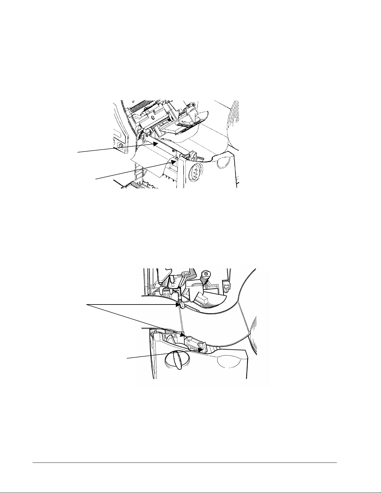
7. Lay the label strip across the supply guide (B). It is not necessary at this point to put
BCD
E
F
the label strip in the guide. Lay the label strip across the platen roller (C) and thread the
end of the strip into the gap between the platen roller and the auxiliary feed (D).
8. Reach under the platen roller and pull the label strip back towards the turn bar (F).
Thread the label strip under the guide roller (E) and around the turn bar (F) as shown
below.
18 •• Loading Supplies Users Manual - 610/611/612 Printers
Page 23

9. Bring the label strip over the guide roller and across the platen roller to the left of the
strip that is already around the roller. Place the end of the strip into the auxiliary feed
and feed it through using the advance knob (G). Press the advance knob toward the
printer to engage the advance shaft. Turn the knob counter-clockwise to feed the label
strip. Continue feeding the label strip until it appears coming out of the cutter.
G
10. Insert the label strip into both sides of the supply guide. Adjust the supply guide by
moving the right guide in or out, depending on the stock width. The label strip should be
in the guide slots on the inner edges of the strip and under the sensor at the back right
of the guide. Adjust the supply guide so that it just matches the width of the inner strip.
The outer strip will be slightly loose.
11. Push the black deflector tab down. Release the printhead latch, but do not lock the
printhead assembly down. Gently roll the supply roll back to tighten the label strip.
Continue until the label strip is snug around the turn bar. Lock the printhead down.
Note: If the printer is not used for an extended period, the label stock may take a “set”
where it goes around the turnbar. After a period of not printing, it is
recommended that you feed the material through the printer until the “set”
material has gone through the knife. This will reduce the possibility of jamming.
Users Manual - 610/611/612 Printers Loading Supplies •• 19
Page 24

Loading Ribbon
To load ribbon:
1. Open the cover.
2. Unlock the printhead by turning the retaining latch.
3. Lift printhead assembly using the printhead tab until the assembly locks into place.
CAUTION
Make sure you use only approved Paxar supplies. See
Appendix A, "Specifications and Accessories" for a list of
Paxar supplies or contact your Paxar Representative for
more information.
20 •• Loading Supplies Users Manual - 610/611/612 Printers
Page 25

4. Push the deflector tab down.
5. Slide the extra ribbon core on the take-up reel as far as it will go with the writing on
the end of the core facing out. Use your empty ribbon core as the take-up core. The
take-up core only fits on the take-up reel one way. (An extra take-up core is
available. See "Accessories" in Appendix A for more information.)
6. Remove the new ribbon from the package as shown. Do not wrinkle or crush the
new ribbon.
CAUTION
Since some supplies are more abrasive to printheads than
others, using a ribbon wider than your supply helps protect
the printhead. Failure to do this may void your printhead
warranty.
Users Manual - 610/611/612 Printers Loading Supplies •• 21
Page 26

7. Slide the ribbon onto the back reel as far as it will go with the writing on the end of
the core facing out. The ribbon roll only fits on the reel one way. Carefully unwind a
few inches of ribbon from the bottom of the roll.
Take-up Reel
Back Reel
8. Carefully feed the ribbon under both ribbon rollers and printhead as shown.
9. Tape the ribbon to the take-up core. Do not tape the ribbon to the take-up reel.
22 •• Loading Supplies Users Manual - 610/611/612 Printers
Page 27

10. Align the ribbon with the printhead and supply.
CAUTION
Make sure the ribbon is straight and centered throughout
the path.
11. Rotate the take-up core until the leader is past the printhead.
12. Remove any slack in the ribbon by turning the take-up reel clockwise.
13. Hold the printhead assembly by the printhead tab while pressing down on the
printhead release.
Users Manual - 610/611/612 Printers Loading Supplies •• 23
Page 28

14. Close the printhead by pressing down on the thumb well until you hear it click into
place. Close the cover.
Adjusting the Wide/Narrow Knobs
You may need to adjust the two wide/narrow knobs according to the width of your
supply. For supply that is more than two inches, adjust the knobs to the wide setting.
For supply that is two inches or less, adjust the knobs to the narrow setting.
You must adjust both of the knobs to
the same position.
If you experience ribbon smudging in cold, dry environments, adjust the wide/narrow
knobs to the wide setting.
For wide supplies, push down and turn the wide/narrow knobs clockwise with a
screwdriver.
24 •• Loading Supplies Users Manual - 610/611/612 Printers
Page 29

For narrow supplies, turn the wide/narrow knobs counter-clockwise with a screwdriver
until it pops back up.
The adjustment is shown in the wide position.
Users Manual - 610/611/612 Printers Loading Supplies •• 25
Page 30

Printing
♦ This chapter explains how to -
♦ Use on-demand mode printing.
♦ Print an error label.
♦ Adjust the print positions.
♦ Print care symbols and special characters, such as the Euro-Dollar symbol.
Printing
The host sends online packets containing print jobs to the printer.
To print:
1. Turn on the printer.
2. Download a format and a batch. See your System Administrator for more
information about downloading packets.
3. The printer prints a strip of labels.
4. Remove the printed labels.
26 •• Printing Users Manual - 610/611/612 Printers
Page 31

Printer Alignment - Top and Bottom Copy – 612
The 612 printer must be adjusted so that the copy on the top and bottom of the label
lines up correctly. On the base of the unit near the supply roll is an adjustment guide
(see the picture on page 17). On the guide are several black bars, each of which
corresponds to a set of label lengths. The guide allows an approximate adjustment
when the label material is loaded (see Loading Labels – 612 on page 15). After the
supplies are loaded, the printer must be adjusted to properly align the print on the top
and bottom of the finished label.
1. Unlatch the printhead. Turn the Label Length Adjustment Knob until the pointer on
the turn bar falls within the black bar corresponding to the length of the label to be
printed.
2. With the printhead resting in the down position, but not latched, gently turn the
supply roll back until the stock is snug around the turn bar. Latch the printhead.
3. Load a batch and print several test labels, until labels are printed with print on both
the top and bottom. Note the alignment of the front and back copy. If the back copy
is too far toward the top of the label, turn the Label Length Adjustment Knob counterclockwise. If the back copy is too far toward the bottom of the label, turn the Label
Length Adjustment Knob clockwise.
4. Run several more labels and check the alignment. Make further adjustments as
necessary.
Printing an Error Label
If the printer displays a data error (errors 0 -
499), press Feed to print an error label and
continue printing. See your System
Administrator about the error label.
NOTE: Do not print an error label on the
612 printer.
Users Manual - 610/611/612 Printers Printing •• 27
Page 32

Non-Printing Zone
A non-print zone is required for text (light copy) and bar codes (heavy copy). Thin lines
and most fonts require a 0.25-inch non-print zone at the leading edge of the label. Bar
codes, bold fonts, and Care symbol fonts require a 0.375-inch non-print zone at the
leading edge of the label. Without these non-print zones, the ribbon sticks to the supply
and can cause jams.
0.375 inch non-print zone
Feed
PCMate Software has a built-in non-print zone; however, some third party software
packages may not. You should verify the non-print zone or check defaults.
Regardless of the software package you are using to
create/design formats, do not place logos or bar codes too
close to the edge of your supply.
Preventing Jams
To prevent jams
♦ Design formats using the appropriate non-print zones.
♦ Do not leave the printhead closed (in the locked position) longer than 30 minutes
without printing. Open (unlock) the printhead before a break period, at the end of
each shift, and at the end of each day.
28 •• Printing Users Manual - 610/611/612 Printers
Page 33

Printing Serial Bar Codes
Currently, the 610 / 611 / 612 printer does not support printing serial (ladder) bar codes.
Parallel (Picket Fence) Bar Code Serial (Ladder) Bar Code
Adjusting Print Positions
You can adjust the supply, print, and margin positions by using the control panel
buttons. Make sure a batch is not waiting to print, the printer is not paused, or has an
error before you change the settings.
To change the supply, print, or margin positions:
1. Press Pause.
2. Press Feed and Clear (at the same time) once to select the supply position, twice to
select the print position, and three times to select the margin position. These
buttons act as toggle switches between the three (supply, print, and margin) position
adjustments.
When you select the position to change, the current setting
is displayed.
3. Press Feed to decrease the current position by one dot or press Feed for two
seconds to decrease the value by 10 dots.
OR
Press Clear to increase the current position by one dot or press Clear for two
seconds to increase the value by 10 dots.
If the position has a negative value, the supplies light is on.
After you adjust the position (and release the buttons), the
setting is displayed.
4. Press Pause when you are done making adjustments.
Users Manual - 610/611/612 Printers Printing •• 29
Page 34

Resend the format so these changes take effect. Change the settings after the batch is
1.
2.
done printing.
Review the following definitions for the different print position adjustments.
Supply Position Adjusts the machine to print at the vertical 0,0 point on
the supply. Increase the supply position to move print
up, decrease to move print down on the label. The
range is -300 to +300 dots.
The supply position adjustment should only be made on
initial printer setup. For format adjustments, change the
print position.
Print Position Adjusts where data prints vertically on the supply.
Increase the print position to move print up, decrease
to move print down. The range is -99 to 99 dots.
Margin Position Adjusts where data prints horizontally on the supply.
Increase the margin position to move print to the right,
decrease to move print to the left. The range is -99 to
99 dots.
Adjusting the Cut Angle
To adjust the cut angle:
Loosen the thumbscrews.
Slightly rotate the knife to the left or to the right. The knife may appear to sit at a
slight angle to the printer.
3.
Tighten the thumbscrews.
Cut another batch of tags. If you are unable to adjust for a straight cut, call Technical
Support.
30 •• Printing Users Manual - 610/611/612 Printers
Page 35

Using the Knife
The installed knife is two and a half (2-1/2) inches away from
the printhead. Pressing and holding Feed for two seconds
marks the tag under the printhead to be cut when it reaches the
knife. Depending on the length of your supply, you may lose up
to two tags after the last batch.
The knife operates when the printer is running. If the Printer is
paused, the knife stops cutting.
Adjusting the Drop Tray
Depending on the model purchased, your printer may have a
drop tray stacker. Adjust the drop tray by removing the plastic
pins and re-inserting them according to the diagram below.
Select the setting based on the length of your label.
________
Users Manual - 610/611/612 Printers Printing •• 31
Page 36

Care Symbol Font Samples
Ginetex Font
The following table shows the characters available with Ginetex Font 70 and Font 71.
Font 70 can fit five (5) symbols in 22mm (0.88 inches).
Nafta Font
The following table shows the characters available with Nafta Font 72 and Font 73.
32 •• Printing Users Manual - 610/611/612 Printers
Page 37

Care and Maintenance
This chapter tells you how to
♦ Clear supply jams
♦ Clear knife jams
♦ Clean the printhead and platen roller
♦ Replace a printhead
♦ Adjust print contrast
♦ Replace a fuse
♦ Lubricate the knife
CAUTION
Do not use sharp objects to clean the printhead. This may
damage the printer and void your warranty.
Users Manual - 610/611/612 Printers Care and Maintenance •• 33
Page 38

Clearing Supply Jams
When you are printing and a jam occurs, the Supplies light on the printer's front panel
blinks. To clear the jam:
1. Turn off the printer.
2. Open the cover and printhead assembly.
3. If necessary, remove the supply roll and ribbon.
4. Remove the jammed supply and reload the supply roll.
5. Close the printhead assembly and turn on the printer.
6. Press Feed to position the supply under the printhead.
Clearing a Knife Jam
If tags are jammed in the knife, the printer displays 760 on the LED. To clear a knife
jam, you might have to disconnect the stacker from the knife.
1. Turn the printer off.
2. You can see the tag path in the knife by looking through the slot on the top of the
knife. Clear the tag path by using a tool, such as a screwdriver or needle-nose
pliers, to pull the jammed tags out of the knife.
CAUTION
DO NOT PLACE YOUR FINGERS NEAR THE KNIFE’S BLADE. DO NOT USE
EXCESSIVE FORCE TO REMOVE TAGS BECAUSE
DAMAGE TO THE KNIFE MAY OCCUR.
3. Turn on the printer. Send a test batch of tags to the printer.
34 •• Care and Maintenance Users Manual - 610/611/612 Printers
Page 39

Cleaning
The rate and frequency at which you print determines how often you must clean the
printer.
You may need to clean the printhead and platen roller:
♦ If there is any lint or debris build up in
the supply path
♦ Whenever you load new supplies
♦ Daily if your printer is in an
excessively dirty, hot, or humid
environment
♦ When you see voids in the print as
shown.
You may have to clean the supply sensor more often if you frequently receive supply
error codes.
Paxar recommends that you clean the printhead and platen roller at least once a day
when the printer is in use. You may need to clean more frequently depending on
usage.
To clean the printhead, supply sensor, and platen roller:
1. Turn off the printer.
2. Open the cover and printhead assembly.
3. Remove the label roll and ribbon (when cleaning the printhead).
4. Clean the platen roller with a dry cloth or small brush. However, if there is adhesive
gum build-up on the platen roller, moisten a cotton swab with isopropyl alcohol.
Turn the platen roller with your finger and run the cotton swab or dry cloth across it.
Make sure the platen roller is clean all the way around.
Users Manual - 610/611/612 Printers Care and Maintenance •• 35
Page 40

5. Moisten another cotton swab with isopropyl alcohol. Rub the cotton swab across the
printhead and remove any build-up.
6. Rub the cotton swab across the supply sensor and remove any build-up.
7. Clean the build-up in the supply path.
8. Let the printer dry and reload your supplies.
36 •• Care and Maintenance Users Manual - 610/611/612 Printers
Page 41

9. Close the exit cover by pushing firmly on it as shown. Both latches will click into
place.
10. Close the cover and printhead assembly.
11. Turn on the printer.
12. Press Feed to position the supply under the printhead.
Replacing the Printhead
You may have to replace the printhead if it is damaged or worn-out. For example, you
may see 616 (bad dot or dots) or 768 (printhead failure) error codes.
CAUTION
The printhead is sensitive to static electricity, which can damage the
printhead or reduce its life. Ground yourself by touching some metal, such
as the printer's metal base, before touching the printhead. Clean the
printhead to remove any salt or oil left from handling prior to operation.
To replace the printhead:
1. Turn off the printer.
2. Open the cover.
Users Manual - 610/611/612 Printers Care and Maintenance •• 37
Page 42

3. Unlock the printhead by turning the retaining latch.
4. Press forward and down on the two latches on top of the printhead assembly as
shown. The printhead will drop down.
5. Lift the printhead assembly using the printhead tab and push back until the
printhead assembly clicks into place.
38 •• Care and Maintenance Users Manual - 610/611/612 Printers
Page 43

6. Carefully unplug the cable from the printhead as shown.
CAUTION
The printhead is sensitive to static electricity, which can
damage the printhead or reduce its life. Ground yourself by
touching some metal, such as the printer's metal base,
before touching the printhead.
7. Carefully plug the cable into the new printhead. The cable connector is keyed,
so you cannot incorrectly connect the cable. However, it is normal to feel some
resistance when correctly connecting the cable.
8. Align the new printhead with the tabs.
Users Manual - 610/611/612 Printers Care and Maintenance •• 39
Page 44

9. Snap the printhead into place.
Do not touch here
Make sure the printhead cable does not
touch the ribbon roll.
10. Clean the new printhead with a cotton swab dipped in isopropyl alcohol to remove
any salt or oil left from handling.
11. Let the printhead dry and reload your supplies.
12. Close the printhead assembly and the cover.
13. Turn on the printer.
14. Press Feed to position the supply under the printhead.
40 •• Care and Maintenance Users Manual - 610/611/612 Printers
Page 45

Adjusting the Print Contrast
You may need to adjust the print contrast if the printing is too light or too dark. Having the
correct print contrast is important because it affects how well your bar codes scan and how
long your printhead lasts.
Using a thin screwdriver, turn contrast knob clockwise for darker print; turn counterclockwise for lighter print.
__________
You only have to turn the contrast
adjuster slightly.
__________
Users Manual - 610/611/612 Printers Care and Maintenance •• 41
Page 46

Replacing the Fuse
The printer is shipped with a 115-volt or 220 volt slo-blow fuse.
To replace the fuse:
1. Disconnect the printer from the power source.
2. Use a screwdriver to pry open the fuse box in the back of the printer as shown.
Fuse Box
Fuse
3. Remove the old fuse and insert a new one.
4. Slide the fuse box back into the printer.
42 •• Care and Maintenance Users Manual - 610/611/612 Printers
Page 47

Lubricating the Knife
We recommend lubricating the knife after using 15 rolls of supply or performing 100,000
cuts.
To prevent excessive wear on the knife, regularly lubricate the knife cams. The cam are
located directly below the guiding holes.
To lubricate the knife:
1. Turn off the printer.
2. Lightly coat a long cotton swab with
multi-purpose grease.
3. Insert the cotton swab into one of the two
guiding holes until it stops on the cam.
4. Move the cotton swab up and down
several times to coat the cam with
grease.
5. Repeat steps 2 – 4 for the other cam.
6. Wipe off any excess grease from the top
cover of the knife.
7. Turn on the printer.
Users Manual - 610/611/612 Printers Care and Maintenance •• 43
Page 48

Troubleshooting
This chapter provides;
♦ Information about printing a test label.
♦ Solutions to minor printing problems.
♦ Explanations of error messages you may receive while using the printer.
44 •• Troubleshooting Users Manual - 610/611/612 Printers
Page 49

Printing a Test Label
To print test labels:
NOTE: Do not print a test label on the 612 printer.
Press Feed and Pause simultaneously. Hold for one second and release. Labels
similar to these print:
The first label shows the printer’s configuration by packer (A – G). The second label shows the
model number, software version, stock count, voltage, print contrast, printhead resistance, number of
bad dots, installed options, and DIP switch settings.
If test labels do not print, press Feed and try again. If that does not solve the problem, call Technical
Support.
Users Manual - 610/611/612 Printers Troubleshooting •• 45
Page 50

Troubleshooting
This section helps you correct some problems that may occur.
Problem Action
Error message appears during
startup.
Does not print. Check supply.
Does not feed. Set wide/narrow knobs correctly. Try the narrow setting first,
Partially printed data. Clean the printhead.
Printing shadows or smears Clean the printhead.
Light printing. Change supply.
Heavy printing. Clean the printhead.
Voids in printing. Clean the printhead.
Blank labels print or 750 series
errors.
Turn off the printer, wait fifteen seconds and then turn on the
printer. Call Technical Support if the error message
reappears.
Check ribbon.
Send a corrected batch.
if the printing is too light, use the wide setting.
Send a corrected batch.
Change supply.
Check ribbon.
Adjust the print contrast.
Check wide/narrow knobs. Try the narrow setting first, if the
printing is too light, use the wide setting.
Check ribbon.
Change supply.
Adjust the print contrast.
Check the wide/narrow knobs. Try the narrow setting first, if
the printing is too light, use the wide setting.
Check ribbon
Change the supply type.
Check ribbon.
Leave printhead unlatched when not in use.
Clean supply sensors.
If you cannot fix a problem, call Technical Support.
46 •• Troubleshooting Users Manual - 610/611/612 Printers
Page 51

Error Messages
You may receive the following types of error messages:
♦ Data Errors
♦ Communication Errors
Some errors numbered 400 – 438 and 500 – 574 are internal software errors. Errors
numbered 900 – 999 are hard printer failures. If you cannot clear an error, turn off the
printer, wait several seconds and then turn on the printer. Call Technical Support if you
receive any error message not listed in this chapter.
Data Errors
Errors 001 to 405 and 429 to 435 are data errors. This type of error indicates that incorrect data was
sent to the printer, and the printer is ignoring it. Your System Administrator should correct the
packet and send it back to the printer.
Error Description / Action
001 Packet ID number must be 1 to 999.
002 Name must be 1 to 8 characters inside quotes or a printer-assigned name (“ ”).
003 Action must be A (add) or C (clear).
004 Supply length is invalid.
005 Supply width is invalid.
006 Storage devise must be R (volatile RAM).
007 Unit of measure must be E (English), M (Metric), or G (Dots).
010 Field ID number is outside the range 0 to 999.
011 Field length exceeds 2710.
012 Row field position is greater than the maximum stock dimension.
013 Column field position is greater than the maximum stock dimension.
014 Font selector is invalid.
015 Character rotation must be 0 (0 degree), 1 (90 degree), 2 (180 degree), or 3 (270 degree).
016 Field rotation must be 0 (0 degree), 1 (90 degree), 2 (180 degree), or 3 (270 degree).
017 Field restriction must be V (variable) or F (fixed).
Users Manual - 610/611/612 Printers Troubleshooting •• 47
Page 52

018 Code page selection defined in the field must be 0 (Internal), 1 (ANSI), 2 (DOS
437), or 3 (DOS 850).
020 Vertical magnification must be 1 to 7.
021 Horizontal magnification must be 1 to 7.
022 Color must be B, D, O, R, or W.
023 Intercharacter gap must be 0 to 99 dots.
024 Field justification must be B (balanced), C (centered), E (end), L (left), or R (right).
025 Data length is outside the range 0 to 2710.
030 Bar code height must be at least 20 (English), 51 (Metric), 40 (Dots), or is not within the
supply dimensions.
031 Human readable option must be 0, 1, 5, 6, 7, or 8.
032 Bar code type is invalid.
033 Bar code density is invalid.
040 Line thickness must be 0 to 99 dots.
041 Line direction must be 0, 90, 180, or 270.
042 The line segment or box end row is defined outside of printable area.
043 The line segment or box end column is defined outside of printable area.
044 Dot pattern for line or box must be “ “.
045 Line length is defined beyond the maximum length.
046 Line type must be S (segment) or V (vector).
051 Imaging mode in the graphic header must be 0.
101 Format referenced by batch is not in memory.
102 Print quantity is outside the range 0 to 32000.
104 Batch mode must be N (new) or U (update).
105 Batch separator must be 0 (off) or 1 (on).
106 Print multiple is outside the range 1 to 999.
107 Cut multiple is outside the range 0 to 999.
108 Multiple part supply is outside the range 1 to 5.
109 Cut type is invalid.
200 Option number must be 1, 4, 30, 31, 42, 50, 60, or 61.
201 Copy length is outside the range 0 to 2710.
202 Copy start position must be 1 to 2710.
203 Destination start position must be 1 to 2710.
48 •• Troubleshooting Users Manual - 610/611/612 Printers
Page 53

204 Source field must be 0 to 999.
205 Copy type must be 1 (Copy after rules) or 2 (Copy before rules).
206 Increment / Decrement selection must be I (increment) or D (decrement).
207 Incrementing start position must be 0 to 2710.
208 Incrementing end position must be 0 to 2710.
209 The incrementing amount must be 0 to 999.
210 Security value for a PDF417 bar code must be 0 to 8.
211 Narrow element value is less than 1 or greater than 99.
212 Wide element value is less than 1 or greater than 99.
213 Dimension must be 1 to 30 for a column or 3 to 90 for a row.
214 Truncation code must be S (standard) or T (truncated bar code).
215 Aspect code must be C (columns) or R (rows).
216 Option definition must be S (set) or T (template).
217 Input device must be D (default), H (host), K (keyboard), N (none), or S (scanner).
218 Pad direction must be L (from left) or R (from right).
219 Pad character is outside the range 0 to 255.
220 Check digit selection must be G to generate check digit.
221 Primary or secondary price format is outside the range 1 to 15.
222 Data type restriction is outside the range of 1 to 6.
223 Option is not valid for the field.
224 Bar code Intercharacter gap must be 0 to 99 in printer dots.
251 Power up mode must in 0 (online) or 1 (offline).
252 Language selection must be 0 (English).
253 Batch separator code must be 0 (off) or 1 (on).
254 Slash zero selection must be 0 (standard zero) or 1 (slash zero).
255 Supply type must be 0 (black mark), 1 (die cut), or 2 (continuous).
256 Ribbon selection must be 0 (direct) or 1 (transfer).
257 Feed mode must be 0 (continuous) or 1 (On-Demand).
258 Supply position is outside the range.
259 Contrast adjustment must be –390 to 1000 dots.
260 Print adjustment must be –99 to 99 dots.
261 Margin adjustment must be –99 to 99 dots.
262 Speed adjustment is invalid.
Users Manual - 610/611/612 Printers Troubleshooting •• 49
Page 54

263 Primary monetary symbol is invalid.
264 Secondary symbol selection must be 0 (none) or 1 (primary secondary sign).
265 Monetary decimal places must be 0 to 3.
266 Character string length in Packet E must be 5 (MPCL control characters) or 7
(ENQ/IMD command character).
267 Baud rate selection must be 0 (1200), 1 (2400), 2 (4800), 3 (9600), 4 (19.2), or 5 (38.4).
268 Word length selection must be 0 (7 bits) or 1 (8 bits).
269 Stop bits selection must be 0 (1 bit) or 1 (2 bits).
270 Parity selection must be 0 (none), 1 (odd), or 2 (even).
271 Flow control selection must be 0 (none), 1 (DTR/DSR), 2 (CTS/RTS), or 3
(XON/XOFF).
272 Internal code page selection must be 0 (internal), 1 (ANSI), 2 (DOS 437), or 3 (DOS
850).
273 Cut adjustment must be –300 to +300 dots.
282 RS232 Trailer string is too long. Use a maximum of 3 characters.
283 ENQ Trailer string is too long. Use a maximum of 3 characters.
284 The buffer type must be T (transmit), R (receive), I (image), F (format, batch date and
graphics), D (downloadable fonts), or V (vector/scalable fonts).
285 The storage device type must be N (non-volatile RAM) or R (volatile RAM).
286 The buffer size is invalid.
287 The printhead width must be 0.
290 Action must be 0 (disable) or 1 (enable) for Backfeed Control.
291 Dispense position must be 50 to 200 dots and/or the backfeed distance is greater than the
dispense position.
292 Backfeed distance must be 10 to 200 dots.
310 Check digit scheme number must be 1 to 10.
311 Modulus must be 2 to 11.
314 Check digit algorithm must be D (sum of digits) or P (sum of products).
325 Duplicating direction must be 0 or 1.
327 Amount of row adjustment must be 0 to 999.
328 Duplicate count must be 0 to 999.
340 Bitmap line encoding must be H (hex) or R (run length).
350 Font selector must be 1 to 9999.
351 Font data length must be 68 to 16384.
50 •• Troubleshooting Users Manual - 610/611/612 Printers
Page 55

352 Insufficient font memory is available for the downloaded font.
380 Job request is outside the range 0 to 4.
400 Invalid character following {.
401 Internal software failure. Call Technical Support.
402 Field separator is not in the expected location.
403 Field separator was not found.
404 The number of string that is currently being processed is too long.
405 Too many fields exist in the format. You cannot have more than 1000 fields in the
format. Lines, boxes, and constant text fields count as fields.
Users Manual - 610/611/612 Printers Troubleshooting •• 51
Page 56

Communication Failures
Errors 409 to 413 usually indicate a communication failure. These errors happen when the host and
the printer cannot communicate. Ask your System Administrator for help.
Error Description/Action
409 Printer memory is full. Delete unnecessary formats or graphics from memory. Try run
length encoding for large graphics.
410 Parity mismatch.
411 Framing error (baud rate mismatch). This error may appear when you turn off the
printer.
412 Flow control mismatch.
413 Receive buffer is full. Check flow control settings.
414 The internal keyboard buffer is full or you need a new keypad.
427 Format name must be 1 to 8 characters inside quotes or a printer-assigned
name (“ “).
428 Batch name is invalid or graphic not found.
429 A field number appears more than once in a format.
430 The format uses a graphic file that cannot be found.
433 The batch references a field number that does not exist in the format.
497 An error occurred during the loop back test on the parallel port. Call Service.
499 An error occurred during the loop back test on the serial port. Call Service.
52 •• Troubleshooting Users Manual - 610/611/612 Printers
Page 57

Data Formatting Errors
Errors 571 to 618 are data formatting errors. This type of error happens when a field prints
incorrectly. Your System Administrator can correct the format, batch, or graphic packet and send
the print job again. For errors 571 to 614, the printer will still print, but the data may be incomplete,
missing, or wrong.
Error Description/Action
571 UPC or EAN bar code data length in the batch doesn’t fit the format.
572 Batch data doesn’t fit the format, the field contains blanks, or data mismatch.
573 Batch data in price field doesn’t fit the format or the field contains blanks.
574 Batch data in check digit scheme doesn’t fit the format, or the field contains blanks.
575 The graphic included in your format could not be found.
600 Imaging error because the batch was refused.
601 An error occurred while the batch was imaging.
602 The batch was not found during imaging.
611 Font, bar code, or density in the batch doesn’t fit the format.
612 Batch data is missing or doesn’t match the format.
613 Reference point off tag.
614 Portion of field off tag.
615 Bar code width is greater than 16 inches, or keywords of PDF417 bar code exceed 928.
616 A bad dot falls on a bar code that cannot be shifted. Call Service or replace the
printhead.
618 Magnification must be 1 to 7.
620 Font and printhead density mismatch. Check the font or verify the correct printhead
(203 dpi or 300 dpi) is installed.
Users Manual - 610/611/612 Printers Troubleshooting •• 53
Page 58

Machine Faults
Errors 700 to 765 happen when there is a problem with the printer.
Error Description/Action
700 An error is pending and the printer cannot continue with the batch.
701 Printer received a command that it cannot execute while it is running.
702 Check your printer’s SETUP settings.
703 The printer sensed a calibration of different-sized black marks.
704 Printer didn’t detect a sense mark within the maximum feed length or out of supplies.
Check or load supplies.
705 Invalid batch received.
750 Printhead is overheated. Turn off the printer and let it cool.
751 Printer didn’t detect a sense mark when expected.
752 Printer detected a sense mark in the wrong place.
753 Printer detected a sense mark that is too long.
754 Out of ribbon or ribbon jam. Check or load ribbon. Remove any slack in the ribbon by
turning the take-up reel clockwise. Load a new ribbon.
755 Printhead is open. Close the printhead.
756 Out of supplies. Load supplies.
757 Reload supplies (supply length mismatch).
758 The supply was not seen or the On-Demand sensor is not working correctly. Check for
a supply jam. Clear the supply path or reload supplies. This error may occur if you
remove a label too quickly in the On-Demand mode. The printer does not recalibrate
after this error.
759 Knife is not moving. Call Technical Support.
760 Knife jam. Call Technical Support.
761 Stacker is full or jammed. Empty the stacker before continuing.
762 Low battery. Recharge the battery.
763 Waiting to dispense label. Press Feed.
764 Verifier failure. Call Technical Support.
765 The printhead has less than four bad spots. The printer can shift bar code fields to
avoid bad dots. Press Clear to continue printing. Print a test label to confirm the
number of bad dots.
54 •• Troubleshooting Users Manual - 610/611/612 Printers
Page 59

768 Printhead has more than 10 bad dots or is not connected. Make sure the printhead is
connected and if necessary, replace the printhead.
770 The print motor is not ready. Call Technical Support.
771 The format specified by the application was not found. Reload your application and
format and try again. If the problem continues, call Technical Support.
790 The printer is busy. Wait until the printer is idle (not receiving data or no batch waiting
to print) before you send any packets. This error may occur when you try to print a test
label if the printer is busy.
791 The printer has an error pending. Turn off the printer. Wait 15 seconds and turn it
back on. Resend the packets. If the problem continues, call Technical Support.
792 The printer is not initialized. Call Technical Support.
793 The printer job queue is full. Turn off the printer. Wait 15 seconds and turn it back on.
Resend the packets. If the problem continues, call Technical Support.
Errors numbered 900 – 999 are hard printer failures. Call Service if you receive these
messages.
________
Error 911 may appear when you turn off the printer.
________
Users Manual - 610/611/612 Printers Troubleshooting •• 55
Page 60

Appendix A - Specifications &
Accessories
Printer Specifications
Height: 12.5 inches (318 mm)
Width: 12 inches (305 mm)
Depth: 13 inches (330 mm)
Weight: 29 lb. (13 kg)
Shipping Weight: 33 lb. (15 kg)
Power: 115 Vac, 60Hz, 100 Vac, 50/60 Hz, 230 Vac, 50Hz
Operating Limits: For Thermal Transfer (ribbon) 40° to 95° F (4° to 35° C)
Printhead: Thermal at 4 inches (102 mm) wide 300 dpi (11.8 dots per mm)
Printing Method: Thermal Transfer (ribbon)
Print Speed: 4.0 inches (102 mm) per second
56 •• Appendix A - Specifications & Accessories Users Manual - 610/611/612 Printers
Page 61

Supply Specifications
Supply Types:
Fabric Label Kits:
Paxar Systems:
Paxar Europe:
Sizes:
Thermal Transfer Perforated Fabric Labels
Kits include fabric and ribbon
The fabric is available in standard widths, ranging from 1.0 inch
(25 mm) to 1.75 inches (45 mm), perforated to standard lengths.
The fabric is available in 25 mm to 50 mm widths.
Supplies are available in widths ranging from 1.0 inch (25 mm) to
4.25 inches (108 mm) and lengths ranging from 1.0 inches (25 mm)
to 12.5 inches (318 mm)
________
Contact your Paxar Representative for more
Information about kits and approved supplies.
Additional configurations may be available.
If you experience label jamming with narrow
Supplies in humid environments, store
Supplies separately from the printer in a dry,
Less humid environment.
________
Users Manual - 610/611/612 Printers Appendix A - Specifications & Accessories •• 57
Page 62

Ribbon Specifications
Ribbon Storage:
Ribbon Type:
Ribbon Widths:
Ribbon Length:
Do not leave ribbon in direct sunlight, high temperatures, or high
humidity.
CT1111 (Paxar Systems)
CT1111 is available in the following widths:
1.3 inches (33 mm)
1.61 inches (41 mm)
2.16 inches (55 mm)
4.1 inches (105 mm)
________
For best results, use a ribbon that is 0.25
Inches (6.35 mm) wider than your fabric.
________
23,600 inches (600 meters)
________
Contact your Paxar Representative for more
Information about approved ink products.
Additional configurations may be available.
________
58 •• Appendix A - Specifications & Accessories Users Manual - 610/611/612 Printers
Page 63

Accessories
♦ International Fonts
♦ Internal TwinAx/CoAx Protocol Convertor
♦ LAN Print Server RJ-45 Connector (10BaseT)
BNC Connector (10Base2)
♦ Printhead Assembly Kit
♦ Ribbon Take-up Core (available in two, three, or four inches)
♦ RTS/CTS Communication Cable – 119806
To order supplies or call customer support, use the numbers as follows;
Contacting Paxar
When ordering supplies in the U.S.A.
1-800-96PAXAR or (570) 888-6641
Fax: (570) 888-5230
When ordering spare parts in the U.S.A.
1-800-96PAXAR or (570) 888-6641
Fax: (570) 888-7416
For Machine Service or Technical Support in the U.S.A.
(570) 888-9116
Fax: (570) 888-7416
For International assistance, call your Paxar Representative
www.paxar.com
Users Manual - 610/611/612 Printers Contacting Paxar •• 59
 Loading...