


 Loading...
RocketLink™ Model 3202
2Base-TL Ethernet First Mile
G.SHDSL Modem
Getting Started Guide
Sales Office: +1 (301) 975-1000
Technical Support: +1 (301) 975-1007
E-mail: support@patton.com
WWW: www.patton.com
Part Number: 07M3202-GS, Rev. C
Revised: January 24, 2011
Patton Electronics Company, Inc.
7622 Rickenbacker Drive
Gaithersburg, MD 20879 USA
Tel: +1 (301) 975-1000
Fax: +1 (301) 869-9293
Support: +1 (301) 975-1007 Web: www.patton.com E-mail: support@patton.com
Trademark Statement
The term RocketLink is a trademark of Patton Electronics Company. All other trademarks presented in this document are the property of their respective owners.
Copyright © 2011, Patton Electronics Company. All rights reserved.
The information in this document is subject to change without notice. Patton Electronics assumes no liability for errors that may appear in this document.
Warranty Information
Patton Electronics warrants all Model 3202 components to be free from defects, and will—at our option—repair or replace the product should it fail within one year from the first date of shipment.
This warranty is limited to defects in workmanship or materials, and does not cover customer damage, abuse or unauthorized modification. If the product fails to perform as warranted, your sole recourse shall be repair or replacement as described above. Under no condition shall Patton Electronics be liable for any damages incurred by the use of this product. These damages include, but are not limited to, the following: lost profits, lost savings and incidental or consequential damages arising from the use of or inability to use this product. Patton Electronics specifically disclaims all other warranties, expressed or implied, and the installation or use of this product shall be deemed an acceptance of these terms by the user.

Summary Table of Contents |
|
|
1 |
General information ...................................................................................................................................... |
17 |
2 |
Applications overview.................................................................................................................................... |
22 |
3 |
Hardware installation.................................................................................................................................... |
26 |
4 |
Web configuration ........................................................................................................................................ |
32 |
5 |
Console and Telnet configuration ................................................................................................................. |
66 |
6 |
Contacting Patton for assistance ................................................................................................................... |
97 |
A |
Compliance information ............................................................................................................................ |
100 |
B |
Specifications .............................................................................................................................................. |
102 |
C |
Port pin-outs .............................................................................................................................................. |
105 |
3

Table of Contents |
|
|
|
Summary Table of Contents ........................................................................................................................... |
3 |
|
Table of Contents ........................................................................................................................................... |
4 |
|
List of Figures ................................................................................................................................................. |
9 |
|
List of Tables ................................................................................................................................................ |
11 |
|
About this guide ........................................................................................................................................... |
12 |
|
Audience............................................................................................................................................................... |
12 |
|
Structure............................................................................................................................................................... |
12 |
|
Precautions ........................................................................................................................................................... |
13 |
|
Safety when working with electricity ............................................................................................................... |
14 |
|
Preventing Electrostatic Discharge Damage .................................................................................................... |
14 |
|
General observations ....................................................................................................................................... |
15 |
|
Typographical conventions used in this document................................................................................................ |
16 |
|
General conventions ....................................................................................................................................... |
16 |
1 |
General information ...................................................................................................................................... |
17 |
|
Model 3202 overview ............................................................................................................................................ |
18 |
|
Model 3202 front panel......................................................................................................................................... |
19 |
|
LED descriptions ............................................................................................................................................ |
19 |
|
Model 3202 rear panel .......................................................................................................................................... |
20 |
|
Port descriptions ............................................................................................................................................. |
20 |
|
Reset button ................................................................................................................................................... |
21 |
|
Ground terminal ............................................................................................................................................. |
21 |
2 |
Applications overview.................................................................................................................................... |
22 |
|
Introduction .......................................................................................................................................................... |
23 |
|
Typical application ................................................................................................................................................ |
23 |
|
Distance charts ...................................................................................................................................................... |
24 |
|
Distance Chart 3200 Series (Per Wire Pair) .................................................................................................... |
24 |
|
Distance Chart Model 3202/4W (4 Wire/2 Pair) ............................................................................................ |
24 |
|
Distance Chart Model 3202/8W (8 Wire/4 Pair) ............................................................................................ |
25 |
3 |
Hardware installation.................................................................................................................................... |
26 |
|
Introduction .......................................................................................................................................................... |
27 |
|
Planning the installation........................................................................................................................................ |
27 |
|
Network diagram ............................................................................................................................................ |
28 |
|
IP related information ..................................................................................................................................... |
28 |
|
AC Power Mains ............................................................................................................................................. |
28 |
|
Location and mounting requirements ............................................................................................................. |
29 |
|
Installing the Model 3202 ..................................................................................................................................... |
29 |
|
Unpacking the Model 3202 ............................................................................................................................ |
29 |
|
Connecting cables ........................................................................................................................................... |
29 |
|
Grounding the Model 3202 and connecting power ......................................................................................... |
30 |
4

Model 3202 Getting Started Guide |
Table of Contents |
|
|
Configuring the Model 3202................................................................................................................................. |
31 |
Web configuration requirements ..................................................................................................................... |
31 |
Console configuration requirements ............................................................................................................... |
31 |
Telnet configuration requirements .................................................................................................................. |
31 |
4 Web configuration ........................................................................................................................................ |
32 |
Introduction .......................................................................................................................................................... |
34 |
Setting Up the WMI ............................................................................................................................................. |
34 |
TCP/IP setup .................................................................................................................................................. |
34 |
System Login .................................................................................................................................................. |
34 |
Basic Configuration Options ................................................................................................................................. |
35 |
Operation mode and MGMT port ................................................................................................................. |
35 |
DHCP server .................................................................................................................................................. |
36 |
LAN ............................................................................................................................................................... |
37 |
Review and save basic setup changes ............................................................................................................... |
38 |
Advanced Configuration Options.......................................................................................................................... |
39 |
LINE .............................................................................................................................................................. |
39 |
Line Type .................................................................................................................................................. |
39 |
Annex Type ............................................................................................................................................... |
39 |
TCPAM Type ........................................................................................................................................... |
40 |
Main Rate ................................................................................................................................................. |
40 |
SNR Margin ............................................................................................................................................. |
40 |
Line Probe ................................................................................................................................................. |
40 |
VLAN ............................................................................................................................................................. |
41 |
802.1Q Tag-Based VLAN ......................................................................................................................... |
43 |
Tag-Based VLAN Overview ................................................................................................................ |
43 |
Configuring 802.1Q VLAN Tagging .................................................................................................. |
44 |
Port-Based VLAN ..................................................................................................................................... |
46 |
Port-Based QinQ ...................................................................................................................................... |
47 |
Q-in-Q Tagging ................................................................................................................................. |
48 |
Q-in-Q Tag Removal ......................................................................................................................... |
49 |
Quality of Service (QoS) ................................................................................................................................. |
49 |
Port Based Priority .................................................................................................................................... |
50 |
VLAN Tag Priority ................................................................................................................................... |
51 |
WRR Scheduling Configuration Example .......................................................................................... |
52 |
IP DSCP Priority ...................................................................................................................................... |
53 |
Differentiated Services Overview ........................................................................................................ |
53 |
Configuring DSCP Options ............................................................................................................... |
55 |
Rate Control ................................................................................................................................................... |
56 |
Status Options....................................................................................................................................................... |
57 |
LINE Status .................................................................................................................................................... |
57 |
MGMT Status ................................................................................................................................................ |
57 |
LAN Status ..................................................................................................................................................... |
58 |
Administration Options ........................................................................................................................................ |
58 |
5

Model 3202 Getting Started Guide |
Table of Contents |
|
|
Security Administration .................................................................................................................................. |
58 |
User Profiles .............................................................................................................................................. |
59 |
Remote Management Hosts ...................................................................................................................... |
59 |
SNMP Administration .................................................................................................................................... |
60 |
Community Pool ...................................................................................................................................... |
61 |
Trap Host Pool ......................................................................................................................................... |
62 |
Utility Options...................................................................................................................................................... |
62 |
System Information ........................................................................................................................................ |
62 |
Configuration Tool ......................................................................................................................................... |
63 |
Upgrade .......................................................................................................................................................... |
64 |
Logout ............................................................................................................................................................ |
64 |
Restart ............................................................................................................................................................ |
65 |
5 Console and Telnet configuration ................................................................................................................. |
66 |
Introduction .......................................................................................................................................................... |
68 |
Log in to the console interface ........................................................................................................................ |
68 |
Log in using Telnet ......................................................................................................................................... |
68 |
Interface commands ........................................................................................................................................ |
68 |
Window structure ........................................................................................................................................... |
69 |
Main Menu Tree ................................................................................................................................................... |
70 |
Menu tree for authorized users ........................................................................................................................ |
70 |
Menu tree for unauthorized users .................................................................................................................... |
71 |
Enable Command Menu ....................................................................................................................................... |
72 |
Setup Command Menu......................................................................................................................................... |
73 |
G.SHDSL ....................................................................................................................................................... |
73 |
Mode ........................................................................................................................................................ |
74 |
Link .......................................................................................................................................................... |
74 |
Annex Type ............................................................................................................................................... |
74 |
TCPAM Type ........................................................................................................................................... |
74 |
Maximum Main Rate ................................................................................................................................ |
74 |
SNR Margin ............................................................................................................................................. |
74 |
Line Probe ................................................................................................................................................. |
75 |
Clear ......................................................................................................................................................... |
75 |
LAN ............................................................................................................................................................... |
75 |
VLAN ............................................................................................................................................................. |
76 |
Mode ........................................................................................................................................................ |
76 |
802.1Q VLAN ................................................................................................................................... |
77 |
Port-Based VLAN ............................................................................................................................... |
78 |
QoS ................................................................................................................................................................ |
79 |
Mode ........................................................................................................................................................ |
79 |
Queue Weight ........................................................................................................................................... |
80 |
Queue Schedule ........................................................................................................................................ |
80 |
Port-Based Priority QoS ............................................................................................................................ |
81 |
VLAN Tag Priority QoS ........................................................................................................................... |
81 |
6

Model 3202 Getting Started Guide |
Table of Contents |
|
|
IP DSCP Priority QoS .............................................................................................................................. |
82 |
List ............................................................................................................................................................ |
83 |
Rate ................................................................................................................................................................ |
83 |
MGMT .......................................................................................................................................................... |
84 |
DHCP ............................................................................................................................................................ |
84 |
DHCP Server ............................................................................................................................................ |
85 |
DHCP Fixed Host .................................................................................................................................... |
85 |
DNS Proxy ..................................................................................................................................................... |
86 |
Host Name ..................................................................................................................................................... |
86 |
Factory Default ............................................................................................................................................... |
86 |
Status Command Menu ........................................................................................................................................ |
87 |
G.SHDSL Status ............................................................................................................................................ |
87 |
Interface Status ............................................................................................................................................... |
87 |
Show Command Menu ......................................................................................................................................... |
88 |
Write Command ................................................................................................................................................... |
88 |
Reboot Command................................................................................................................................................. |
89 |
Ping Command ..................................................................................................................................................... |
89 |
Administration Command Menu .......................................................................................................................... |
90 |
User Profile ..................................................................................................................................................... |
90 |
Modify/Add User ...................................................................................................................................... |
90 |
Security ........................................................................................................................................................... |
91 |
Telnet TCP Port ....................................................................................................................................... |
91 |
Legal IP Address Pool ................................................................................................................................ |
91 |
SNMP ............................................................................................................................................................ |
92 |
Community .............................................................................................................................................. |
92 |
Trap host .................................................................................................................................................. |
93 |
Supervisor Password and ID ........................................................................................................................... |
94 |
Supervisor Password .................................................................................................................................. |
94 |
Supervisor ID ............................................................................................................................................ |
94 |
Utility Command Menu ....................................................................................................................................... |
95 |
Upgrade main software ................................................................................................................................... |
95 |
Backup system configuration .......................................................................................................................... |
95 |
Restore system configuration ........................................................................................................................... |
95 |
Exit Command...................................................................................................................................................... |
96 |
6 Contacting Patton for assistance ................................................................................................................... |
97 |
Introduction .......................................................................................................................................................... |
98 |
Contact information.............................................................................................................................................. |
98 |
Warranty Service and Returned Merchandise Authorizations (RMAs)................................................................... |
98 |
Warranty coverage .......................................................................................................................................... |
98 |
Out-of-warranty service ............................................................................................................................. |
99 |
Returns for credit ...................................................................................................................................... |
99 |
Return for credit policy ............................................................................................................................. |
99 |
RMA numbers ................................................................................................................................................ |
99 |
7

Model 3202 Getting Started Guide |
Table of Contents |
|
|
|
Shipping instructions ................................................................................................................................ |
99 |
A |
Compliance information ............................................................................................................................ |
100 |
|
Compliance ......................................................................................................................................................... |
101 |
|
EMC compliance: ......................................................................................................................................... |
101 |
|
Radio and TV interference (FCC Part 15)........................................................................................................... |
101 |
|
CE Declaration of Conformity ............................................................................................................................ |
101 |
|
Authorized European Representative ................................................................................................................... |
101 |
B |
Specifications .............................................................................................................................................. |
102 |
|
G.SHDSL Connector.......................................................................................................................................... |
103 |
|
G.SHDSL Specifications ..................................................................................................................................... |
103 |
|
DSL Modulation ................................................................................................................................................. |
103 |
|
Ethernet Connector............................................................................................................................................. |
103 |
|
LAN Protocols..................................................................................................................................................... |
103 |
|
VLAN Support.................................................................................................................................................... |
103 |
|
QoS Support ....................................................................................................................................................... |
103 |
|
Management Connector...................................................................................................................................... |
103 |
|
Management Interface ......................................................................................................................................... |
104 |
|
Front Panel Indicators ......................................................................................................................................... |
104 |
|
Power Supply ...................................................................................................................................................... |
104 |
|
Environment ....................................................................................................................................................... |
104 |
|
Dimensions ......................................................................................................................................................... |
104 |
|
Weight ................................................................................................................................................................ |
104 |
C |
Port pin-outs .............................................................................................................................................. |
105 |
|
Introduction ........................................................................................................................................................ |
106 |
|
Console port........................................................................................................................................................ |
106 |
|
Ethernet .............................................................................................................................................................. |
107 |
|
Line ..................................................................................................................................................................... |
107 |
8

List of Figures
1 |
Model 3202 . . . . . . . . . . . . . . . . . . . . . . . . . . . . . . . . . . . . . . . . . . . . . . . . . . . . . . . . . . . . . . . . . . . . . . . . . . . |
18 |
2 |
Model 3202 front panel LEDs . . . . . . . . . . . . . . . . . . . . . . . . . . . . . . . . . . . . . . . . . . . . . . . . . . . . . . . . . . . . . |
19 |
3 |
Model 3202 rear panel . . . . . . . . . . . . . . . . . . . . . . . . . . . . . . . . . . . . . . . . . . . . . . . . . . . . . . . . . . . . . . . . . . . |
20 |
4 |
Model 3202 application . . . . . . . . . . . . . . . . . . . . . . . . . . . . . . . . . . . . . . . . . . . . . . . . . . . . . . . . . . . . . . . . . . |
23 |
5 |
Model 3202 connection diagram . . . . . . . . . . . . . . . . . . . . . . . . . . . . . . . . . . . . . . . . . . . . . . . . . . . . . . . . . . . |
28 |
6 |
Grounding stud . . . . . . . . . . . . . . . . . . . . . . . . . . . . . . . . . . . . . . . . . . . . . . . . . . . . . . . . . . . . . . . . . . . . . . . . |
30 |
7 |
System login screen . . . . . . . . . . . . . . . . . . . . . . . . . . . . . . . . . . . . . . . . . . . . . . . . . . . . . . . . . . . . . . . . . . . . . . |
34 |
8 |
Basic setup flowchart . . . . . . . . . . . . . . . . . . . . . . . . . . . . . . . . . . . . . . . . . . . . . . . . . . . . . . . . . . . . . . . . . . . . |
35 |
9 |
Operation mode and MGMT port setup page . . . . . . . . . . . . . . . . . . . . . . . . . . . . . . . . . . . . . . . . . . . . . . . . . |
35 |
10 |
Basic DHCP setup . . . . . . . . . . . . . . . . . . . . . . . . . . . . . . . . . . . . . . . . . . . . . . . . . . . . . . . . . . . . . . . . . . . . . . |
37 |
11 |
LAN setup page . . . . . . . . . . . . . . . . . . . . . . . . . . . . . . . . . . . . . . . . . . . . . . . . . . . . . . . . . . . . . . . . . . . . . . . . |
37 |
12 |
Review and save basic setup changes . . . . . . . . . . . . . . . . . . . . . . . . . . . . . . . . . . . . . . . . . . . . . . . . . . . . . . . . . |
38 |
13 |
LINE page . . . . . . . . . . . . . . . . . . . . . . . . . . . . . . . . . . . . . . . . . . . . . . . . . . . . . . . . . . . . . . . . . . . . . . . . . . . . |
39 |
14 |
VLAN page . . . . . . . . . . . . . . . . . . . . . . . . . . . . . . . . . . . . . . . . . . . . . . . . . . . . . . . . . . . . . . . . . . . . . . . . . . . . |
41 |
15 |
VLAN Diagram . . . . . . . . . . . . . . . . . . . . . . . . . . . . . . . . . . . . . . . . . . . . . . . . . . . . . . . . . . . . . . . . . . . . . . . . |
42 |
16 |
802.1Q Tag-Based VLAN page . . . . . . . . . . . . . . . . . . . . . . . . . . . . . . . . . . . . . . . . . . . . . . . . . . . . . . . . . . . . |
43 |
17 |
VLAN tag field . . . . . . . . . . . . . . . . . . . . . . . . . . . . . . . . . . . . . . . . . . . . . . . . . . . . . . . . . . . . . . . . . . . . . . . . . |
43 |
18 |
802.1Q VLAN diagram . . . . . . . . . . . . . . . . . . . . . . . . . . . . . . . . . . . . . . . . . . . . . . . . . . . . . . . . . . . . . . . . . . |
44 |
19 |
Port-Based VLAN page . . . . . . . . . . . . . . . . . . . . . . . . . . . . . . . . . . . . . . . . . . . . . . . . . . . . . . . . . . . . . . . . . . . |
46 |
20 |
Port-Based QinQ VLAN page . . . . . . . . . . . . . . . . . . . . . . . . . . . . . . . . . . . . . . . . . . . . . . . . . . . . . . . . . . . . . |
47 |
21 |
VLAN Tag structure of an Ethernet frame . . . . . . . . . . . . . . . . . . . . . . . . . . . . . . . . . . . . . . . . . . . . . . . . . . . . |
47 |
22 |
VLAN Tag added on Trunk Egress . . . . . . . . . . . . . . . . . . . . . . . . . . . . . . . . . . . . . . . . . . . . . . . . . . . . . . . . . |
48 |
23 |
Unmatched VLAN Tag . . . . . . . . . . . . . . . . . . . . . . . . . . . . . . . . . . . . . . . . . . . . . . . . . . . . . . . . . . . . . . . . . . |
49 |
24 |
Matched VLAN Tag . . . . . . . . . . . . . . . . . . . . . . . . . . . . . . . . . . . . . . . . . . . . . . . . . . . . . . . . . . . . . . . . . . . . . |
49 |
25 |
QoS page . . . . . . . . . . . . . . . . . . . . . . . . . . . . . . . . . . . . . . . . . . . . . . . . . . . . . . . . . . . . . . . . . . . . . . . . . . . . . |
49 |
26 |
QoS - Port Based Priority page . . . . . . . . . . . . . . . . . . . . . . . . . . . . . . . . . . . . . . . . . . . . . . . . . . . . . . . . . . . . . |
50 |
27 |
QoS - VLAN Tag Priority page . . . . . . . . . . . . . . . . . . . . . . . . . . . . . . . . . . . . . . . . . . . . . . . . . . . . . . . . . . . . |
51 |
28 |
IEEE 802.1Q Tagged Frame for Ethernet . . . . . . . . . . . . . . . . . . . . . . . . . . . . . . . . . . . . . . . . . . . . . . . . . . . . |
51 |
29 |
Service by WRR . . . . . . . . . . . . . . . . . . . . . . . . . . . . . . . . . . . . . . . . . . . . . . . . . . . . . . . . . . . . . . . . . . . . . . . . |
53 |
30 |
Differentiated Services field . . . . . . . . . . . . . . . . . . . . . . . . . . . . . . . . . . . . . . . . . . . . . . . . . . . . . . . . . . . . . . . |
53 |
31 |
QoS - IP DSCP Priority page . . . . . . . . . . . . . . . . . . . . . . . . . . . . . . . . . . . . . . . . . . . . . . . . . . . . . . . . . . . . . . |
55 |
32 |
Rate Control page . . . . . . . . . . . . . . . . . . . . . . . . . . . . . . . . . . . . . . . . . . . . . . . . . . . . . . . . . . . . . . . . . . . . . . . |
56 |
33 |
Rate Control options . . . . . . . . . . . . . . . . . . . . . . . . . . . . . . . . . . . . . . . . . . . . . . . . . . . . . . . . . . . . . . . . . . . . |
56 |
34 |
LINE Status page (8-wire model shown) . . . . . . . . . . . . . . . . . . . . . . . . . . . . . . . . . . . . . . . . . . . . . . . . . . . . . . |
57 |
35 |
MGMT Status page . . . . . . . . . . . . . . . . . . . . . . . . . . . . . . . . . . . . . . . . . . . . . . . . . . . . . . . . . . . . . . . . . . . . . |
57 |
36 |
LAN Status page . . . . . . . . . . . . . . . . . . . . . . . . . . . . . . . . . . . . . . . . . . . . . . . . . . . . . . . . . . . . . . . . . . . . . . . . |
58 |
37 |
Security Administration page . . . . . . . . . . . . . . . . . . . . . . . . . . . . . . . . . . . . . . . . . . . . . . . . . . . . . . . . . . . . . . |
58 |
38 |
Model 3202 configuration modes . . . . . . . . . . . . . . . . . . . . . . . . . . . . . . . . . . . . . . . . . . . . . . . . . . . . . . . . . . . |
59 |
39 |
Remote Management Host section . . . . . . . . . . . . . . . . . . . . . . . . . . . . . . . . . . . . . . . . . . . . . . . . . . . . . . . . . . |
59 |
40 |
SNMP Administration page . . . . . . . . . . . . . . . . . . . . . . . . . . . . . . . . . . . . . . . . . . . . . . . . . . . . . . . . . . . . . . . |
60 |
41 |
SNMP community pool configuration . . . . . . . . . . . . . . . . . . . . . . . . . . . . . . . . . . . . . . . . . . . . . . . . . . . . . . . |
61 |
42 |
Trap host pool configuration . . . . . . . . . . . . . . . . . . . . . . . . . . . . . . . . . . . . . . . . . . . . . . . . . . . . . . . . . . . . . . |
62 |
43 |
System Information page . . . . . . . . . . . . . . . . . . . . . . . . . . . . . . . . . . . . . . . . . . . . . . . . . . . . . . . . . . . . . . . . . |
62 |
44 |
Configuration Tool page . . . . . . . . . . . . . . . . . . . . . . . . . . . . . . . . . . . . . . . . . . . . . . . . . . . . . . . . . . . . . . . . . |
63 |
45 |
Upgrade page . . . . . . . . . . . . . . . . . . . . . . . . . . . . . . . . . . . . . . . . . . . . . . . . . . . . . . . . . . . . . . . . . . . . . . . . . . |
64 |
46 |
Logout page . . . . . . . . . . . . . . . . . . . . . . . . . . . . . . . . . . . . . . . . . . . . . . . . . . . . . . . . . . . . . . . . . . . . . . . . . . . |
64 |
47 |
Restart page . . . . . . . . . . . . . . . . . . . . . . . . . . . . . . . . . . . . . . . . . . . . . . . . . . . . . . . . . . . . . . . . . . . . . . . . . . . |
65 |
9

Model 3202 Getting Started Guide
48 |
Restart page . . . . . . . . . . . . . . . . . . . . . . . . . . . . . . . . . . . . . . . . . . . . . . . . . . . . . . . . . . . . . . . . . . . . . . . . . . |
. 65 |
49 |
Console/Telnet Menu . . . . . . . . . . . . . . . . . . . . . . . . . . . . . . . . . . . . . . . . . . . . . . . . . . . . . . . . . . . . . . . . . . . . |
69 |
50 |
Menu tree for authorized users . . . . . . . . . . . . . . . . . . . . . . . . . . . . . . . . . . . . . . . . . . . . . . . . . . . . . . . . . . . . . |
70 |
51 |
Main screen for authorized users . . . . . . . . . . . . . . . . . . . . . . . . . . . . . . . . . . . . . . . . . . . . . . . . . . . . . . . . . . . . |
71 |
52 |
Main menu for unauthorized users . . . . . . . . . . . . . . . . . . . . . . . . . . . . . . . . . . . . . . . . . . . . . . . . . . . . . . . . . . |
71 |
53 |
Main screen for unauthorized users . . . . . . . . . . . . . . . . . . . . . . . . . . . . . . . . . . . . . . . . . . . . . . . . . . . . . . . . . . |
71 |
54 |
G.SHDSL Status . . . . . . . . . . . . . . . . . . . . . . . . . . . . . . . . . . . . . . . . . . . . . . . . . . . . . . . . . . . . . . . . . . . . . . . |
87 |
55 |
Interface Status . . . . . . . . . . . . . . . . . . . . . . . . . . . . . . . . . . . . . . . . . . . . . . . . . . . . . . . . . . . . . . . . . . . . . . . . . |
87 |
56 |
System Information . . . . . . . . . . . . . . . . . . . . . . . . . . . . . . . . . . . . . . . . . . . . . . . . . . . . . . . . . . . . . . . . . . . . . |
88 |
57 |
EIA-561 (RJ-45 8-pin) port . . . . . . . . . . . . . . . . . . . . . . . . . . . . . . . . . . . . . . . . . . . . . . . . . . . . . . . . . . . . . . |
106 |
10
List of Tables
1 |
General conventions . . . . . . . . . . . . . . . . . . . . . . . . . . . . . . . . . . . . . . . . . . . . . . . . . . . . . . . . . . . . . . . . . . . . |
. 16 |
2 |
Front panel LEDs . . . . . . . . . . . . . . . . . . . . . . . . . . . . . . . . . . . . . . . . . . . . . . . . . . . . . . . . . . . . . . . . . . . . . . . |
19 |
3 |
Port descriptions . . . . . . . . . . . . . . . . . . . . . . . . . . . . . . . . . . . . . . . . . . . . . . . . . . . . . . . . . . . . . . . . . . . . . . . . |
20 |
4 |
Distance Chart 3202 Series (Per Wire Pair) . . . . . . . . . . . . . . . . . . . . . . . . . . . . . . . . . . . . . . . . . . . . . . . . . . . |
24 |
5 |
Distance Chart Model 3202/4W (4 Wire/2 Pair) . . . . . . . . . . . . . . . . . . . . . . . . . . . . . . . . . . . . . . . . . . . . . . . |
24 |
6 |
Distance Chart Model 3202/8W (8 Wire/4 Pair) . . . . . . . . . . . . . . . . . . . . . . . . . . . . . . . . . . . . . . . . . . . . . . . |
25 |
7 |
Line Type Chart . . . . . . . . . . . . . . . . . . . . . . . . . . . . . . . . . . . . . . . . . . . . . . . . . . . . . . . . . . . . . . . . . . . . . . . . |
39 |
8 |
Main Rate Chart . . . . . . . . . . . . . . . . . . . . . . . . . . . . . . . . . . . . . . . . . . . . . . . . . . . . . . . . . . . . . . . . . . . . . . . . |
40 |
9 |
Reserved Protocol Values . . . . . . . . . . . . . . . . . . . . . . . . . . . . . . . . . . . . . . . . . . . . . . . . . . . . . . . . . . . . . . . . . |
48 |
10 |
WRR Scheduling Configuration Example Values . . . . . . . . . . . . . . . . . . . . . . . . . . . . . . . . . . . . . . . . . . . . . . . |
52 |
11 |
VLAN Tag Priority Levels . . . . . . . . . . . . . . . . . . . . . . . . . . . . . . . . . . . . . . . . . . . . . . . . . . . . . . . . . . . . . . . . |
52 |
12 |
Bits in the DSCP field . . . . . . . . . . . . . . . . . . . . . . . . . . . . . . . . . . . . . . . . . . . . . . . . . . . . . . . . . . . . . . . . . . . |
54 |
13 |
DSCP Coding . . . . . . . . . . . . . . . . . . . . . . . . . . . . . . . . . . . . . . . . . . . . . . . . . . . . . . . . . . . . . . . . . . . . . . . . . |
54 |
14 |
Default SNMP Communities . . . . . . . . . . . . . . . . . . . . . . . . . . . . . . . . . . . . . . . . . . . . . . . . . . . . . . . . . . . . . . |
61 |
15 |
Console settings . . . . . . . . . . . . . . . . . . . . . . . . . . . . . . . . . . . . . . . . . . . . . . . . . . . . . . . . . . . . . . . . . . . . . . . . |
68 |
16 |
Interface commands . . . . . . . . . . . . . . . . . . . . . . . . . . . . . . . . . . . . . . . . . . . . . . . . . . . . . . . . . . . . . . . . . . . . . |
68 |
17 |
Enable Command Menu . . . . . . . . . . . . . . . . . . . . . . . . . . . . . . . . . . . . . . . . . . . . . . . . . . . . . . . . . . . . . . . . . |
72 |
18 |
G.SHDSL Options . . . . . . . . . . . . . . . . . . . . . . . . . . . . . . . . . . . . . . . . . . . . . . . . . . . . . . . . . . . . . . . . . . . . . . |
73 |
19 |
Line Type Chart . . . . . . . . . . . . . . . . . . . . . . . . . . . . . . . . . . . . . . . . . . . . . . . . . . . . . . . . . . . . . . . . . . . . . . . . |
74 |
20 |
Main Rate Chart . . . . . . . . . . . . . . . . . . . . . . . . . . . . . . . . . . . . . . . . . . . . . . . . . . . . . . . . . . . . . . . . . . . . . . . . |
74 |
21 |
LAN Options . . . . . . . . . . . . . . . . . . . . . . . . . . . . . . . . . . . . . . . . . . . . . . . . . . . . . . . . . . . . . . . . . . . . . . . . . . |
75 |
22 |
VLAN Mode Options . . . . . . . . . . . . . . . . . . . . . . . . . . . . . . . . . . . . . . . . . . . . . . . . . . . . . . . . . . . . . . . . . . . . |
76 |
23 |
802.1Q VLAN Options . . . . . . . . . . . . . . . . . . . . . . . . . . . . . . . . . . . . . . . . . . . . . . . . . . . . . . . . . . . . . . . . . . |
78 |
24 |
VLAN Mode Options . . . . . . . . . . . . . . . . . . . . . . . . . . . . . . . . . . . . . . . . . . . . . . . . . . . . . . . . . . . . . . . . . . . . |
79 |
25 |
Queue Weight Options . . . . . . . . . . . . . . . . . . . . . . . . . . . . . . . . . . . . . . . . . . . . . . . . . . . . . . . . . . . . . . . . . . |
80 |
26 |
Queue Schedule Types . . . . . . . . . . . . . . . . . . . . . . . . . . . . . . . . . . . . . . . . . . . . . . . . . . . . . . . . . . . . . . . . . . . |
80 |
27 |
Queue Schedule Options . . . . . . . . . . . . . . . . . . . . . . . . . . . . . . . . . . . . . . . . . . . . . . . . . . . . . . . . . . . . . . . . . |
81 |
28 |
Port-Based Priority QoS Options . . . . . . . . . . . . . . . . . . . . . . . . . . . . . . . . . . . . . . . . . . . . . . . . . . . . . . . . . . . |
81 |
29 |
VLAN Tag Priority QoS Options . . . . . . . . . . . . . . . . . . . . . . . . . . . . . . . . . . . . . . . . . . . . . . . . . . . . . . . . . . . |
82 |
30 |
VLAN Tag Priority Levels . . . . . . . . . . . . . . . . . . . . . . . . . . . . . . . . . . . . . . . . . . . . . . . . . . . . . . . . . . . . . . . . |
82 |
31 |
Rate Options . . . . . . . . . . . . . . . . . . . . . . . . . . . . . . . . . . . . . . . . . . . . . . . . . . . . . . . . . . . . . . . . . . . . . . . . . . |
83 |
32 |
IP DSCP Priority QoS Options . . . . . . . . . . . . . . . . . . . . . . . . . . . . . . . . . . . . . . . . . . . . . . . . . . . . . . . . . . . . |
83 |
33 |
Status Command Menu . . . . . . . . . . . . . . . . . . . . . . . . . . . . . . . . . . . . . . . . . . . . . . . . . . . . . . . . . . . . . . . . . . |
87 |
34 |
Show Command Menu . . . . . . . . . . . . . . . . . . . . . . . . . . . . . . . . . . . . . . . . . . . . . . . . . . . . . . . . . . . . . . . . . . |
88 |
35 |
RJ45 socket 10/100Base-T . . . . . . . . . . . . . . . . . . . . . . . . . . . . . . . . . . . . . . . . . . . . . . . . . . . . . . . . . . . . . . . |
107 |
36 |
RJ45 socket G.SHDSL . . . . . . . . . . . . . . . . . . . . . . . . . . . . . . . . . . . . . . . . . . . . . . . . . . . . . . . . . . . . . . . . . . |
107 |
11

About this guide
This guide describes the RocketLink™ Model 3202 hardware, installation and basic configuration.
Audience
This guide is intended for the following users:
•Operators
•Installers
•Maintenance technicians
Structure
This guide contains the following chapters and appendices:
•Chapter 1, “General information” on page 17 provides information about modem features and capabilities
•Chapter 2, “Applications overview” on page 22 describes the typical application for the Model 3202
•Chapter 3, “Hardware installation” on page 26 provides quick start hardware installation procedures
•Chapter 4, “Web configuration” on page 32 describes configuring the Model 3202 via the web interface
•Chapter 5, “Console and Telnet configuration” on page 66 describes configuring the Model 3202 via the console interface
•Chapter 6, “Contacting Patton for assistance” on page 97 contains information on contacting Patton technical support for assistance
•Appendix A, “Compliance information” on page 100 contains compliance information for the Model 3202
•Appendix B, “Specifications” on page 102 contains for the specifications for the Model 3202
•Appendix C, “Port pin-outs” on page 105 contains pinouts for the Model 3202 ports
For best results, read the contents of this guide before you install the Model 3202.
12
Model 3202 Getting Started Guide |
About this guide |
|
|
Precautions
Notes, cautions, and warnings, which have the following meanings, are used throughout this guide to help you become aware of potential problems. Warnings are intended to prevent safety hazards that could result in personal injury. Cautions are intended to prevent situations that could result in property damage or
impaired functioning.
Note A note presents additional information or interesting sidelights.
The alert symbol and IMPORTANT heading calls attention to important information.
IMPORTANT
The alert symbol and CAUTION heading indicate a potential hazard. Strictly follow the instructions to avoid
property damage.
CAUTION
The shock hazard symbol and CAUTION heading indicate a potential electric shock hazard. Strictly follow the instructions to
avoid property damage caused by electric shock.
CAUTION
The alert symbol and WARNING heading indicate a potential safety hazard.
Strictly follow the warning instructions to avoid personal injury.
WARNING
The shock hazard symbol and WARNING heading indicate a potential electric shock hazard. Strictly follow the warning instructions to avoid injury caused
by electric shock.
WARNING
13
Model 3202 Getting Started Guide |
About this guide |
|
|
Safety when working with electricity
The Model 3202 contains no user serviceable parts. The equipment shall be returned to Patton Electronics for repairs, or repaired by qualified service per-
sonnel. Opening the Model 3202 case will void the warranty.
WARNING
Mains Voltage: Do not open the case the when the power cord is attached. Line voltages are present within the power supply when the power cords are connected. The mains outlet that is utilized to power the device shall be within
WARNING |
10 feet (3 meters) of the device, shall be easily accessible, and protected by a |
|
|
||
|
circuit breaker. |
|
|
|
|
|
For AC powered units, ensure that the power cable used meets all applicable |
|
|
standards for the country in which it is to be installed, and that it is connected |
|
WARNING |
to a wall outlet which has earth ground. |
|
|
||
|
|
|
|
|
|
|
Hazardous network voltages are present in WAN ports regardless of whether |
|
|
power to the Model 3202 is ON or OFF. To avoid electric shock, use caution |
|
WARNING |
when near WAN ports. When detaching the cables, detach the end away from |
|
the Model 3202 first. |
||
|
||
|
|
|
|
Do not work on the system or connect or disconnect cables during periods of |
|
|
lightning activity. |
|
WARNING |
|
|
|
|
|
|
|
|
|
In accordance with the requirements of council directive 2002/ |
|
|
96/EC on Waste of Electrical and Electronic Equipment (WEEE), |
|
|
ensure that at end-of-life you separate this product from other |
|
|
waste and scrap and deliver to the WEEE collection system in |
|
|
your country for recycling. |
|
|
|
Preventing Electrostatic Discharge Damage
When starting to install interface cards place the interface card on its shielded plastic bag if you lay it on your bench.
Electrostatic Discharge (ESD) can damage equipment and impair electrical circuitry. It occurs when electronic
14
Model 3202 Getting Started Guide |
About this guide |
|
|
printed circuit cards are improperly handled and can result in complete or intermittent failures.
Always follow ESD prevention procedures when removing and replacing cards.
CAUTION Wear an ESD-preventive wrist strap, ensuring that it makes good skin contact. Connect the clip to an unpainted surface of the chassis frame to safely channel unwanted ESD voltages
to ground.
To properly guard against ESD damage and shocks, the wrist strap and cord must operate effectively. If no wrist strap is available, ground yourself by touching the metal part of the chassis.
General observations
•Clean the case with a soft slightly moist anti-static cloth
•Place the unit on a flat surface and ensure free air circulation
•Avoid exposing the unit to direct sunlight and other heat sources
•Protect the unit from moisture, vapors, and corrosive liquids
15

Model 3202 Getting Started Guide |
About this guide |
|
|
Typographical conventions used in this document
This section describes the typographical conventions and terms used in this guide.
General conventions
The procedures described in this manual use the following text conventions:
|
|
|
Table 1. General conventions |
|
|
|
|
Convention |
|
|
Meaning |
|
|
|
|
Garamond blue type |
Indicates a cross-reference hyperlink that points to a figure, graphic, table, or sec- |
||
|
tion heading. Clicking on the hyperlink jumps you to the reference. When you |
||
|
have finished reviewing the reference, click on the Go to Previous View |
||
|
button |
|
in the Adobe® Acrobat® Reader toolbar to return to your starting point. |
|
|
||
|
|
|
|
Futura bold type |
Commands and keywords are in boldface font. |
||
|
|
|
|
Futura bold-italic type |
Parts of commands, which are related to elements already named by the user, are |
||
|
in boldface italic font. |
||
Italicized Futura type |
Variables for which you supply values are in italic font |
||
|
|
|
|
Futura type |
Indicates the names of fields or windows. |
||
Garamond bold type |
Indicates the names of command buttons that execute an action. |
||
|
|
|
|
< > |
Angle brackets indicate function and keyboard keys, such as <SHIFT>, <CTRL>, |
||
|
<C>, and so on. |
||
[ ] |
Elements in square brackets are optional. |
||
|
|
|
|
{a | b | c} |
Alternative but required keywords are grouped in braces ({ }) and are separated |
||
|
by vertical bars ( | ) |
||
blue screen |
Information you enter is in blue screen font. |
||
|
|
|
|
screen |
Terminal sessions and information the system displays are in screen font. |
||
node |
The leading IP address or nodename of a Model 3202 is substituted with node in |
||
|
boldface italic font. |
||
|
|
|
|
# |
An hash sign at the beginning of a line indicates a comment line. |
||
|
|
|
|
16

Chapter 1 General information |
|
Chapter contents |
|
Model 3202 overview ............................................................................................................................................ |
18 |
Model 3202 front panel......................................................................................................................................... |
19 |
LED descriptions ............................................................................................................................................ |
19 |
Model 3202 rear panel .......................................................................................................................................... |
20 |
Port descriptions ............................................................................................................................................. |
20 |
Reset button ................................................................................................................................................... |
21 |
Ground terminal ............................................................................................................................................. |
21 |
17
Model 3202 Getting Started Guide |
1 • General information |
|
|
Model 3202 overview
The Patton RocketLink™ Model 3202 simplifies and provides cost effective network extension by utilizing pre-existing twisted pair infrastructure enables service providers to offer broadband or data backhaul services to businesses, governments, and various institutions over existing last-mile, copper infrastructure. Today, more than ever, operators are finding the business case for leveraging their existing copper networks to be highly attractive from an ROI and initial investment perspective over fiber roll-outs.
The Model 3202 is Ethernet First Mile (EFM) compliant. EFM—also called pure Ethernet—lowers OPEX and CAPEX by resolving one of the biggest deficiencies in carrier networks, the lack of interworking arrangements among different protocols such as Frame Relay, TDM, ATM, and of course DSL. Using EFM allows for more efficient and trouble-free networking environments. Service providers can concentrate on providing differentiated services instead of concentrating on resolving their latest issue of protocol conversions.
Patton’s 3202 G.SHDSL.bis modem incorporates next-generation G.SHDSL technology with multi-pair bonding to offer unmatched rate, reach and reliable Ethernet connectivity, providing symmetrical 22.8 Mbps of bandwidth over 4-pair (8-wire) at distances up to 1.8 miles (2.9 km). The Model 3202 comes standard with a 4-port fast Ethernet switch with full QoS and CoS features. VLAN (802.1q) capabilities include 4 levels of priorities, traffic flow control, and rate control. These traffic management and QoS features enable service providers to provision for differentiated services and/or SLAs.
The Model 3202 is a complete, managed, end-to-end system when used either back-to-back or with a 3rd party ipDSLAM. The 3202 is the clear and easy choice for mission-critical networking.
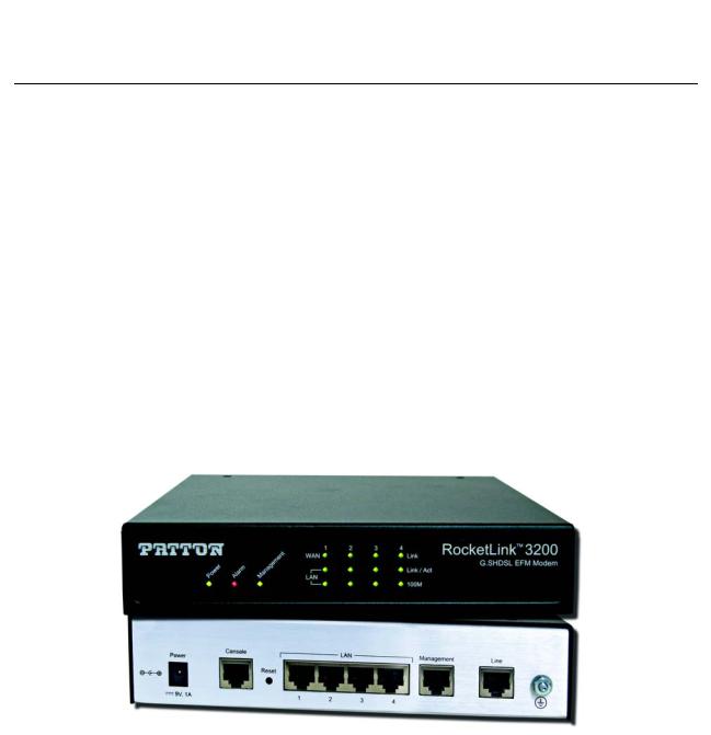
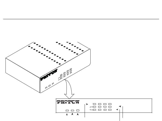
Figure 1. Model 3202
The following base models are available:
•3202/2W/EUI: G.SHDSL 2Base-TL EFM Modem (2-wire), 5.7 Mbps
•3202/4W/EUI: G.SHDSL 2Base-TL EFM Modem (4-wire), 11.4 Mbps
•3202/8W/EUI: G.SHDSL 2Base-TL EFM Modem (8-wire), 22.8 Mbps
Refer to Appendix B, “Specifications” on page 102 for a complete feature description of the Model 3202.
Model 3202 overview |
18 |
Model 3202 Getting Started Guide |
1 • General information |
|
|
Model 3202 front panel
LED descriptions
The front panel LEDs display the status of the power, system, Ethernet ports, and Line port. Figure 2 shows the front panel LED indicators and table 2 provides a description of the LED indicators’ behavior.
|
|
|
|
3200 |
|
|
™ |
Modem |
|
RocketLink |
EFM |
|||
|
G |
.SHDSL |
|
|
|
|
|
|
|
4 |
LINK |
|
|
|
3 |
LINK/ACT |
|
|
|
2 |
100M |
|
|
|
|
|
|
|
|
1
WAN
LAN
DIAG
ALM
PWR
|
|
|
1 |
2 |
3 |
4 |
|
|
|
|
|
WAN |
|
|
|
|
|
|
PWR ALM DIAG |
|
LAN |
|||
|
|
||||
|
|
|
RocketLink™ 3200 |
|
LINK |
|
G.SHDSL EFM Modem |
||
LINK/ACT |
|
|
||
|
|
|||
100M |
|
|
|
|
|
|
|
||
|
|
|
|
|
|
|
WAN(1-4) Line Connection |
|
|
|
LAN (1-4) Ethernet Link/Activity |
||
|
|
|
|
|
|
|
|||||||
|
|
|
|
|
|
|
|
|
|
||||
|
|
Power |
Console |
|
|
LAN (1-4) Ethernet Mode |
|||||||
|
|
|
|||||||||||
|
|
|
|
|
|
|
|
|
|
|
|
|
|
|
|
|
Alarm |
|
|
|
|
|
|
|
|
|
|
|
Figure 2. Model 3202 front panel LEDs |
|
|
|
|||||||||
|
|
Table 2. Front panel LEDs |
|
|
|
||||||||
|
|
|
|
|
|
|
|
|
|
|
|
|
|
LED |
|
Condition |
|
|
Description |
|
|
|
|||||
|
|
|
|
|
|
|
|
|
|
|
|
|
|
PWR |
|
On |
Power is applied |
|
|
|
|||||||
ALM |
|
On |
DSL LINE connection dropped |
|
|
|
|||||||
|
|
Blink |
DSL LINE self-test |
|
|
|
|||||||
|
|
|
|
|
|
|
|
|
|
|
|
|
|
DIAG |
|
On |
Management port is connected |
|
|||||||||
WAN (1-4) LINK |
|
On |
DSL LINE is connected |
|
|
|
|||||||
|
|
Blink |
DSL LINE handshake/transmitted/received data |
||||||||||
|
|
|
|
|
|
|
|
|
|
|
|
|
|
LAN (1-4) LINK/ACT |
|
On |
Ethernet is connected |
|
|
|
|||||||
|
|
Blink |
Ethernet link transmitted/received data |
|
|||||||||
LAN (1-4)100M |
|
On |
LAN port is on 100M mode |
|
|
|
|||||||
|
|
Off |
LAN port is on 10M mode |
|
|
|
|||||||
|
|
|
|
|
|
|
|
|
|
|
|
|
|
Model 3202 front panel |
19 |
Model 3202 Getting Started Guide |
1 • General information |
|
|
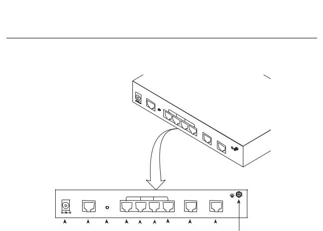
Model 3202 rear panel
Port descriptions
The RocketLink™ Model 3202 rear panel ports are shown in figure 3 and described in table 3.
DC |
9V |
|
CONSOLE
RST
LAN
1
2
3 |
MGMT |
4 |
LINE
DC 9V |
|
|
LAN |
|
|
|
CONSOLE |
|
|
MGMT |
LINE |
||
|
|
|
|
|||
|
|
RST |
|
|
|
|
+ |
- |
1 |
2 |
3 |
4 |
|
|
|
|
||||
|
|
|
|
|
|
|
|
|
|
|
|
|
|
Power |
|
Reset button |
|
|
|
|
Management |
|
Ground |
||||
|
|
|
|
|
|
|
|
|
|
RJ-45 port |
|
|
|
|
|
Console |
|
LAN (1-4) |
DSL |
||||||||
|
|
RS-232 port |
|
RJ-45 port |
RJ-45 port |
||||||||
|
|
|
|
Figure 3. Model 3202 rear panel |
|||||||||
|
|
|
|
|
|
Table 3. Port descriptions |
|
|
|||||
|
|
|
|
|
|
|
|
|
|
|
|
|
|
Port |
|
|
|
|
|
|
|
|
|
Description |
|||
|
|
|
|
|
|
|
|
|
|
|
|
|
|
DC 9V |
|
|
|
|
Power adaptor inlet: Input voltage 9VDC |
||||||||
Console (RS-232 control port) |
|
Used for service and maintenance, the Console port, an RS-232 |
|||||||||||
|
|
|
|
|
|
RJ-45 connector with EIA-561 pinout, connects the router to a |
|||||||
|
|
|
|
|
|
serial terminal such as a PC or ASCII terminal (also called a dumb |
|||||||
|
|
|
|
|
|
terminal). Asynchronous default data rate 9600 bps, hardware |
|||||||
|
|
|
|
|
|
DSR and DTR signals for external modems are wired directly |
|||||||
|
|
|
|
|
|
together internally |
|
|
|||||
|
|
|
|
|
|
|
|
|
|
|
|
|
|
RST |
|
|
|
|
Reset button for rebooting or loading factory default settings |
||||||||
LAN (LAN Ethernet Ports 1-4) |
|
10/100Base-Tx full-/half-duplex, RJ-45, auto detection and fall- |
|||||||||||
|
|
|
|
|
|
back, connects the unit to an Ethernet LAN. |
|||||||
|
|
|
|
|
|
|
|
|
|
|
|
|
|
MGMT |
|
|
|
|
RJ-45 for management port |
|
|
||||||
LINE |
|
|
|
|
G.SHDSL .Bis interface for WAN port (RJ-45) |
||||||||
|
|
|
|
|
|
|
|
|
|
|
|
|
|
Note For port pinout information, see Appendix C, “Port pin-outs” on page 105.
Model 3202 rear panel |
20 |
Model 3202 Getting Started Guide |
1 • General information |
|
|
Reset button
•To restart the unit with the current startup configuration—Press for less than 1 second and release the Reset button. The Model 3202 will restart with the current startup configuration.
•To restart the unit with factory default configuration—Press the Reset button for 5 seconds until the Power LED starts blinking. The unit will restart with factory default configuration.
•To restart the unit in bootloader mode (to be used only by trained RocketLink technicians)—Start with the unit powered off. Press and hold the Reset button while applying power to the unit. Release the Reset button when the Power LED starts blinking so the unit will enter bootloader mode.
Ground terminal
The marked lug or terminal should be connected to the building protective earth bus.The function of protective earth does not serve the purpose of providing protection against electrical shock, but instead enhances surge suppression on the DSL lines for installations where suitable bonding facilities exist.The connector type is M3 machine screw.
Model 3202 rear panel |
21 |

Chapter 2 Applications overview |
|
Chapter contents |
|
Introduction .......................................................................................................................................................... |
23 |
Typical application ................................................................................................................................................ |
23 |
Distance charts ...................................................................................................................................................... |
24 |
Distance Chart 3200 Series (Per Wire Pair) .................................................................................................... |
24 |
Distance Chart Model 3202/4W (4 Wire/2 Pair) ............................................................................................ |
24 |
Distance Chart Model 3202/8W (8 Wire/4 Pair) ............................................................................................ |
25 |
22

Model 3202 Getting Started Guide |
2 • Applications overview |
|
|
Introduction
The Model 3202 is Ethernet First Mile (EFM) compliant. EFM—also called pure Ethernet—lowers OPEX and CAPEX by resolving one of the biggest deficiencies in carrier networks, the lack of interworking arrangements among different protocols such as Frame Relay, TDM, ATM, and of course DSL. Using EFM allows for more efficient and trouble-free networking environments. Service providers can concentrate on providing differentiated services instead of concentrating on resolving their latest issue of protocol conversions.
Typical application
The Model 3202 G.SHDSL EFM modems are ideal for delivering remote network access for inter-office connectivity. Businesses can take advantage of the already installed copper infrastructure and pass up to 22.8 Mbps of symmetrical data reliably at distances of up to 1.8 miles (2.9 km).
Utilize pre-existing copper infrastructure for mobile backhaul to reduce Last Mile transport costs and to connect to new packet-switched networks.
Figure 4. Model 3202 application
Introduction |
23 |

Model 3202 Getting Started Guide 2 • Applications overview
Distance charts
Distance Chart 3200 Series (Per Wire Pair)
Table 4. Distance Chart 3202 Series (Per Wire Pair)
DSL Line Rate |
26 AWG/0.4mm |
24 AWG/0.5mm |
22 AWG/0.65mm |
||||
|
|
|
|
|
|
|
|
N |
kbps |
kft |
km |
kft |
km |
kft |
km |
|
|
|
|
|
|
|
|
3 |
192 |
21.5 |
6.6 |
27.2 |
8.3 |
34.8 |
10.6 |
4 |
256 |
19.5 |
5.9 |
24.7 |
7.5 |
31.5 |
9.6 |
8 |
512 |
17.5 |
5.3 |
22.1 |
6.7 |
28.3 |
8.6 |
12 |
768 |
16.5 |
5 |
20.9 |
6.4 |
26.7 |
8.1 |
16 |
1024 |
16 |
4.9 |
20.2 |
6.2 |
25.9 |
7.9 |
20 |
1280 |
15 |
4.6 |
19 |
5.8 |
24.3 |
7.4 |
24 |
1536 |
14.5 |
4.4 |
18.3 |
5.6 |
23.5 |
7.2 |
32 |
2048 |
13.5 |
4.1 |
17.1 |
5.2 |
21.8 |
6.6 |
36 |
2304 |
13 |
4 |
16.4 |
5 |
21 |
6.4 |
60 |
3840 |
10 |
3 |
12.6 |
3.8 |
16.2 |
4.9 |
72 |
4608 |
9.5 |
2.9 |
12 |
3.7 |
15.4 |
4.7 |
89 |
5696 |
8.5 |
2.6 |
10.8 |
3.3 |
13.8 |
4.2 |
|
|
|
|
|
|
|
|
Distance Chart Model 3202/4W (4 Wire/2 Pair)
Table 5. Distance Chart Model 3202/4W (4 Wire/2 Pair)
DSL Line Rate |
26 AWG/0.4mm |
24 AWG/0.5mm |
22 AWG/0.65mm |
||||
|
|
|
|
|
|
|
|
N |
kbps |
kft |
km |
kft |
km |
kft |
km |
|
|
|
|
|
|
|
|
6 |
512 |
19.5 |
5.9 |
24.7 |
7.5 |
31.5 |
9.6 |
8 |
512 |
19.5 |
5.9 |
24.7 |
7.5 |
31.5 |
9.6 |
16 |
1024 |
17.5 |
5.3 |
22.1 |
6.7 |
28.3 |
8.6 |
24 |
1536 |
16.5 |
5 |
20.9 |
6.4 |
26.7 |
8.1 |
32 |
2048 |
16 |
4.9 |
20.2 |
6.2 |
25.9 |
7.9 |
40 |
2560 |
15 |
4.6 |
19 |
5.8 |
24.3 |
7.4 |
48 |
3072 |
14.5 |
4.4 |
18.3 |
5.6 |
23.5 |
7.2 |
64 |
4096 |
13.5 |
4.1 |
17.1 |
5.2 |
21.8 |
6.6 |
72 |
4608 |
13 |
4 |
16.4 |
5 |
21 |
6.4 |
120 |
7680 |
10 |
3 |
12.6 |
3.8 |
16.2 |
4.9 |
144 |
9216 |
9.5 |
2.9 |
12 |
3.7 |
15.4 |
4.7 |
178 |
11392 |
8.5 |
2.6 |
10.8 |
3.3 |
13.8 |
4.2 |
|
|
|
|
|
|
|
|
Distance charts |
24 |

Model 3202 Getting Started Guide 2 • Applications overview
Distance Chart Model 3202/8W (8 Wire/4 Pair)
Table 6. Distance Chart Model 3202/8W (8 Wire/4 Pair)
DSL Line Rate |
26 AWG/0.4mm |
24 AWG/0.5mm |
22 AWG/0.65mm |
||||
|
|
|
|
|
|
|
|
N |
kbps |
kft |
km |
kft |
km |
kft |
km |
|
|
|
|
|
|
|
|
12 |
768 |
21.5 |
6.6 |
27.2 |
8.3 |
34.8 |
10.6 |
16 |
1024 |
19.5 |
5.9 |
24.7 |
7.5 |
31.5 |
9.6 |
32 |
2048 |
17.5 |
5.3 |
22.1 |
6.7 |
28.3 |
8.6 |
48 |
3072 |
16.5 |
5 |
20.9 |
6.4 |
26.7 |
8.1 |
64 |
4096 |
16 |
4.9 |
20.2 |
6.2 |
25.9 |
7.9 |
80 |
5120 |
15 |
4.6 |
19 |
5.8 |
24.3 |
7.4 |
96 |
6144 |
14.5 |
4.4 |
18.3 |
5.6 |
23.5 |
7.2 |
128 |
8192 |
13.5 |
4.1 |
17.1 |
5.2 |
21.8 |
6.6 |
144 |
9216 |
13 |
4 |
16.4 |
5 |
21 |
6.4 |
240 |
15360 |
10 |
3 |
12.6 |
3.8 |
16.2 |
4.9 |
288 |
18432 |
9.5 |
2.9 |
12 |
3.7 |
15.4 |
4.7 |
356 |
22784 |
8.5 |
2.6 |
10.8 |
3.3 |
13.8 |
4.2 |
|
|
|
|
|
|
|
|
Distance charts |
25 |

Chapter 3 |
Hardware installation |
|
Chapter contents |
|
|
Introduction .......................................................................................................................................................... |
|
27 |
Planning the installation........................................................................................................................................ |
27 |
|
Network diagram ............................................................................................................................................ |
28 |
|
IP related information ..................................................................................................................................... |
28 |
|
AC Power Mains ............................................................................................................................................. |
28 |
|
Location and mounting requirements ............................................................................................................. |
29 |
|
Installing the Model 3202 ..................................................................................................................................... |
29 |
|
Unpacking the Model 3202 ............................................................................................................................ |
29 |
|
Connecting cables ........................................................................................................................................... |
29 |
|
Grounding the Model 3202 and connecting power ......................................................................................... |
30 |
|
Configuring the Model 3202................................................................................................................................. |
31 |
|
Web configuration requirements ..................................................................................................................... |
31 |
|
Console configuration requirements ............................................................................................................... |
31 |
|
Telnet configuration requirements .................................................................................................................. |
31 |
|
26

Model 3202 Getting Started Guide |
3 • Hardware installation |
|
|
Introduction
This chapter contains information for planning the installation of the Model 3202 with the following installation procedures:
•“Unpacking the Model 3202” on page 29 lists the contents of the shipping box
•“Connecting cables” on page 29 describes how to install the port cables
•“Grounding the Model 3202 and connecting power” on page 30 describes how to ground and connect the power source
Planning the installation
Before beginning the actual installation, we strongly recommend that you gather all the information you will need to install and set up the device.
•Create a network diagram
•Gather IP related information
•Install the hardware and software needed to configure the Model 3202
•Verify power source reliability
When you finish preparing for your installation, go to section “Installing the Model 3202” on page 29 to install the device.
Introduction |
27 |
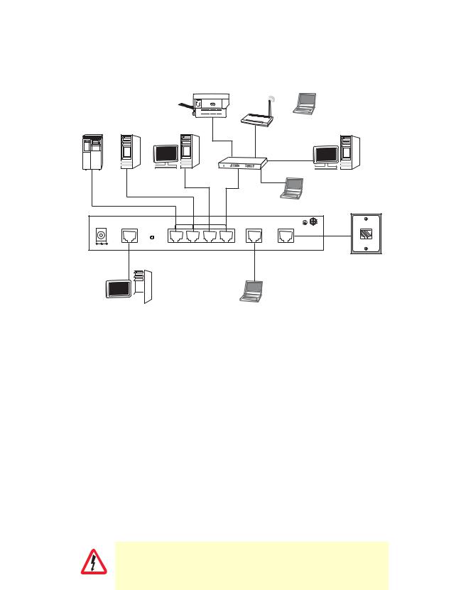
Model 3202 Getting Started Guide |
3 • Hardware installation |
|
|
Network diagram
Draw a network overview diagram that displays all neighboring IP nodes, connected elements and telephony components. Figure 5 shows possible network connections to the Model 3202.
Printer
WAP
Notebook
RAID Drive |
Server |
|
Desktop PC |
|
|
|
Switch |
Desktop PC |
|
|
|
|
|
Notebook |
|
DC 9V |
|
LAN |
|
||
CONSOLE |
MGMT |
LINE |
|||
|
|
||||
|
|
|
RST |
|
|
+ |
- |
|
LAN |
|
|
|
|
|
|
||
|
|
|
|
|
|
|
|
|
|
|
|
|
|
|
|
|
|
|
|
|
|
|
|
|
|
|
|
|
|
|
|
|
|
|
|
|
|
|
|
|
|
|
|
|
|
Desktop PC |
Laptop computer |
||||||
Figure 5. Model 3202 connection diagram
IP related information
Before you can set up the basic IP connectivity for your Model 3202 series you should have the following information:
•IP addresses used for Ethernet LAN and WAN ports
•Subnet mask used for Ethernet LAN and WAN ports
You will need a PC (or equivalent) with a VT-100 emulation program (e.g. HyperTerminal) to configure the software on your Model 3202.
AC Power Mains
If you suspect that your AC power is not reliable, for example if room lights flicker often or there is machinery with large motors nearby, have a qualified professional test the power. Install a power conditioner if necessary. Refer to “Grounding the Model 3202 and connecting power” on page 30.
The mains outlet that is utilized to power the equipment must be within 1 foot (3 meters) of the device and shall be easily accessible.
WARNING
Planning the installation |
28 |
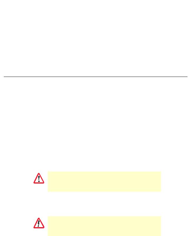
Model 3202 Getting Started Guide |
3 • Hardware installation |
|
|
Note When setting up your Model 3202 you must consider cable-length limitations and potential electromagnetic interference (EMI) as defined by the applicable local and international regulations. Ensure that your site is properly prepared before beginning installation.
Location and mounting requirements
The Model 3202 is intended to be placed on a desktop or similar sturdy, flat surface that offers easy access to the cables. Additionally, you should consider the need to access the unit for future upgrades and maintenance.
This completes the planning phase for installation. The next section begins the installation procedures.
Installing the Model 3202
Unpacking the Model 3202
Inspect the shipping carton for external damage. Note any damage before removing the container contents. Report any equipment damage to the shipping carrier immediately for claim purposes. Save all packing material in case you need to return an item to the factory for servicing.
The Model 3202 comes with the following items:
•Model 3202 Quick Start Guide
•Model 3202
•An RJ-45-to-RJ-45 cable for use with the console and Ethernet ports
•A DB-9-to-RJ-45 (EIA-561) adapter for connecting a PC’s serial port to the Model 3202 console port
•CD-ROM containing product literature and the Model 3202 Getting Started Guide
Note Power cables are shipped separately from the Model 3202
Connecting cables
The Interconnecting cables must be acceptable for external use and must be rated for the proper application with respect to voltage, current, anticipated temperature, flammability, and
CAUTION |
mechanical serviceability. |
|
1.Connect the Ethernet cable to the MGMT port. Model 3202 supports audi-MDIX switching so you may use a crossover or straight-through cable.
2.Connect one end of a phone cable to the LINE port and the other end of the cable to a wall jack.
Do not work on the system or connect or disconnect cables during periods of lightning activity.
WARNING
Installing the Model 3202 |
29 |
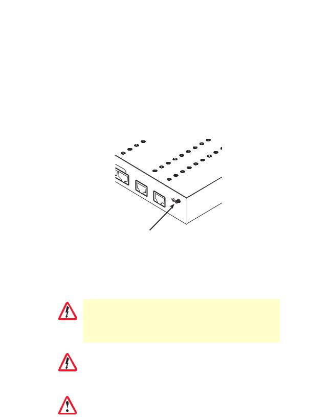
Model 3202 Getting Started Guide |
3 • Hardware installation |
|
|
Grounding the Model 3202 and connecting power
In connecting to the power source, it is important to establish a good grounding connection first, then the power connection. Do the following:
1.Assemble a ground wire using #10 AWG wire with green-colored insulation and two ring terminals. Make the wire long enough to reach one of the following earth ground sources:
–The building ground rod (generally located at the site’s main service entrance)
–A sprinkler system pipe
–A cold-water pipe
–Building structural steel
4 |
MGMT |
LINE
Grounding stud
Figure 6. Grounding stud
2.Install the grounding wire between the grounding stud (see figure 6) and the grounding source.
3.Connect the power adapter to the DC 9V port on the Model 3202, and then connect to the power source.
Mains Voltage: Do not open the case the when the power cord is attached. Line voltages are present within the power supply when the power cords are connected. The mains outlet that is utilized to power the device shall be within
WARNING |
10 feet (3 meters) of the device, shall be easily accessible, and protected by a |
|
|
||
|
circuit breaker. |
|
|
|
|
|
The Model 3202 is not shipped with power cables. For AC powered units, |
|
|
ensure that the power cable used meets all applicable standards for the coun- |
|
WARNING |
try in which it is to be installed, and that it is connected to a wall outlet which |
|
has earth ground. |
||
|
||
|
|
|
|
The power supply automatically adjusts to accept an input volt- |
|
|
age from 100 to 240 VAC(50/60 Hz). |
|
IMPORTANT |
|
|
|
|
Installing the Model 3202 |
30 |
Loading...