


 Loading...
CopperLink Model 1314
Long Range Ethernet Extender
User Manual
Important
This is a Class A device and is intended for use in a light industrial environment. It is not intended nor approved for use in an industrial or residential environment.
REGULATORY MODEL NUMBER: 03340D4-001
Sales Office: +1 (301) 975-1000
Technical Support: +1 (301) 975-1007
E-mail: support@patton.com
WWW: www.patton.com
Part Number: 07MCL1314, Rev. C
Revised: August 10, 2012
Patton Electronics Company, Inc.
7622 Rickenbacker Drive
Gaithersburg, MD 20879 USA
Tel: +1 (301) 975-1000
Fax: +1 (301) 869-9293
Support: +1 (301) 975-1007 Web: www.patton.com E-mail: support@patton.com
Trademark Statement
The term CopperLink is a trademark of Patton Electronics Company. All other trademarks presented in this document are the property of their respective owners.
Copyright © 2012, Patton Electronics Company. All rights reserved.
The information in this document is subject to change without notice. Patton Electronics assumes no liability for errors that may appear in this document.
Warranty Information
Patton Electronics warrants all Model CL1314 components to be free from defects, and will—at our option—repair or replace the product should it fail within one year from the first date of shipment.
This warranty is limited to defects in workmanship or materials, and does not cover customer damage, abuse or unauthorized modification. If this product fails or does not perform as warranted, your sole recourse shall be repair or replacement as described above. Under no condition shall Patton Electronics be liable for any damages incurred by the use of this product. These damages include, but are not limited to, the following: lost profits, lost savings and incidental or consequential damages arising from the use of or inability to use this product. Patton Electronics specifically disclaims all other warranties, expressed or implied, and the installation or use of this product shall be deemed an acceptance of these terms by the user.
Note Conformity documents of all Patton products can be viewed online at www.patton.com under the appropriate product page.

Summary Table of Contents |
|
|
1 |
General information ...................................................................................................................................... |
13 |
2 |
Configuration................................................................................................................................................ |
16 |
3 |
CopperLink installation ................................................................................................................................ |
24 |
4 |
Operation ...................................................................................................................................................... |
27 |
5 |
Software Upgrade .......................................................................................................................................... |
29 |
6 |
Contacting Patton for assistance ................................................................................................................... |
31 |
A |
Compliance information .............................................................................................................................. |
34 |
B |
Specifications ................................................................................................................................................ |
36 |
C |
Factory replacement parts and accessories .................................................................................................... |
40 |
D |
Interface pinouts .......................................................................................................................................... |
42 |
3

Table of Contents |
|
|
|
Summary Table of Contents ........................................................................................................................... |
3 |
|
Table of Contents ........................................................................................................................................... |
4 |
|
List of Figures ................................................................................................................................................. |
7 |
|
List of Tables .................................................................................................................................................. |
8 |
|
About this guide ............................................................................................................................................. |
9 |
|
Audience................................................................................................................................................................. |
9 |
|
Structure................................................................................................................................................................. |
9 |
|
Precautions ........................................................................................................................................................... |
10 |
|
Safety when working with electricity ............................................................................................................... |
11 |
|
General observations ....................................................................................................................................... |
12 |
|
Typographical conventions used in this document................................................................................................ |
12 |
|
General conventions ....................................................................................................................................... |
12 |
1 |
General information ...................................................................................................................................... |
13 |
|
CopperLink Model 1314 overview ........................................................................................................................ |
14 |
|
Features ................................................................................................................................................................. |
14 |
|
Power input connector .......................................................................................................................................... |
15 |
|
External AC universal power supply ................................................................................................................ |
15 |
|
External 48 VDC power supply ...................................................................................................................... |
15 |
2 |
Configuration................................................................................................................................................ |
16 |
|
Introduction .......................................................................................................................................................... |
17 |
|
Hardware (DIP-switch) configuration ............................................................................................................. |
17 |
|
Configuring the DIP switches ......................................................................................................................... |
17 |
|
DIP switch settings ......................................................................................................................................... |
18 |
|
DIP switch settings: Data Rate ........................................................................................................................ |
19 |
|
Ethernet Management Port ............................................................................................................................. |
22 |
|
CopperLink Status Command .................................................................................................................. |
22 |
|
Help Commands ....................................................................................................................................... |
22 |
|
Example Command Line Interface Session ................................................................................................ |
23 |
3 |
CopperLink installation ................................................................................................................................ |
24 |
|
Installation ............................................................................................................................................................ |
25 |
|
Connecting the CopperLink interface ............................................................................................................. |
25 |
|
Connecting the Ethernet interface .................................................................................................................. |
26 |
|
Connecting power ........................................................................................................................................... |
26 |
|
External AC universal power supply .......................................................................................................... |
26 |
|
DC Power ................................................................................................................................................. |
26 |
4 |
Operation ...................................................................................................................................................... |
27 |
|
Introduction .......................................................................................................................................................... |
28 |
|
Power-up ........................................................................................................................................................ |
28 |
|
LED status monitors ....................................................................................................................................... |
28 |
4

CopperLink Model 1314 User Manual |
Table of Contents |
|
|
|
Power (Green) ........................................................................................................................................... |
28 |
|
Link (Green) ............................................................................................................................................. |
28 |
|
ETH Activity (Green) ............................................................................................................................... |
28 |
|
ETH Link (Green) .................................................................................................................................... |
28 |
5 |
Software Upgrade .......................................................................................................................................... |
29 |
|
Introduction .......................................................................................................................................................... |
30 |
6 Contacting Patton for assistance ................................................................................................................... |
31 |
|
|
Introduction .......................................................................................................................................................... |
32 |
|
Contact information.............................................................................................................................................. |
32 |
|
Patton support headquarters in the USA ......................................................................................................... |
32 |
|
Alternate Patton support for Europe, Middle East, and Africa (EMEA) .......................................................... |
32 |
|
Warranty Service and Returned Merchandise Authorizations (RMAs)................................................................... |
32 |
|
Warranty coverage .......................................................................................................................................... |
32 |
|
Out-of-warranty service ............................................................................................................................. |
33 |
|
Returns for credit ...................................................................................................................................... |
33 |
|
Return for credit policy ............................................................................................................................. |
33 |
|
RMA numbers ................................................................................................................................................ |
33 |
|
Shipping instructions ................................................................................................................................ |
33 |
A |
Compliance information .............................................................................................................................. |
34 |
|
Compliance ........................................................................................................................................................... |
35 |
|
EMC ............................................................................................................................................................... |
35 |
|
Safety .............................................................................................................................................................. |
35 |
|
Radio and TV Interference (FCC Part 15) ............................................................................................................ |
35 |
|
CE Declaration of Conformity .............................................................................................................................. |
35 |
|
Authorized European Representative ..................................................................................................................... |
35 |
B |
Specifications ................................................................................................................................................ |
36 |
|
Line rate ................................................................................................................................................................ |
37 |
|
Ethernet interface .................................................................................................................................................. |
37 |
|
Status LEDs........................................................................................................................................................... |
37 |
|
Power (Green) ........................................................................................................................................... |
37 |
|
Link (Green) ............................................................................................................................................. |
37 |
|
ETH Activity (Green) ............................................................................................................................... |
37 |
|
ETH Link (Green) .................................................................................................................................... |
37 |
|
Configuration........................................................................................................................................................ |
37 |
|
Power and power supply specifications .................................................................................................................. |
38 |
|
External AC universal power supply ................................................................................................................ |
38 |
|
External 48 VDC power supply ...................................................................................................................... |
38 |
|
Transmission line .................................................................................................................................................. |
39 |
|
Line coding ........................................................................................................................................................... |
39 |
|
Line interface......................................................................................................................................................... |
39 |
|
CopperLink physical connection ........................................................................................................................... |
39 |
|
Environment ......................................................................................................................................................... |
39 |
5

CopperLink Model 1314 User Manual |
Table of Contents |
|
|
Third party software licenses.................................................................................................................................. |
39 |
C Factory replacement parts and accessories .................................................................................................... |
40 |
Factory replacement parts and accessories .............................................................................................................. |
41 |
D Interface pinouts .......................................................................................................................................... |
42 |
Line port ............................................................................................................................................................... |
43 |
Ethernet port......................................................................................................................................................... |
43 |
6

List of Figures
1 CopperLink Model 1314 . . . . . . . . . . . . . . . . . . . . . . . . . . . . . . . . . . . . . . . . . . . . . . . . . . . . . . . . . . . . . . . . . 14 2 Power connection barrel receptacle 5 VDC diagram . . . . . . . . . . . . . . . . . . . . . . . . . . . . . . . . . . . . . . . . . . . . . 15 3 Underside of CL1314 showing location of DIP switches . . . . . . . . . . . . . . . . . . . . . . . . . . . . . . . . . . . . . . . . . 18 4 CL1314 rear panel . . . . . . . . . . . . . . . . . . . . . . . . . . . . . . . . . . . . . . . . . . . . . . . . . . . . . . . . . . . . . . . . . . . . . . 25 5 DC Power Supply . . . . . . . . . . . . . . . . . . . . . . . . . . . . . . . . . . . . . . . . . . . . . . . . . . . . . . . . . . . . . . . . . . . . . . . 26 6 CL1314 front panel . . . . . . . . . . . . . . . . . . . . . . . . . . . . . . . . . . . . . . . . . . . . . . . . . . . . . . . . . . . . . . . . . . . . . 28 7 Power connection barrel receptacle 5 VDC diagram . . . . . . . . . . . . . . . . . . . . . . . . . . . . . . . . . . . . . . . . . . . . . 38
7

List of Tables
1 General conventions . . . . . . . . . . . . . . . . . . . . . . . . . . . . . . . . . . . . . . . . . . . . . . . . . . . . . . . . . . . . . . . . . . . . . 12 2 CopperLink configurable parameters . . . . . . . . . . . . . . . . . . . . . . . . . . . . . . . . . . . . . . . . . . . . . . . . . . . . . . . . 17 3 S4-2 through S4-8 Data Rate DIP switch settings . . . . . . . . . . . . . . . . . . . . . . . . . . . . . . . . . . . . . . . . . . . . . . . 19 4 RJ45 socket 10/100Base-T . . . . . . . . . . . . . . . . . . . . . . . . . . . . . . . . . . . . . . . . . . . . . . . . . . . . . . . . . . . . . . . . 43
8

About this guide
This guide describes installing and operating the Patton Electronics CopperLink™ Model 1314 Long Range Ethernet Extender.
Audience
This guide is intended for the following users:
•Operators
•Installers
•Maintenance technicians
Structure
This guide contains the following chapters and appendices:
•Chapter 1 on page 13 provides information about CL1314 features and capabilities
•Chapter 2 on page 16 provides information for configuring the CL1314
•Chapter 3 on page 24 describes how to install the CL1314
•Chapter 4 on page 27 describes how to operate the CL1314
•Chapter 5 on page 29 describes how to upgrade the system software
•Chapter 6 on page 31 contains information on contacting Patton technical support for assistance
•Appendix A on page 34 contains compliance information for the CL1314
•Appendix B on page 36 contains specifications for the CL1314
•Appendix C on page 40 provides cable recommendations
•Appendix D on page 42 describes the CL1314’s ports and pin-outs
For best results, read the contents of this guide before you install the CL1314.
9
CopperLink Model 1314 User Manual
Precautions
Notes, cautions, and warnings, which have the following meanings, are used throughout this guide to help you become aware of potential problems. Warnings are intended to prevent safety hazards that could result in personal injury. Cautions are intended to prevent situations that could result in property damage or
impaired functioning.
Note A note presents additional information or interesting sidelights.
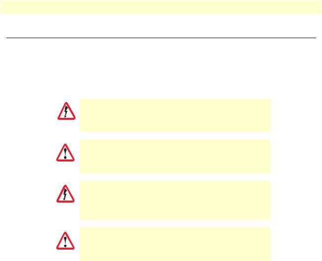
The shock hazard symbol and WARNING heading indicate a potential electric shock hazard. Strictly follow the warning instructions to avoid injury caused
by electric shock.
WARNING
The alert symbol and WARNING heading indicate a potential safety hazard.
Strictly follow the warning instructions to avoid personal injury.
WARNING
The shock hazard symbol and CAUTION heading indicate a potential electric shock hazard. Strictly follow the instructions to
avoid property damage caused by electric shock.
CAUTION
The alert symbol and CAUTION heading indicate a potential hazard. Strictly follow the instructions to avoid property damage.
CAUTION
10
CopperLink Model 1314 User Manual
Safety when working with electricity
•Do not open the device when the power cord is connected. For systems without a power switch and without an external power adapter, line voltages are present within the device when the power cord is connected.
WARNING
•For devices with an external power adapter, the power adapter shall be a listed imited Power Source The mains outlet that is utilized to power the device shall be within 10 feet (3 meters) of the device, shall be easily accessible, and protected by a circuit breaker in compliance with local regulatory requirements.
•For AC powered devices, ensure that the power cable used meets all applicable standards for the country in which it is to be installed.
•For AC powered devices which have 3 conductor power plugs (L1, L2 & GND or Hot, Neutral & Safety/Protective Ground), the wall outlet (or socket) must have an earth ground.
•For DC powered devices, ensure that the interconnecting cables are rated for proper voltage, current, anticipated temperature, flammability, and mechanical serviceability.
•WAN, LAN & PSTN ports (connections) may have hazardous voltages present regardless of whether the device is powered ON or OFF. PSTN relates to interfaces such as telephone lines, FXS, FXO, DSL, xDSL, T1, E1, ISDN, Voice, etc. These are known as “hazardous network voltages” and to avoid electric shock use caution when working near these ports. When disconnecting cables for these ports, detach the far end connection first.
•Do not work on the device or connect or disconnect cables during periods of lightning activity.
This device contains no user serviceable parts. This device can only be repaired by qualified service personnel.
WARNING
This device is NOT intended nor approved for connection to the PSTN. It is intended only for connection to customer premise equipment.
WARNING
In accordance with the requirements of council directive 2002/ 96/EC on Waste of Electrical and Electronic Equipment (WEEE), ensure that at end-of-life you separate this product from other waste and scrap and deliver to the WEEE collection system in your country for recycling.
11

CopperLink Model 1314 User Manual
Electrostatic Discharge (ESD) can damage equipment and impair electrical circuitry. It occurs when electronic printed circuit cards are improperly handled and can result in complete or intermittent
CAUTION failures. Do the following to prevent ESD:
•Always follow ESD prevention procedures when removing and replacing cards.
•Wear an ESD-preventive wrist strap, ensuring that it makes good skin contact. Connect the clip to an unpainted surface of the chassis frame to safely channel unwanted ESD voltages to ground.
•To properly guard against ESD damage and shocks, the wrist strap and cord must operate effectively. If no wrist strap is available, ground yourself by touching the metal part of the chassis.
General observations
•Clean the case with a soft slightly moist anti-static cloth
•Place the unit on a flat surface and ensure free air circulation
•Avoid exposing the unit to direct sunlight and other heat sources
•Protect the unit from moisture, vapors, and corrosive liquids
Typographical conventions used in this document
This section describes the typographical conventions and terms used in this guide.
General conventions
The procedures described in this manual use the following text conventions:
|
|
Table 1. General conventions |
|
|
|
|
|
Convention |
|
|
Meaning |
|
|
|
|
Garamond blue type |
Indicates a cross-reference hyperlink that points to a figure, graphic, table, or sec- |
||
|
tion heading. Clicking on the hyperlink jumps you to the reference. When you |
||
|
have finished reviewing the reference, click on the Go to Previous View |
||
|
button |
|
in the Adobe® Acrobat® Reader toolbar to return to your starting point. |
|
|
||
|
|
|
|
Futura bold type |
Commands and keywords are in boldface font. |
||
|
|
|
|
Futura bold-italic type |
Parts of commands, which are related to elements already named by the user, are |
||
|
in boldface italic font. |
||
Italicized Futura type |
Variables for which you supply values are in italic font |
||
|
|
|
|
Futura type |
Indicates the names of fields or windows. |
||
Garamond bold type |
Indicates the names of command buttons that execute an action. |
||
|
|
|
|
12

Chapter 1 General information |
|
Chapter contents |
|
CopperLink Model 1314 overview ........................................................................................................................ |
14 |
Features ................................................................................................................................................................. |
14 |
Power input connector .......................................................................................................................................... |
15 |
External AC universal power supply ................................................................................................................ |
15 |
External 48 VDC power supply ...................................................................................................................... |
15 |
13
Loading...