


 Loading...
Model 1195/4E1
Optical Multiplexer
Getting Started Guide
Sales Office: +1 (301) 975-1000
Technical Support: +1 (301) 975-1007
E-mail: support@patton.com
WWW: www.patton.com
Part Number: 07M1195-GS, Rev. A
Revised: February 12, 2009
Patton Electronics Company, Inc.
7622 Rickenbacker Drive
Gaithersburg, MD 20879 USA
Tel: +1 (301) 975-1000
Fax: +1 (301) 869-9293
Support: +1 (301) 975-1007 Web: www.patton.com E-mail: support@patton.com
Copyright © 2009, Patton Electronics Company. All rights reserved.
The information in this document is subject to change without notice. Patton Electronics assumes no liability for errors that may appear in this document.
Warranty Information
The software described in this document is furnished under a license and may be used or copied only in accordance with the terms of such license.
Patton Electronics warrants all 1195 components to be free from defects, and will—at our option—repair or replace the product should it fail within one year from the first date of the shipment.
This warranty is limited to defects in workmanship or materials, and does not cover customer damage, abuse or unauthorized modification. If the product fails to perform as warranted, your sole recourse shall be repair or replacement as described above. Under no condition shall Patton Electronics be liable for any damages incurred by the use of this product. These damages include, but are not limited to, the following: lost profits, lost savings and incidental or consequential damages arising from the use of or inability to use this product. Patton Electronics specifically disclaims all other warranties, expressed or implied, and the installation or use of this product shall be deemed an acceptance of these terms by the user.

Summary Table of Contents
1 |
General information........................................................................................................................................... |
13 |
2 |
Applications overview ........................................................................................................................................ |
21 |
3 |
Model 1195/4E1 installation.............................................................................................................................. |
23 |
4 |
Connecting the RS-232 port .............................................................................................................................. |
29 |
5 |
CLI configuration............................................................................................................................................... |
34 |
6 |
GUI configuration .............................................................................................................................................. |
47 |
7 |
Contacting Patton for assistance....................................................................................................................... |
66 |
A |
Specifications ..................................................................................................................................................... |
69 |
B |
Connector pinouts ............................................................................................................................................. |
74 |
3

Table of Contents |
|
|
|
Safety when working with electricity ............................................................................................................ |
11 |
|
General observations ..................................................................................................................................... |
11 |
|
General conventions ...................................................................................................................................... |
12 |
1 |
General information........................................................................................................................................... |
13 |
|
Model 1195/4E1 Overview................................................................................................................................... |
14 |
|
Features and Benefits ........................................................................................................................................... |
14 |
|
Front View............................................................................................................................................................ |
15 |
|
Rear View............................................................................................................................................................. |
20 |
2 |
Applications overview ........................................................................................................................................ |
21 |
|
Typical Model 1195/4E1 Application......... ........................................................................................................ |
22 |
3 |
Model 1195/4E1 installation.............................................................................................................................. |
23 |
|
Connecting power ................................................................................................................................................ |
24 |
|
AC Power ....................................................................................................................................................... |
24 |
|
DC Power ....................................................................................................................................................... |
24 |
|
Grounding ...................................................................................................................................................... |
25 |
|
Connecting the optical interface........................................................................................................................... |
26 |
|
Connecting the DB-37 connector......................................................................................................................... |
27 |
|
Connecting E1 links ............................................................................................................................................. |
28 |
|
Definition for E1 Interfaces ........................................................................................................................... |
28 |
|
Connecting Ethernet Links................................................................................................................................... |
28 |
|
Verifying the connection ............................................................................................................................... |
28 |
|
Definition for Ethernet Interfaces .................................................................................................................. |
28 |
4 Connecting the RS-232 port .............................................................................................................................. |
29 |
|
|
Connecting the RS-232 port................................................................................................................................. |
30 |
|
RS-232 port cable details ............................................................................................................................... |
31 |
|
RS-232 pin definition .................................................................................................................................... |
31 |
|
Configuring HyperTerminal................................................................................................................................. |
32 |
5 |
CLI configuration............................................................................................................................................... |
34 |
|
General Commands.............................................................................................................................................. |
35 |
|
Specific Commands.............................................................................................................................................. |
37 |
|
Check current MAC address of the device .................................................................................................... |
37 |
|
Check the current IP address of the device .................................................................................................... |
37 |
|
Check gateway address of the device ............................................................................................................ |
37 |
|
View the get / getnext community of SNMP ................................................................................................. |
37 |
|
Configure the get / getnext community of SNMP ......................................................................................... |
37 |
|
View the set community of SNMP ................................................................................................................ |
38 |
|
Configure set community of SNMP .............................................................................................................. |
38 |
|
Change the IP address of the device .............................................................................................................. |
38 |
|
Change the Subnet mask information of the device ...................................................................................... |
38 |
4

Model 1195 Getting Started Guide |
Table of Contents |
|
|
Change the Gateway information of the device ............................................................................................ |
38 |
Change the MAC address of the device ........................................................................................................ |
39 |
Show system information .............................................................................................................................. |
39 |
Enable / Disable the loopback of E1 Port ...................................................................................................... |
40 |
Check whether the E1 Port is looped back .................................................................................................... |
40 |
Check the alarms of E1 Tributary .................................................................................................................. |
41 |
Configure laser port receive mode ................................................................................................................. |
41 |
View the current status of laser port .............................................................................................................. |
42 |
Reset the system ............................................................................................................................................ |
42 |
Set / configure the default settings in the device ........................................................................................... |
42 |
Enable / Disable the Ethernet Port ................................................................................................................. |
42 |
Set / configure the Ethernet Port performance parameters ............................................................................ |
43 |
Check the Ethernet Port configuration .......................................................................................................... |
43 |
View the performance of ethernet port .......................................................................................................... |
44 |
View the status of ethernet port ..................................................................................................................... |
44 |
Clear the performance statics / log of Ethernet, E1, GFP .............................................................................. |
44 |
Add a telnet user ............................................................................................................................................ |
45 |
Delete a Telnet user ....................................................................................................................................... |
45 |
Check the list of Telnet users ......................................................................................................................... |
45 |
View the status of remote system power ....................................................................................................... |
45 |
Mask the unused e1 alarms ............................................................................................................................ |
45 |
View the configuration of unused e1 alarm mask ......................................................................................... |
45 |
Clear the record of E1's CV alarm ................................................................................................................. |
46 |
Configure the status of alarm tone mask ....................................................................................................... |
46 |
View the status of alarm tone mask ............................................................................................................... |
46 |
6 GUI configuration .............................................................................................................................................. |
47 |
Overview .............................................................................................................................................................. |
48 |
Installing the GUI................................................................................................................................................. |
48 |
Accessing the 1195......... ..................................................................................................................................... |
49 |
Adding/Removing a System................................................................................................................................. |
49 |
Adding a system ............................................................................................................................................ |
49 |
Removing a system ........................................................................................................................................ |
50 |
Editing a system ............................................................................................................................................. |
50 |
Communicating With a System............................................................................................................................ |
51 |
Adding/Removing Users...................................................................................................................................... |
52 |
Adding a user ................................................................................................................................................. |
52 |
Removing a user ............................................................................................................................................ |
52 |
Editing a user entry ........................................................................................................................................ |
52 |
Status Monitoring................................................................................................................................................. |
53 |
System Monitoring............................................................................................................................................... |
54 |
Start/stop monitoring ..................................................................................................................................... |
54 |
Configure/view alarms ................................................................................................................................... |
54 |
Change the Trap Community and/or Port ...................................................................................................... |
54 |
5

Model 1195 Getting Started Guide
View log ............................................ |
...............................................................................................................55 |
|
Managing Trap Details......................................................................................................................................... |
|
55 |
Configuring System Settings................................................................................................................................ |
|
55 |
Configuring IP Settings........................................................................................................................................ |
|
56 |
Configuring Trap Settings.................................................................................................................................... |
|
57 |
Configuring Default Settings ............................................................................................................................... |
|
58 |
SNMP Community............................................................................................................................................... |
|
59 |
Viewing Settings .................................................................................................................................................. |
|
60 |
Back Up................................................................................................................................................................ |
|
61 |
Restore.................................................................................................................................................................. |
|
61 |
Synchronize.......................................................................................................................................................... |
|
62 |
Report................................................................................................................................................................... |
|
62 |
List of systems ............................................................................................................................................... |
|
62 |
List of traps .................................................................................................................................................... |
|
63 |
Read Me ............................................................................................................................................................... |
|
64 |
System Information.............................................................................................................................................. |
|
65 |
Exiting the System ............................................................................................................................................... |
|
65 |
7 Contacting Patton for assistance....................................................................................................................... |
|
66 |
Introduction .......................................................................................................................................................... |
|
67 |
Contact information.............................................................................................................................................. |
|
67 |
Patton support headquarters in the USA ........................................................................................................ |
67 |
|
Alternate Patton support for Europe, Middle East, and Africa (EMEA) ....................................................... |
67 |
|
Warranty Service and Returned Merchandise Authorizations (RMAs)............................................................... |
67 |
|
Warranty coverage ......................................................................................................................................... |
|
67 |
Out-of-warranty service ........................................................................................................................... |
|
68 |
Returns for credit ..................................................................................................................................... |
|
68 |
Return for credit policy ............................................................................................................................ |
|
68 |
RMA numbers ............................................................................................................................................... |
|
68 |
Shipping instructions ............................................................................................................................... |
|
68 |
A Specifications ..................................................................................................................................................... |
|
69 |
E1 Interface .......................................................................................................................................................... |
|
70 |
Optical .................................................................................................................................................................. |
|
70 |
Optical Interface Specifications: 1310nm Single Mode ...................................................................................... |
71 |
|
Transmitter Optical Characteristics |
............................................................................................................... |
71 |
Receiver Optical Characteristics .................................................................................................................... |
|
71 |
Optical Interface Specifications: 1550nm Single Mode ...................................................................................... |
71 |
|
Transmitter Optical Characteristics |
............................................................................................................... |
71 |
Receiver Optical Characteristics .................................................................................................................... |
|
72 |
Safety.................................................................................................................................................................... |
|
72 |
Ethernet Interface ................................................................................................................................................. |
|
72 |
Configuration, Management and Alarms............................................................................................................. |
72 |
|
Power Supply ....................................................................................................................................................... |
|
72 |
Environment......................................................................................................................................................... |
|
73 |
6

Model 1195 Getting Started Guide |
Table of Contents |
|
|
Physical ................................................................................................................................................................ |
73 |
B Connector pinouts ............................................................................................................................................. |
74 |
DB-37 connector pinout (Model 1195/4E1)......................................................................................................... |
75 |
DB-37 connector pinout details for E1 connections ...................................................................................... |
75 |
7

List of Figures
1 Model 1195/4E1 . . . . . . . . . . . . . . . . . . . . . . . . . . . . . . . . . . . . .. . . . . . . . . . . . . . . . . . . . . . . . . . . . . . . . . . . 14 2 1195/4E1 front view . . . . . . . . . . . . . . . . . . . . . . . . . . . . . . . . . . . . . . . . . . . . . . . . . . . . . . . . . . . . . . . . . . . . 15 3 Front LEDs . . . . . . . . . . . . . . . . . . . . . . . . . . . . . . . . . . . . . . . . . . . . . . . . . . . . . . . . . . . . . . . . . . . . . . . . . . . 16 4 Tributary Status LEDs . . . . . . . . . . . . . . . . . . . . . . . . . . . . . . . . . . . . . . . . . . . . . . . . . . . . . . . . . . . . . . . . . . . 17 5 Config Switch LEDs . . . . . . . . . . . . . . . . . . . . . . . . . . . . . . . . . . . . . . . . . . . . . . . . . . . . . . . . . . . . . . . . . . . . 18 6 Interfaces . . . . . . . . . . . . . . . . . . . . . . . . . . . . . . . . . . . . . . . . . . . . . . . . . . . . . . . . . . . . . . . . . . . . . . . . . . . . . 19 7 1195/4E1 rear view . . . . . . . . . . . . . . . . .. . . . . . . . . . . . . . . . . . . . . . . . . . . . . . . . . . . . . . . . . . . . . . . . . . . . . 20 8 Typical application for Model 1195/4E1 . . . . . . ... . . . . . . . . . . . . . . . . . . . . . . . . . . . . . . . . . . . . . . . . . . . . . 22 9 CD flash screen . . . . . . . . . . . . . . . . . . . . . . . . . . . . . . . . . . . . . . . . . . . . . . . . . . . . . . . . . . . . . . . . . . . . . . . . 48 10 Model 1195/4E1 Main Menu window . . . . . . . . . . . . ... . . . . . . . . . . . . . . . . . . . . . . . . . . . . . . . . . . . . . . . . . 49 11 Add/Remove System . . . . . . . . . . . . . . . . . . . . . . . . . . . . . . . . . . . . . . . . . . . . . . . . . . . . . . . . . . . . . . . . . . . . 50 12 Select COM port . . . . . . . . . . . . . . . . . . . . . . . . . . . . . . . . . . . . . . . . . . . . . . . . . . . . . . . . . . . . . . . . . . . . . . . 51 13 Select TCP/IP address . . . . . . . . . . . . . . . . . . . . . . . . . . . . . . . . . . . . . . . . . . . . . . . . . . . . . . . . . . . . . . . . . . . 51 14 Login . . . . . . . . . . . . . . . . . . . . . . . . . . . . . . . . . . . . . . . . . . . . . . . . . . . . . . . . . . . . . . . . . . . . . . . . . . . . . . . . 52 15 Add user . . . . . . . . . . . . . . . . . . . . . . . . . . . . . . . . . . . . . . . . . . . . . . . . . . . . . . . . . . . . . . . . . . . . . . . . . . . . . . 52 16 Status Monitoring . . . . . . . . . . . . . . . . . . . . . . . . . . . . . . . . . . . . . . . . . . . . . . . . . . . . . . . . . . . . . . . . . . . . . . 53 17 System Monitoring . . . . . . . . . . . . . . . . . . . . . . . . . . . . . . . . . . . . . . . . . . . . . . . . . . . . . . . . . . . . . . . . . . . . . 54 18 System settings . . . . . . . . . . . . . . . . . . . . . . . . . . . . . . . . . . . . . . . . . . . . . . . . . . . . . . . . . . . . . . . . . . . . . . . . 55 19 E1 settings . . . . . . . . . . . . . . . . . . . . . . . . . . . . . . . . . . . . . . . . . . . . . . . . . . . . . . . . . . . . . . . . . . . . . . . . . . . . 56 20 IP settings . . . . . . . . . . . . . . . . . . . . . . . . . . . . . . . . . . . . . . . . . . . . . . . . . . . . . . . . . . . . . . . . . . . . . . . . . . . . 57 21 Trap settings . . . . . . . . . . . . . . . . . . . . . . . . . . . . . . . . . . . . . . . . . . . . . . . . . . . . . . . . . . . . . . . . . . . . . . . . . . 57 22 Default settings . . . . . . . . . . . . . . . . . . . . . . . . . . . . . . . . . . . . . . . . . . . . . . . . . . . . . . . . . . . . . . . . . . . . . . . . 58 23 SNMP Community . . . . . . . . . . . . . . . . . . . . . . . . . . . . . . . . . . . . . . . . . . . . . . . . . . . . . . . . . . . . . . . . . . . . . 59 24 Show settings . . . . . . . . . . . . . . . . . . . . . . . . . . . . . . . . . . . . . . . . . . . . . . . . . . . . . . . . . . . . . . . . . . . . . . . . . . 60 25 Back up . . . . . . . . . . . . . . . . . . . . . . . . . . . . . . . . . . . . . . . . . . . . . . . . . . . . . . . . . . . . . . . . . . . . . . . . . . . . . . 61 26 Restore . . . . . . . . . . . . . . . . . . . . . . . . . . . . . . . . . . . . . . . . . . . . . . . . . . . . . . . . . . . . . . . . . . . . . . . . . . . . . . . 61 27 Synchronize . . . . . . . . . . . . . . . . . . . . . . . . . . . . . . . . . . . . . . . . . . . . . . . . . . . . . . . . . . . . . . . . . . . . . . . . . . . 62 28 View systems report . . . . . . . . . . . . . . . . . . . . . . . . . . . . . . . . . . . . . . . . . . . . . . . . . . . . . . . . . . . . . . . . . . . . 62 29 View traps . . . . . . . . . . . . . . . . . . . . . . . . . . . . . . . . . . . . . . . . . . . . . . . . . . . . . . . . . . . . . . . . . . . . . . . . . . . . 63 30 Readme file . . . . . . . . . . . . . . . . . . . . . . . . . . . . . . . . . . . . . . . . . . . . . . . . . . . . . . . . . . . . . . . . . . . . . . . . . . . 64 31 View system information . . . . . . . . . . . . . . . . . . . . . . . . . . . . . . . . . . . . . . . . . . . . . . . . . . . . . . . . . . . . . . . . 65 32 DB-37 connector pinout . . . . . . . . . . . . . . . . . . . . . . . . . . . . . . . . . . . . . . . . . . . . . . . . . . . . . . . . . . . . . . . . . 75
8

About this guide
This guide describes the Model 1195/4E1 hardware, installation and basic configuration.
Audience
This guide is intended for the following users:
•Operators
•Installers
•Maintenance technicians
Structure
This guide contains the following chapters and appendices:
•Chapter 1 on page 13 provides information about features and capabilities
•Chapter 2 on page 21 contains an overview describing the typical application
•Chapter 3 on page 23 provides hardware installation procedures
•Chapter 4 on page 29 provides information for connecting the RS-232 port
•Chapter 5 on page 34 provides information for using the CLI to configure the unit
•Chapter 6 on page 47 provides information for using the GUI to configure the unit
•Chapter 7 on page 66 contains information on contacting Patton technical support for assistance
•Appendix A on page 69 contains technical specifications
•Appendix B on page 74 describes the connector pin-outs
For best results, read the contents of this guide before you install the unit.
9
Precautions
Notes, cautions, and warnings, which have the following meanings, are used throughout this guide to help you become aware of potential problems. Warnings are intended to prevent safety hazards that could result in personal injury. Cautions are intended to prevent situations that could result in property damage or
impaired functioning.
Note A note presents additional information or interesting sidelights.
The alert symbol and IMPORTANT heading calls attention to important information.
IMPORTANT
The alert symbol and CAUTION heading indicate a potential hazard. Strictly follow the instructions to avoid property damage.
CAUTION
The shock hazard symbol and CAUTION heading indicate a potential electric shock hazard. Strictly follow the instructions to avoid property damage caused by electric shock.
CAUTION
The alert symbol and WARNING heading indicate a potential safety hazard.
Strictly follow the warning instructions to avoid personal injury.
WARNING
The shock hazard symbol and WARNING heading indicate a potential electric shock hazard. Strictly follow the warning instructions to avoid injury caused
by electric shock.
WARNING
10
Model 1195 Getting Started Guide
Safety when working with electricity
• This device contains no user serviceable parts. The equipment shall be returned to Patton Electronics for repairs, or repaired by qualified service
personnel.
WARNING
•Mains Voltage: Line voltages are present when the power cord is connected. The mains outlet shall be within 10 feet (3 meters) of the device, shall be easily accessible, and protected by a circuit breaker.
•For AC powered units, ensure that the power cable used meets all applicable standards for the country in which it is to be installed, and that it is connected to a wall outlet which has earth ground.
•Hazardous network voltages are present in WAN ports, regardless of whether power to the unit is ON or OFF. To avoid electric shock, use caution when near WAN ports. When detaching the cables, detach the end away from the unit first.
•Do not work on the system or connect or disconnect cables during periods of lightning activity.
•For units with an external power adapter, the adapter shall be a listed Limited Power Source.
In accordance with the requirements of council directive 2002/ 96/EC on Waste of Electrical and Electronic Equipment (WEEE), ensure that at end-of-life you separate this product from other waste and scrap and deliver to the WEEE collection system in your country for recycling.
General observations
•Place the unit on a flat surface and ensure free air circulation
•Avoid exposing the unit to direct sunlight and other heat sources
•Protect the unit from moisture, vapors, and corrosive liquids
11
Model 1195 Getting Started Guide
Typographical conventions used in this document
This section describes the typographical conventions and terms used in this guide.
General conventions
The procedures described in this manual use the following text conventions:
|
|
Table 1. General conventions |
|
|
|
Convention |
|
Meaning |
|
|
|
Garamond blue type |
Indicates a cross-reference hyperlink that points to a figure, graphic, table, or sec- |
|
|
tion heading. Clicking on the hyperlink jumps you to the reference. When you |
|
|
have finished reviewing the reference, click on the Go to Previous View |
|
|
button |
in the Adobe® Acrobat® Reader toolbar to return to your starting point. |
|
|
|
Futura bold type |
Commands and keywords are in boldface font. |
|
|
|
|
Futura bold-italic type |
Parts of commands, which are related to elements already named by the user, are |
|
|
in boldface italic font. |
|
|
|
|
Italicized Futura type |
Variables for which you supply values are in italic font |
|
|
|
|
Futura type |
Indicates the names of fields or windows. |
|
|
|
|
Garamond bold type |
Indicates the names of command buttons that execute an action. |
|
|
|
|
< > |
Angle brackets indicate function and keyboard keys, such as <SHIFT>, <CTRL>, |
|
|
<C>, and so on. |
|
|
|
|
[ ] |
Elements in square brackets are optional. |
|
|
|
|
{a | b | c} |
Alternative but required keywords are grouped in braces ({ }) and are separated |
|
|
by vertical bars ( | ) |
|
|
|
|
screen |
Terminal sessions and information the system displays are in screen font. |
|
|
|
|
node |
The leading IP address or nodename of a Model 1195 is substituted with |
|
|
node in boldface italic font. |
|
|
|
|
SN |
The leading SN on a command line represents the nodename of the Model 1195 |
|
|
|
|
# |
An hash sign at the beginning of a line indicates a comment line. |
|
|
|
|
12

Chapter 1 General information |
|
Chapter contents |
|
Model 1195.................................................................................................................................. |
14 |
Features and Benefits.................................................................................................................... |
14 |
Front View ................................................................................................................................... |
15 |
Rear View..................................................................................................................................... |
20 |
13
Model 1195 Getting Started Guide |
1 • General information |
|
|
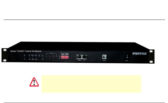
Model 1195/4E1
Model 1195 FiberLink E1/Ethernet Mux is a point to point high performance optical line transmission equipment, combines 8, ITU-T G.703 compliant standard electrical E1s plus 100BaseT Ethernet signal into an optical data stream for transport over fiber optic pairs. Several transmitter options for different cable types and wave-lengths are available. 1+1 optical path redundancy is offered and available as an option.
Figure 1. Model 1195/4E1
For Testing: Always Install Optical Attenuators. For distances of less than 10
km, optical attentuators must be intalled on the Optical Links. Otherwise, the
optics will be permanently damaged.
WARNING
Features and Benefits
•Integrated E1 Plus Ethernet Optical Multiplexer
•Compact design that performs E1 and Ethernet channel multiplexing & de-multiplexing to an optical output
•Provides visible and audible alarm indication
•Provide Remote power detection (RPD)
•Low power consumption
•Orderwire (EOW) channel for end to end installation and maintenance
•Local and remote loop back test for diagnostics
•1+1 Fiber Path protection
•ALS (Auto Laser Shutdown) facility for eye safety
•10/100M Ethernet Port - 100 Mbps Ethernet data transmission rate complies with IEEE 802.3
•Supports auto negotiation and flow control (pause)
•Clock options: internal/loop-timed
•Provides visible and audible alarm indications
•Local and remote loopback controls for diagnostics and troubleshooting
•Local configuration management through RS232 Serial Port
•Remote configuration and management through 10/100BaseT Ethernet
•Port - Telnet (english text commands)
•SNMP (V1 and V2C)
Model 1195 Overview |
14 |
Model 1195 Getting Started Guide |
1 • General information |
|
|
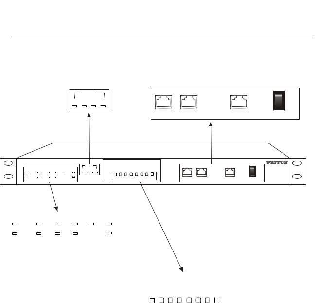
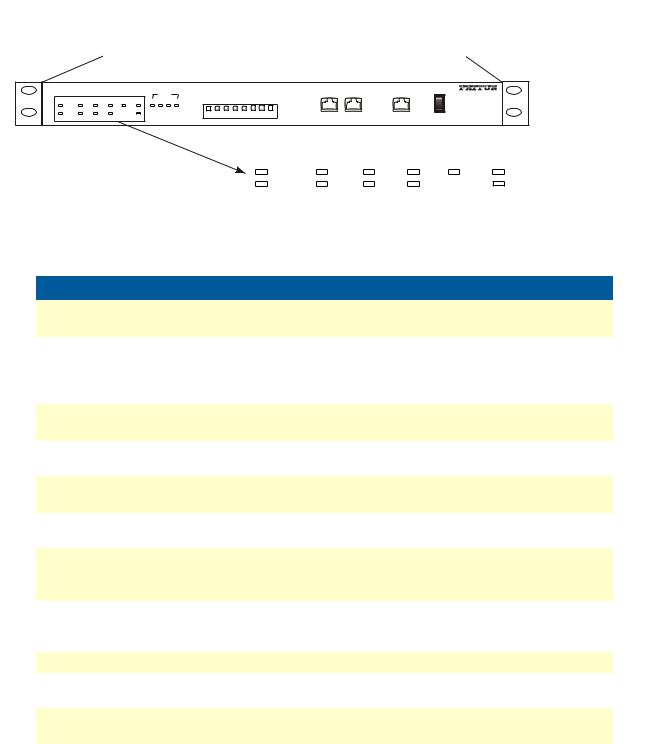
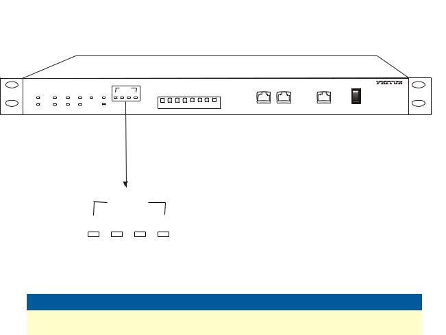
Front View
TRIBUTARY STATUS Indicator LED’s |
Interfaces and Button |
|
||||
|
E1 LOS |
|
|
|
OFF |
|
1 |
2 |
3 |
4 |
|
|
O |
|
|
I ON |
||||
|
|
|
|
|
|
|
|
|
|
MANG |
ETH |
PHONE |
POWER |
|
|
|
|
|
|
|
PWR |
ALM |
WORKA |
NOPA |
LOF |
E-3 |
1 2 3 4 |
RCLVC |
MUTE |
MASK |
ENALS |
OP1LO |
OP2LO |
OP3LO |
OP4LO |
|
|
|
O |
Model 1195/4E1 Optical Multiplexer |
|
|
|
|
|
|
|
|
|
|
|
|
|
|
||||
|
|
|
|
|
|
E1 LOS |
|
|
|
|
|
|
|
|
|
|
|
OFF |
|
|
|
|
|
|
|
|
|
|
|
|
|
|
|
|
|
|
|
|
|
|
|
|
|
|
OFF |
|
|
|
|
|
|
|
|
|
|
I ON |
CV |
RPD |
WORKB |
NOPB |
|
E-6 |
|
ON 1 |
2 |
3 |
4 |
1 |
2 |
3 |
4 |
MANG |
ETH |
PHONE |
POWER |
PWR |
ALM |
WORKA |
NOPA |
LOF E-3 |
CV |
RPD |
WORKB |
NOPB |
E-6 |
|
|
|
|
|
Global Indicator LEDs
OFF |
CLR_CV |
TEMU |
ASKM |
EN_ALS |
LOOP1 |
2POO L |
LOOP3 |
OOP4 L |
|
1 |
2 |
3 |
4 |
1 |
2 |
3 |
4 |
|
|
ON |
|
||||||||
|
|
|
|
|
|
|
|
|
|
Display Select and Config Switches
Figure 2. 1195/4E1 front view
Front View |
15 |
Model 1195 Getting Started Guide |
1 • General information |
|
|
Model 1195/4E1 Optical Multiplexer |
RLC CV |
TEMU |
MASK |
NELS A |
1POO L |
OOP2 L |
3PO LO |
LOOP4 |
|
|
|
|
|||||
|
|
|
|
|
E1 LOS |
|
|
|
OFF |
||||||||
PWR |
ALM |
WORKA |
NOPA |
LOF E-3 |
1 2 3 4 |
|
|
|
|||||||||
|
|
|
O |
||||||||||||||
|
|
|
|
|
|
OFF |
|
|
|
|
|
|
|
|
|
|
I ON |
CV |
RPD |
WORKB |
NOPB |
E-6 |
|
ON 1 |
2 |
3 |
4 |
1 |
2 |
3 |
4 |
MANG |
ETH |
PHONE |
POWER |
|
|
|
PWR |
ALM |
WORKA |
NOPA |
LOF |
E-3 |
|
|
|
|
CV |
RPD |
WORKB |
NOPB |
|
E-6 |
|
|
|
|
|
|
|
|
|
||
|
Figure 3. Front LEDs |
|
|
|
|
|
|||
|
|
|
|
|
|
|
|
|
|
Name |
Color |
|
|
|
|
Function |
|
|
|
|
|
|
|
|
|
|
|
||
PWR |
Green |
ON – Unit is powered |
|
|
|
|
|||
|
|
OFF – Unit is off |
|
|
|
|
|
||
|
|
|
|
|
|
|
|
||
ALM |
Red |
ON – Local alarm detected |
|
|
|
|
|||
|
|
Blinking – Remote alarm detected |
|
|
|
||||
|
|
OFF – No alarm currently detected |
|
|
|
||||
|
|
The local alarms take priority over remote alarms. |
|||||||
|
|
|
|
|
|
|
|
|
|
CV |
Yellow |
ON – CV alarm |
|
|
|
|
|
||
|
|
OFF – No CV alarm |
|
|
|
|
|||
|
|
|
|
|
|
|
|||
RPD |
Yellow |
ON – Remote power off detected |
|
|
|
||||
|
|
OFF – No RPD alarm |
|
|
|
|
|||
|
|
|
|
|
|||||
WORKA |
Green |
ON – Optical A is working. Optical B indication is off. |
|||||||
|
|
OFF – Optical A is not working. |
|
|
|
||||
|
|
|
|
|
|||||
WORKB |
Green |
ON – Optical B is working. Optical A indication is off. |
|||||||
|
|
OFF – Optical B is not working. |
|
|
|
||||
|
|
|
|
|
|||||
NOPA |
Red |
ON – Optical signal loss is detected on port A. |
|||||||
|
|
Blinking – ALS is enabled on the remote device. |
|||||||
|
|
OFF – No loss |
|
|
|
|
|
||
|
|
|
|
|
|||||
NOPB |
Red |
ON – Optical signal loss is detected on port B. |
|||||||
|
|
Blinking – ALS is enabled on the remote device. |
|||||||
|
|
OFF – No loss |
|
|
|
|
|
||
|
|
|
|
|
|
||||
LOF |
Red |
ON – Loss of frame detected at optical port |
|
|
|||||
|
|
|
|
|
|||||
E-3 |
Red |
ON – Line bit error rate is over 10-6 detected at optical port |
|||||||
|
|
OFF – No loss |
|
|
|
|
|
||
|
|
|
|
|
|||||
E-6 |
Yellow |
ON – Line bit error rate is over 10-6 detected at optical port |
|||||||
|
|
OFF – No loss |
|
|
|
|
|
||
|
|
|
|
|
|
|
|
|
|
Front View |
16 |
Model 1195 Getting Started Guide |
1 • General information |
|
|
Model 1195/4E1 Optical Multiplexer |
|
|
RCLCV |
MUTE |
MASK |
NELSA |
1PLOO |
2OPLO |
3PLOO |
4PLOO |
|
|
|
|
|||
PWR |
ALM |
WORKA |
NOPA LOF |
E-3 |
1 2 3 4 |
|
|
|
O |
||||||||
|
|
|
|
|
E1 LOS |
|
|
|
|
|
|
|
|
|
|
|
OFF |
|
|
|
|
|
|
|
|
|
|
|
|
|
|
|
|
|
|
|
|
|
|
|
|
OFF |
|
|
|
|
|
|
|
|
|
|
I ON |
CV |
RPD |
WORKB |
NOPB |
E-6 |
|
ON 1 |
2 |
3 |
4 |
1 |
2 |
3 |
4 |
MANG |
ETH |
PHONE |
POWER |
|
|
|
E1 LOS |
|
|
|
|
1 |
2 |
3 |
4 |
|
|
|
|
|
|
|
||
|
|
|
Figure 4. Tributary Status LEDs |
|||
|
|
|
|
|
|
|
Name |
|
Color |
|
|
Function |
|
|
|
|
|
|
|
|
E1-LOS |
|
Red |
|
ON – E1 signal loss happened at the corresponding tributary |
||
|
|
|
|
|
OFF – No loss |
|
|
|
|
|
|
|
|
Front View |
17 |
Model 1195 Getting Started Guide |
1 • General information |
|
|
PWR |
ALM |
WORKA |
NOPA |
LOF |
E-3 |
1 2 3 4 |
CLRCV |
EMUT |
ASKM |
ENALS |
1POLO |
2POOL |
3POOL |
4POOL |
|
|
|
O |
Model 1195/4E1 Optical Multiplexer |
|
|
|
|
|
|
|
|
|
|
|
|
|
|||||
|
|
|
|
|
|
E1 LOS |
|
|
|
|
|
|
|
|
|
|
|
OFF |
|
|
|
|
|
|
|
|
|
|
|
|
|
|
|
|
|
|
|
|
|
|
|
|
|
|
OFF |
|
|
|
|
|
|
|
|
|
|
I ON |
CV |
RPD |
WORKB |
NOPB |
|
E-6 |
|
ON 1 |
2 |
3 |
4 |
1 |
2 |
3 |
4 |
MANG |
ETH |
PHONE |
POWER |
OFF |
LRC_ VC |
ETMU |
SKMA |
EN_LS A |
1PO LO |
LOOP2 |
3PLOO |
LOOP4 |
|
1 |
2 |
3 |
4 |
1 |
2 |
3 |
4 |
|
|
ON |
|
||||||||
|
|
|
|
|
|
|
|
|
|
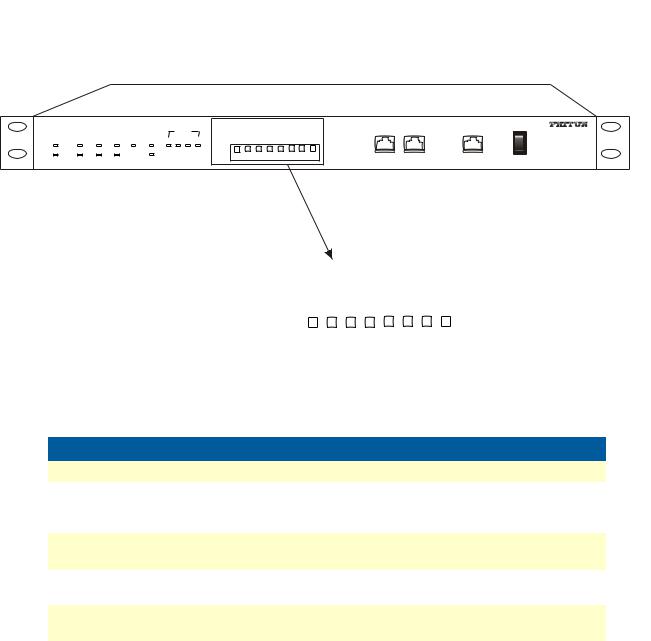
Figure 5. Config Switch LEDs
Name |
Function |
|
|
CV-CLR |
ON – Clear CV alarm |
|
|
MUTE |
ON – Alarm sound is muted. Speaker will sound if any alarms have occurred. |
|
OFF – Speaker will not sound if there are alarms. Note that the ringing of the |
|
order wire cannot be muted. |
|
|
MASK |
ON – All current E1 loss alarms will be masked. In addition, alarms will be trig- |
|
gered if a new event of E1 signal loss occurs, even if MASK is ON. |
|
|
ALS_EN |
ON – Enable ALS function |
|
OFF – Disable ALS function |
|
|
LOOP 1-4 |
ON – Enable remote loopback of E1 |
|
OFF – Disable remote loopback of E1 |
Front View |
18 |
Model 1195 Getting Started Guide |
1 • General information |
|
|
PWR |
ALM |
WORKA |
NOPA |
LOF |
E-3 |
1 2 3 4 |
CLRCV |
EMUT |
ASKM |
ENALS |
1POLO |
2POOL |
3POOL |
4POOL |
|
|
|
O |
Model 1195/4E1 Optical Multiplexer |
|
|
|
|
|
|
|
|
|
|
|
|
|
|||||
|
|
|
|
|
|
E1 LOS |
|
|
|
|
|
|
|
|
|
|
|
OFF |
|
|
|
|
|
|
|
|
|
|
|
|
|
|
|
|
|
|
|
|
|
|
|
|
|
|
OFF |
|
|
|
|
|
|
|
|
|
|
I ON |
CV |
RPD |
WORKB |
NOPB |
|
E-6 |
|
ON 1 |
2 |
3 |
4 |
1 |
2 |
3 |
4 |
MANG |
ETH |
PHONE |
POWER |
|
|
|
OFF |
|
|
|
O |
|
|
|
I ON |
MANG |
ETH |
PHONE |
POWER |
|
|
|
|
|
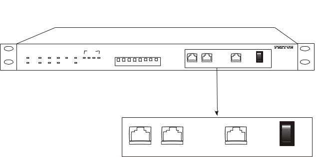
Figure 6. Interfaces |
|
|
|
S.No. |
Name |
Description |
|
|
|
1. |
MANG |
Ethernet Management Interface (RJ-45) |
|
|
Cable: CAT-5 crossover or straight through |
|
|
Note: In default Telnet |
|
|
User Name : superuser (case sensitive) |
|
|
Password: superuser (case sensitive) |
2. |
ETH |
Ethernet Interface (RJ-45) |
|
|
Cable: CAT-5 crossover or straight through |
|
|
|
3. |
PHONE |
Phone Interface (RJ-11) |
|
|
Cable: Standard 2-wire cable (64 Kbps, PCM coding) |
4. |
POWER |
Power Switch |
|
|
ON – Power ON |
|
|
OFF – Power OFF |
|
|
|
Front View |
19 |

Model 1195 Getting Started Guide |
1 • General information |
|
|
Rear View
Figure 7. 1195/4E1 rear view
Optical Interfaces |
Console and Earth point |
OPTICAL B |
OPTICAL A |
CONSOLE |
|||
TX |
RX |
TX |
RX |
||
|
|||||
|
|
|
|
RS232 |
|
DC 48 V |
|
|
|
|
|
~ 220 V |
OPTICAL B |
OPTICAL A |
|
|
|
|
E1 4-1 |
CONSOLE |
|||
PGND GND -48V |
TX RX |
TX RX |
|||
|
|
||||
|
|
|
II |
RS232 |
|
|
|
|
|
||
~ 220 V
PGND GND -48V
E1 4-1 |
Power |
E1 Interfaces |
Rear View |
20 |
Chapter 2 Applications overview
Chapter contents
Typical Model 1195 Application.................................................................................................................. |
22 |
21
Model 1195 Getting Started Guide |
2 • Applications overview |
|
|
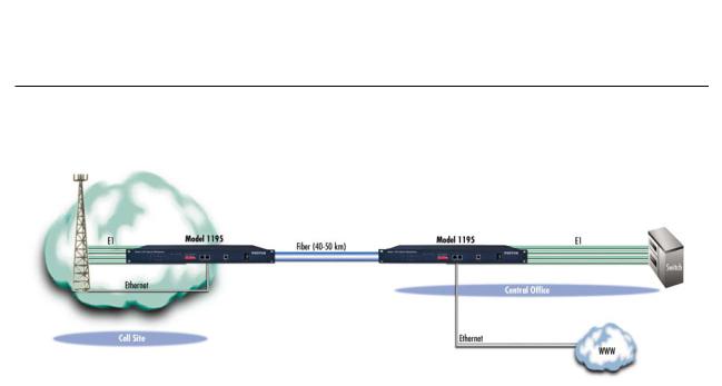
Typical Model 1195 Application
Figure 8 shows the typical application for the 1195 model.
Figure 8. Typical application for Model 1195
Typical Model 1195 Application |
22 |

Chapter 3 Model 1195/4E1 installation |
|
Chapter contents |
|
Connecting power ................................................................................................................................................. |
24 |
AC Power ....................................................................................................................................................... |
24 |
DC Power ....................................................................................................................................................... |
24 |
Grounding ...................................................................................................................................................... |
25 |
Connecting the optical interface ............................................................................................................................ |
26 |
Connecting the DB-37 connector.......................................................................................................................... |
27 |
Connecting E1 links .............................................................................................................................................. |
28 |
Definition for E1 Interfaces ............................................................................................................................ |
28 |
Connecting Ethernet Links.................................................................................................................................... |
28 |
Verifying the connection ................................................................................................................................. |
28 |
Definition for Ethernet Interfaces ................................................................................................................... |
28 |
23
Loading...