

Page 1
USER
MANUAL
MODEL 2120
RS-232 Single Port
Terminal Server
An ISO-9001
Certified Company
Part# 07M2120-UM
Doc# 08302U2-001,
Rev. D
Revised 10/27/06
SALES OFFICE
(301) 975-1000
TECHNICAL SUPPORT
(301) 975-1007
Page 2

TABLE OF CONTENTS
1.0 Warranty Information ................................................................. 5
1.1 FCC Information ........................................................................... 5
1.2 CE Notice...................................................................................... 6
1.3 Service.......................................................................................... 6
2.0 General Information.................................................................... 7
2.1 Product Features.......................................................................... 7
2.2 Software Features ........................................................................ 7
RS-232 Serial Interface................................................................ 7
PPP/SLIP...................................................................................... 8
IP Forwarding/NAT....................................................................... 9
Raw TCP/TELNET ....................................................................... 9
System Features ........................................................................ 10
User Database............................................................................ 10
Utilities........................................................................................ 10
View (Show) Features................................................................ 11
2.3 Description.................................................................................. 12
3.0 Configuration ............................................................................ 15
3.1 Configuration Switches............................................................... 15
Default Settings.......................................................................... 16
Detailed Switch Settings............................................................. 16
3.2 Software Configuration............................................................... 16
Model 2120 Software Command System................................... 17
Model 2120 Help Menu/Command Hierarchy ............................ 17
Entering Commands................................................................... 19
Activating Configuration Commands.......................................... 19
3.3 Default Configuration Parameters .............................................. 20
EIA232 Interface Defaults........................................................... 20
PPP Defaults.............................................................................. 20
RawTCP/Telnet Defaults............................................................ 20
System Defaults ......................................................................... 21
User Database Defaults ............................................................. 21
3.4 Initial Unit Configuration.............................................................. 21
3.5 Remote Configuration of the Unit ............................................... 25
3.6 Sample 2120 Configurations ...................................................... 26
Telnet/TCP Operation................................................................. 26
RawTCP Operation .................................................................... 29
PPP Operation............................................................................ 32
SLIP Operation........................................................................... 35
3.7 User Database............................................................................ 38
User Name ................................................................................. 38
Password.................................................................................... 38
Privilege...................................................................................... 39
Creating Users............................................................................ 39
Deleting All Users....................................................................... 40
Deleting A Single User ............................................................... 40
2
Page 3

Modifying A User........................................................................ 41
3.8 IP Addressing ............................................................................. 42
Unit IP Address........................................................................... 42
Serial Interface IP Address......................................................... 42
Subnet Mask............................................................................... 44
3.9 Name Servers............................................................................. 44
Domain Name Server (DNS)...................................................... 44
Windows Name Server (WINS).................................................. 45
Obtaining Name Server Addresses From PPP Client................ 45
Obtaining Name Server Addresses From SLIP Client................ 45
3.10 Software Installation Instructions................................................ 46
Software Installation Procedures Using Your Own
FTP Server................................................................................. 46
Software Installation Procedures Using Patton’s
FTP Server................................................................................. 47
4.0 Installation................................................................................. 49
4.1 Model 2120 Connection.............................................................. 49
4.2 AC Power Connection ................................................................ 49
AC Power Supply (100-240VAC) ............................................... 50
DC Power Supply (36-60VDC)................................................... 50
5.0 Operation................................................................................... 51
5.1 LED Status Indicators................................................................. 51
Rear Panel LEDs........................................................................ 51
Top Panel LEDs ......................................................................... 52
5.2 Flow Control And Session Control.............................................. 53
Flow Control ............................................................................... 53
Session Control.......................................................................... 54
5.3 Using "Show" Commands For 2120 Status................................ 54
5.4 2120 Utilities............................................................................... 54
Boot............................................................................................ 54
EIA232 Connection Closure....................................................... 55
Ping ............................................................................................ 55
Raw-TCP.................................................................................... 56
Telnet.......................................................................................... 56
Display ARP Table ..................................................................... 56
A Model 2120 Single Port Terminal Server Specifications....... 57
A.1 Serial Interface ............................................................................ 57
A.2 Serial Transmission .................................................................... 57
A.3 DCE/DTE .................................................................................... 57
A.4 RS-232 Status Indicators ............................................................ 57
A.5 Ethernet Interface ....................................................................... 57
A.6 Ethernet Standard ....................................................................... 57
A.7 System Status Indicators ............................................................ 57
A.8 Protocols Supported ................................................................... 57
A.9 Management Services ................................................................ 57
A.10 Memory ....................................................................................... 57
3
Page 4

A.11 Power Supply Options ................................................................ 57
A.12 Temperature ............................................................................... 58
A.13 Altitude ........................................................................................ 58
A.14 Humidity ...................................................................................... 58
A.15 Dimensions ................................................................................. 58
A.16 Weight ......................................................................................... 58
B Model 2120 Single Port Terminal Server
Software Command Definitions .............................................. 59
B.1 Activate Image Commands ......................................................... 59
B.2 Boot Commands ......................................................................... 59
B.3 Configure Commands ................................................................. 59
B.4 EIAONCLOSE Commands ......................................................... 69
B.5 FTP Commands .......................................................................... 69
B.6 Ping Commands ......................................................................... 70
B.7 RAWTCP Commands ................................................................. 70
B.8 SHOW Commands ..................................................................... 70
C Pin Configurations.................................................................... 81
4
Page 5

1.0 WARRANTY INFORMATION
Patton Electronics
defects, and will—at our option—repair or replace the product should it
fail within one year from the first date of shipment.
This warranty is limited to defects in workmanship or materials, and does
not cover customer damage, abuse or unauthorized modification. If this
product fails or does not perform as warranted, your sole recourse shall
be repair or replacement as described above. Under no condition shall
Patton Electronics
product. These damages include, but are not limited to , the f ollo wing: lost
profits, lost savings and incidental or consequential damages arising
from the use of or inability to use this product.
cifically disclaims all other warranties, expressed or implied, and the
installation or use of this product shall be deemed an acceptance of
these terms by the user.
1.1 FCC INFORMATION
This equipment has been tested and found to comply with the limits for a
Class A digital device, pursuant to P art 15 of the FCC Rules. These limits
are designed to provide reasonable protection against harmful interference when the equipment is operated in a commercial environment. This
equipment generates, uses, and can radiate radio frequency energy and,
if not installed and used in accordance with the instruction manual, may
cause harmful interference to radio communications. Operation of this
equipment in a residential area is likely to cause harmful interference in
which case the user will be required to correct the interference at his own
expense. If this equipment does cause harmful interference to radio or
television reception, which can be determined by turning the equipment
off and on, the user is encouraged to try to correct the interference by
one or more of the following measures:
warrants all Model 2120 components to be free from
be liable for any damages incurred b y the use of this
Patton Electronics
spe-
• Reorient or relocate the receiving antenna
• Increase the separation between the equipment and receiver
• Connect the equipment into an outlet on a circuit different from that to
which the receiver is connected
5
Page 6

1.2 CE NOTICE
The CE symbol on your Patton Electronics equipment indicates that it is
in compliance with the Electromagnetic Compatibility (EMC) directive
and the Low Voltage Directive (LVD) of the European Union (EU). A Certificate of Compliance is available by contacting Technical Support.
Note
THIS DEVICE IS NOT INTENDED TO BE CONNECTED TO
THE PUBLIC NETWORK.
1.3 SERVICE
All warranty and nonwarranty repairs must be returned freight prepaid
and insured to Patton Electronics. All returns must have a Return Materials Authorization number on the outside of the shipping container. This
number may be obtained from Patton Electronics Technical Services at:
Tel:
(301) 975-1007
E-mail:
URL:
support@patton.com
www.patton.com
Note
Packages received without an RMA number will not be
accepted.
Patton Electronics' technical staff is also available to answer any questions that might arise concerning the installation or use of your Patton
Model 2120. Technical Service hours:
through
Friday
.
8AM to 5PM EST, Monday
6
Page 7

2.0 GENERAL INFORMATION
Thank you for your purchase of this
product has been thoroughly tested and is warranted for One Year parts
and labor. If any questions or problems arise during installation or use of
this product, please do not hesitate to contact
nical Support
2.1 PRODUCT FEATURES
• Enables control of any RS-232 asynchronous serial device ov er a LAN
or via the Internet
• Asynchronous data rates up to 115.2 kbps
• DTE/DCE-selectable serial port
• RS-232 status indicators
• RS-232 serial connection via DB-25 male and female, DB-9 male and
female, and RJ-45 female connector options
• 802.3 10Base-T LAN connection via RJ-45 female connector
• Ethernet Link and System Status Indicators
• User-configurable session options
• Supports standard protocols including TCP, UDP, IP, ICMP, TELNET,
ARP, DHCP, FTP, SLIP, PPP, and PAP
at
(301) 975-1007
Patton Electronics
Patton Electronics Tech-
.
product. This
• Comes with 1 Mbyte RAM and 512 kbytes FLASH
• Small package attaches directly to terminal equipment
• AC or DC power options
• Software updates via Patton’s FTP site
• Can be used as single-port remote access server
2.2 SOFTWARE FEATURES
RS-232 Serial Interface
• Selectable asynchronous data rates from 50 bps to 115.2 kbps
• Selectable serial port options of DCE, DTE
• DCE/DTE on configuration reset (SW2)
7
Page 8

• Selectable RS-232 character length options of 5, 6, 7, 8
• Selectable RS-232 flow control options of none, hardware, xonxoff
• Selectable RS-232 parity options of none, odd, even, high
• Selectable RS-232 stop length options of 1, 2
• Selectable RS-232 interface protocol options of Telnet, Raw-TCP,
SLIP, and PPP
• Ability to display the current active user on the serial interface
• Ability to disable the user interface at the serial interface when using
Telnet or Raw-TCP
• Receive Buffer Length and Receive Idle Character Triggering support
• Selectable serial interface inactivity timeout (minutes) with
disable option
PPP/SLIP
• Enables devices connected to the serial interface with Ethernet con-
nectivity using either PPP or SLIP protocols
• Proxy ARP provides the de vice connected to the serial interface with a
virtual Ethernet connection
• DHCP enable/disable for static or dynamic IP addressing for PPP
operations
• Configurable DHCP PPP hardware address
• Optional IP addressing from the PPP client device connected to the
serial interface instead of using static or dynamic IP addressing
• Optional PAP user authentication protocol for PPP operations
• Supports Primary and Secondary Domain Name Server (DNS or
WINS) functionality
• Supports DNS address static configuration in the PPP client device
• Ability to configure either 16 or 32-bit FCS when using PPP (previously
fixed at 16)
• Ability to configure receive and transmit ACCM (Async-Control Char-
acter Map) when using PPP (previously fixed at 0xFFFFFFFF).
8
Page 9

• DHCP:
– DHCP enable/disable for static or dynamic IP addressing of the unit
– Permit the use of the DHCP offered IP address in the IP address
destination field
– DHCP Client support for Default Gateway
IP Forwarding/NAT
• Ability to forward IP packets from multiple Ethernet devices across its
serial interface in both SLIP and PPP mode
• NAT support for a single device connected on the Ethernet interface
when IP Forwarding is enabled
• FTP/Port command support when NAT is enabled
• NAT algorithm conforms to RFC 1624
Raw TCP/TELNET
• Permits automatic connection request to a remote device
• Permits incoming connection requests from remote devices on the
serial interface
• Selectable frequency (in seconds) of the automatic connection
requests to remote device
• Selectable TCP port number for serial interface
• Selectable destination IP address for sending automatic connection
requests to a remote device
• Selectable TCP port number for sending automatic connection
requests to a remote device
• Optional User ID & Password capability when sending automatic con-
nection requests to remote device
• Selectable serial interface session termination character
• Flexible Telnet session NVT configuration
• Serial Port TCP Inactivity Support
• Ability to specify TCP port number for the user interface
9
Page 10

System Features
• Ability to display boot message on the serial interface
• Selectable default gatew ay IP address for use when the destination IP
address cannot be found
• DHCP enable/disable for static or dynamic IP addressing of the unit
• Selectable unit IP address
• Ability to change factory assigned unit MAC Address, MAC Address
preserved when configuration is default
• Ability to enable/disable unit management/configuration via remote
Telnet session
• Ability to display the current active user on the serial interface
• Ability to disable the user interface at the serial interface when using
Telnet or Raw-TCP
• Selectable unit management inactivity timeout (minutes) with disable
option
• Ability to change the preset system command prompt (TS>) to
uniquely identify the unit
• Selectable unit Subnet Mask
• RAW UDP protocol support
User Database
• Fully integrated 64-user database with Telnet, RawTCP and PPP oper-
ation
• All user security accessed through database
• Telnet and RawTCP operations support multiple users
Utilities
• Ability to remotely perform a soft boot of the unit
• Configuration reset to factory default configuration via SW1 (Will not
reset MAC Address)
• Ability to clear configuration changes prior to being activated/written to
memory
10
Page 11

• Ability to reset non-volatile configuration parameters
• Ability to remotely close the serial interface connection
• Ability to FTP to a remote device
• Ability to Ping to a remote device
• Ability to Raw-TCP to a remote device
• Ability to Telnet to a remote device
• Ability to download software using FTP and write/activate to flash
memory
• Ability to display ARP Table
View (Show) Features
• Ability to view all current serial interface related parameters
• Ability to view current setting of each individual serial interface related
parameter
• Ability to view all current Raw-TCP related parameters
• Ability to view current setting of each individual Raw-TCP related
parameters
• Ability to view all current system related parameters
• Ability to view current setting of each individual system related
parameters
• Ability to view TCP connection state
• Ability to view DHCP state, passed lease time (seconds), renew lease
time (seconds), rebind lease time (seconds), and expire lease time
(seconds)
• Ability to view current software version
• Ability to view all current PPP/SLIP related parameters
• Ability to view current setting of each individual PPP/SLIP related
parameter
11
Page 12
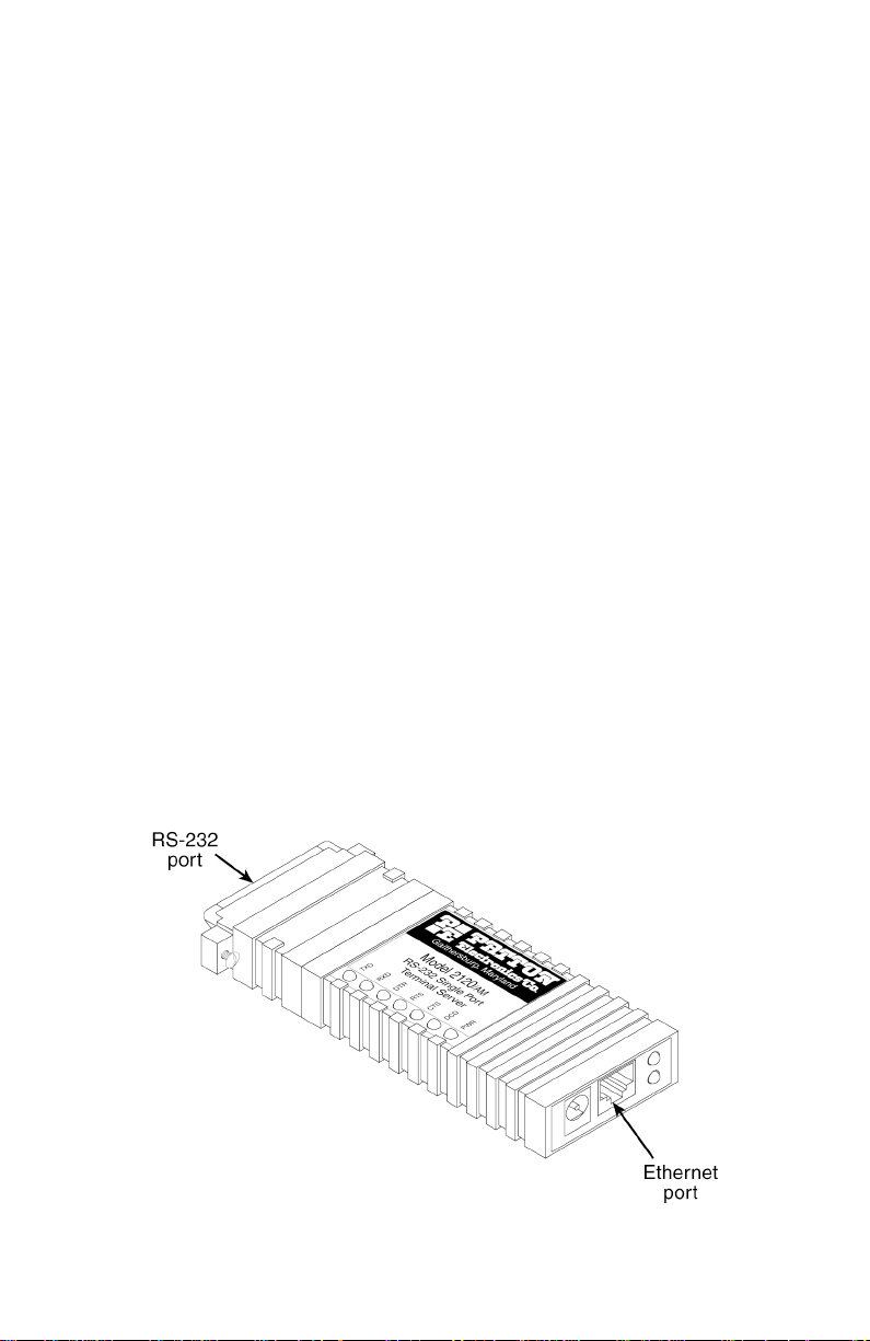
2.3 DESCRIPTION
The Model 2120 Single Port Terminal Server (see Figure 1) provides a
quick, easy to use solution for connecting traditional RS-232 terminals
and devices to the Local Ethernet/IP Network. The Model 2120 can also
function as a very cost effective single port remote access server. Serial
asynchronous device connectivity across the LAN is provided using Telnet/TCP, Raw-TCP, SLIP, or PPP protocols. The v ersatile and feature-rich
Model 2120 can literally be used in thousands of different applications
and environments, including:
• Factory floor machinery
• Security systems
• Printers
• Scales
• Barcode scanners
• Various instruments
• Climate control systems
• ASCII terminals
• Vending machines
• Cash registers and other point-of-sale (POS) devices
• RS-232 control/console ports (PBX, switches, etc.)
Figure 1.
Model 2120 showing location of Ethernet and RS-232 ports.
12
Page 13

The Model 2120 is initially configured via the serial interface using a
dumb terminal or terminal emulation software in VT-100 mode. The serial
interface factory default asynchronous setting is 9600 bits/second, 8 bits
per character, no parity, and 1 stop bit. All configuration parameters can
be set via the serial interface using the 2120's menu-driven command
system. Once initial configuration is complete with a static or dynamically assigned IP address and the 2120 is connected to the LAN, configuration parameters can be modified, configuration parameters and
operational status can be viewed, and utilities can be performed ov er the
LAN using a Telnet session.
The Model 2120 can use DHCP (Dynamic Host Configuration Protocol)
to dynamically obtain the unit IP address over the LAN from a DHCP
server. The 2120 sends the DHCP server MAC address information and
dynamically obtains its IP address based on the unit MAC address. This
feature reduces the numbers of IP addresses on the network and minimizes network administration.
Telnet/TCP operation provides an asynchronous device connected to the
Model 2120 serial interface with connectivity to a remote device/application over the LAN. Asynchronous data received at the Model 2120 serial
interface is sent to the remote device using the Telnet/TCP protocol.
Asynchronous data received from the Telnet/TCP connection is sent to
the device connected to the Model 2120 serial interface. When the
remote device accessed over the LAN performs the same type of operation, an asynchronous connection is formed between the two devices.
Raw-TCP operation is identical to Telnet/TCP operation with one exception. The data passed between the 2120's serial interface and the
remote device/application is directly passed using TCP (Telnet is not
used). Aside from this one e xception, Ra w-TCP contains all the f eatures
and functionality as Telnet/TCP.
PPP operation provides an asynchronous device connected to the Model
2120 serial interface with LAN connectivity. The Model 2120 and the
device connected to its serial interface e xchange IP pac kets where each
IP packet is PPP encapsulated. The Model 2120 uses proxy ARP to provide the device connected to the serial interface with a virtual LAN connection. The Model 2120 optionally provides PAP as a user
authentication protocol. PAP security can be used to validate a user trying to establish a LAN connection from the device connected to the
Model 2120 serial interface. The Model 2120 IP address for PPP operations can be either configured statically or dynamically using a DHCP
server. Further, the PPP IP address may be obtained from the PPP client device connected to the serial interface.
13
Page 14

SLIP operation provides a device connected to the Model 2120 serial
interface with LAN connectivity. The Model 2120 and the device connected to the serial interface exchange IP pack ets where each IP packet
is SLIP encapsulated. The Model 2120 uses proxy ARP to provide the
device connected to the serial interface with a virtual Ethernet connection. The Model 2120 serial interface IP address must be configured with
the same static IP address as the device connected to the serial interface.
When operating in PPP mode and accessing the Internet through the
Model 2120, the unit can be configured for DNS and/or WINS . These are
client name server options for Internet domain name resolution. When
operating in SLIP mode, the Model 2120 must be configured to obtain
the name server addresses from the SLIP client device.
The Model 2120 features a flexible user database with security for up to
64 users. This enables security access to the Model 2120 serial interface and administrative management of the Model 2120 over the LAN.
Each user is assigned a user name, password and privilege for accessing the serial interface (User), administration management features
(Admin), or both. If the Model 2120 is configured for PPP (and PAP
security is enabled), the user may connect from a remote PPP client
through a modem connected to the serial port of the Model 2120 and
receive / transmit data over the LAN.
The Model 2120 uses an integrated FTP (File Transfer Protocol) client to
obtain new program images and communicate with an FTP server. The
FTP client logs onto the FTP server and then can browse and display
files located on the FTP server. The FTP client can also obtain a new
program image (software release) from the FTP server. The program
image is first obtained from the FTP server across the LAN and then
stored in FLASH memory. This enables the Model 2120 to obtain new
functionality both easily and quickly. The latest Model 2120 software
release is available for download via upgrades.patton.com.
The Model 2120 features integrated utility f eatures to perform a variety of
functions. These include utilities to activate new software images (activateimage), remotely boot the Model 2120 over the LAN (boot), remotely
close the connection to the Model 2120 serial interface (eiaonclose), test
connectivity with another IP device (ping), establish a Telnet session with
another IP device with Telnet/TCP support (telnet), establish a Raw-TCP
session with another IP device with TCP support (rawtcp), and display
the Model 2120 ARP Table (za).
Last, the Model 2120 features the ability to view any or all configuration
parameter settings and operational status of the Model 2120 unit.
14
Page 15
3.0 CONFIGURATION
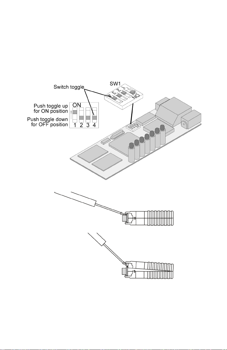
3.1 CONFIGURATION SWITCHES
SW1 is a set of four internal DIP switches (see Figure 2) that are used for
configuration reset purposes only . To access switch set SW1, use a small
flat blade screwdriver to open the Model 2120’s case as shown in
Figure 3.
Figure 2.
Figure 3.
Switch set SW1 location
Opening the Model 2120 case
To configure the DIP switches, use a small screwdriver and gently push
each switch to its proper setting. The ON and OFF positions are shown in
Figure 2.
15
Page 16

Default Settings
Default settings for the DIP switches are as follows:
Table 1:
Default Settings
Position Function Factory Default
SW1 Configuration Reset OFF
SW2 DCE/DTE on Config Reset OFF
SW3 Not Used (Must Be OFF) OFF
SW4 Not Used (Must Be OFF) OFF
Detailed Switch Settings
This section provides detailed information about the function of each DIP
switch and lists all possible settings.
• Switch 1: Configuration Reset. Set this switch to the ON position and
power cycle the unit to reset to the factory default configuration par ameters.
Note
This will not change the factory assigned NIC/MAC address.
• Switch 2: DCE/DTE on Configuration Reset. When a configuration
reset is being performed via Switch 1 (above), set this s witch to the ON
position to force the serial interface to DTE or to the OFF position to
force the serial interface to DCE.
Note
This switch is ONLY read when the configuration is reset
through Switch 1 (above).
• Switch 3: Not Used. This switch is not used and must remain in the
OFF position.
• Switch 4: Not Used. This switch is not used and must remain in the
OFF position.
3.2 SOFTWARE CONFIGURATION
The Model 2120 features a menu-driven command system that enables
the configuration of the 2120 software via the serial interface using a VT100 terminal or emulation session or over the LAN using a Telnet session. Since the Model 2120 is not pre-configured with an IP address for
your network, initial configuration of the Model 2120 is performed via the
serial interface (See “Initial Unit Configuration” on page 21.). Once initial
configuration is complete with a static or dynamically assigned IP
address and the Model 2120 is connected to the LAN, configuration
parameters can be modified over the LAN using a Telnet session. The
16
Page 17

management enable command is factory set to yes, which allows the
remote configuration of the Model 2120 over the LAN.
Model 2120 Software Command System
The Model 2120 Software Command System is designed with a series of
help menus and commands derived from the actual function descriptions. Once a session has been established with the 2120 and the system prompt (
displayed by pressing the <
*** Help Menu ***
activateimage - Activate Image Acquired With FTP Get
boot - Boot System
configure - Configure Parameters
eiaconclose - EIA232 Connection Close
ftp - FTP To Remote Device
ping - Ping Remote Device
rawtcp - Raw-TCP To Remote Device
show - Show Parameters and Statistics
telnet - Telnet To Remote Device
TS>
) appears, the main help menu (see Figure 4) will be
Enter
> key.
Figure 4.
Main Help Menu
The "configure" and "show" commands are used to access system,
eia232 and user database related parameters. Commands other than
"configure" and "show" result in ex ecuting an operation or utility and thus
do not have menus associated with them.
Model 2120 Help Menu/Command Hierarchy
The help menu/command hierarchy is shown in Figure 5 on page 18.
Note
For a detailed definition of all Model 2120 system commands,
valid entries, and defaults see Appendix B on page 59.
17
Page 18
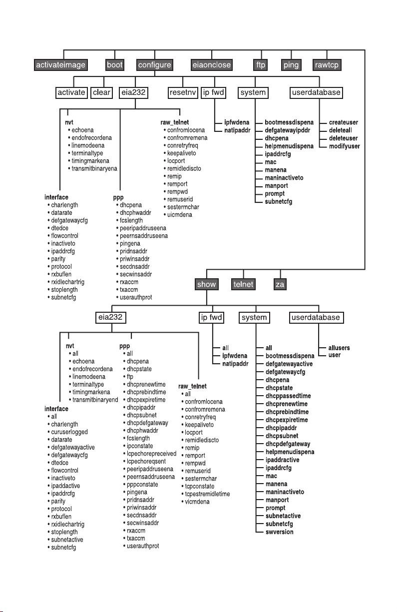
Figure 5.
Model 2120 Help Menu/Command Hierarchy
18
Page 19

Entering Commands
Commands are executed b y typing the appropriate command or commands at the system prompt (TS>) followed b y a valid entry (if applicable)
and the
<Enter>
key. If entering multiple commands, they must be entered
in hierarchy order (See “Model 2120 Help Menu/Command Hierarchy” on
page 17) and separated by a space. For example, the following command
string is entered to set the serial interface data rate to 115.2 kbps:
TS>configure eia232 interface datarate 115200<Enter>
For a single entry command such as “boot”, the following command is
entered to remotely boot the Model 2120:
TS>boot<Enter>
Commands entered are matched against the commands available for
that menu. Commands are accepted when the characters entered for a
command can only match one command for that menu. Thus shortcuts
are permitted when entering commands. The following examples show
how shortcut commands can be used to enter the same configure and
boot commands as listed above:
TS>c e i da 115200<Enter>
TS>b<Enter>
Activating Configuration Commands
The Model 2120 configuration parameters can be changed by using the
“configure” command and associated sub-commands. Immediately after
the necessary “configure” command string is entered, the “configure activate” command
write them to flash memory
must
be entered in order to activate the changes and
. For example, the command string used to
set the serial interface data rate to 115.2 kbps (see section “Entering
Commands”) must be immediately followed by the following command:
TS>configure eia232 interface datarate 115200<Enter>
TS>configure activate<Enter>
If successfully activated, the message “Activate is complete!” will display.
Note
The “configure activate” command MUST be entered after each
configuration change!
19
Page 20

3.3 DEFAULT CONFIGURATION PARAMETERS
The Model 2120 software is pre-configured with the following factory
default settings.
EIA232 Interface Defaults
• Character Length: 8 (bits)
• Datarate:
• DTE/DCE Physical Port:
• Flow Control:
• Inactive Timeout: 15 (minutes)
• Serial Interface IP Address:
• Parity:
• Serial Interface Protocol:
• Stop Length: 1 (bits)
• Serial Interface Subnet Mask:
PPP Defaults
• PPP DHCP Enable:
• Peer IP Address Use Enable:
• Peer Name Server Address Use Enable:
• Primary DNS Address:
• Primary WINS Address:
9600
none
(bits per second)
DCE
none
5.5.5.5
Telnet
255.255.255.0
no
no
0.0.0.0
0.0.0.0
no
• Secondary DNS Address:
• Secondary WINS Address:
• User Authentication Protocol:
RawTCP/Telnet Defaults
• Connection From Local Enable:
• Connection From Remote Enable: yes
0.0.0.0
0.0.0.0
none
no
20
Page 21

• Connection Retry Frequency: 0 (seconds)
• Local Port: 404
• Remote IP Address: 1.1.1.8
• Remote Port: 23
• Remote Password: UNDEFINED (no entry)
• Remote User ID: UNDEFINED (no entry)
• Session T ermination Character: 0x04 (Control-D)
System Defaults
• Boot Message Display Enable: yes
• Default Gateway IP Address: 0.0.0.0 (disabled)
• Unit DHCP Enable: yes
• Unit IP Address: 5.5.5.5
• Unit MAC Address: (Factory Assigned MAC/NIC Address)
• Management Enable: yes
• Management Inactive Timeout: 15 (minutes)
• Prompt: TS>
• Unit Subnet Mask: 255.255.255.0
User Database Defaults
• user database empty!
Note To reset the Model 2120 software to factory default settings, set
internal dip switch #1 to the ON position and power cycle the
Model 2120 unit. Once powered on, set switch #1 back to the
OFF position. This will reset all settings, with the e xception of the
unit MAC address, to the above listed factory defaults.
3.4 INITIAL UNIT CONFIGURATION
Unless pre-configured with an IP address for your LAN (not standard),
the Model 2120 must be initially configured via the serial interface using
the menu-driven command system and required terminal equipment as
described below:
21
Page 22

1. Verify that the four internal DIP switches are set to the OFF position
(factory default).
2. Using ribbon cable or other similar cable, connect the serial RS-232
port of a VT-100 ASCII terminal or similar DTE with terminal emulation software to the RS-232 port of the Model 2120.
3. Power up the emulation device and configure its RS-232 port as
follows:
– 9600 Baud
– 8 data bits, 1 stop bit, no parity
– ANSI, VT100 emulation
4. Power up the Model 2120.
5. After the Model 2120 is powered on, the ASCII terminal or emulation
device should display the following message:
Model 2120 Terminal Server
Software Version ?.?.? (will display current version)
TS>
Note If you are unable to connect with the Model 2120 and you have
rechecked your terminal emulation settings, it is recommended
that a configuration reset (to factory defaults) be performed on
the Model 2120 by setting internal dip switch #1 to the ON position and power cycling the Model 2120. Once powered on, set
switch #1 back to the OFF position. If still unable to establish a
connection, please contact Patton Electronics Technical Support
at (301) 975-1007.
6. Press the <Enter> key to see the main help menu screen.
*** Help Menu ***
activateimage - Activate Image Acquired With FTP Get
boot - Boot System
configure - Configure Parameters
eiaconclose - EIA232 Connection Close
ftp - FTP To Remote Device
ping - Ping Remote Device
rawtcp - Raw-TCP To Remote Device
show - Show Parameters and Statistics
telnet - Telnet To Remote Device
TS>
22
Page 23

7. Before proceeding with the configuration of the Model 2120 for your
application, it is suggested that the following "show all" commands
be executed in order to view the current system, eia232, and user
database configuration parameters:
TS>show system all<Enter> (or "s s a<Enter>")
Boot Message Display Enable : yes
Default Gateway Active : 0.0.0.0
Default Gateway Configured : 0.0.0.0
DHCP Enable : yes
DHCP State : initialize
DHCP Passed Lease Time (sec) : 0
DHCP Renew Lease Time (sec) : 0
DHCP Rebind Lease Time (sec) : 0
DHCP Expire Lease Time (sec) : 0
DHCP IP Address : 0.0.0.0
DHCP Subnet Mask : 0.0.0.0
DHCP Default Gateway : 0.0.0.0
Help Menu Display Enable : yes
IP Address Active : 192.168.200.1
IP Address Configured : 192.168.200.1
MAC Address : 0x00A0BA000D95
Management Enable : yes
Management Inactive Timeout (min) : 15
Management Port : 23
Prompt : TS>
Subnet Mask Active : 255.255.255.0
Subnet Mask Configured : 255.255.255.0
Software Version : 4.0.19
TS>show eia232 interface all<Enter> (or "s e i a<Enter>)
Character Length : 8
Current User Logged : (UNDEFINED)
Datarate : 9600
Default Gateway Active : 0.0.0.0
Default Gateway Configured : 0.0.0.0
DTE / DCE Physical Port : dce
Flow Control : none
Inactive Timeout (min) : 15
IP Address Active : 192.168.200.1
IP Address Configured : 8.8.8.8
Parity : none
Protocol : telnet
Receive Buffer Length (num char) : 1
Receive Idle Char For Trig (num char) : 1
Stop Length : 1
Subnet Mask Active : 255.255.255.0
Subnet Mask Configured : 255.255.255.0
23
Page 24

TS>show eia232 ppp all<Enter> (or "s e p a<Enter>)
DHCP Enable : no
DHCP State : initialize
DHCP Passed Lease Time (sec) : 0
DHCP Renew Lease Time (sec) : 0
DHCP Rebind Lease Time (sec) : 0
DHCP Expire Lease Time (sec) : 0
DHCP IP Address : 0.0.0.0
DHCP Subnet Mask : 0.0.0.0
DHCP Default Gateway : 0.0.0.0
DHCP Hardware Address : 0x000000000000
FCS Length : 16
IP Connection State : closed
LCP Echo Reply Received : 0
LCP Echo Request Sent : 0
Peer IP Address Use Enable : no
Peer Name Server Address Use Enable : no
PPP Connection State : closed
Ping Enable : yes
Primary Domain Name Server Address : 0.0.0.0
Primary Windows Name Server Address : 0.0.0.0
Secondary Domain Name Server Address : 0.0.0.0
Secondary Windows Name Server Address : 0.0.0.0
Receive Async-Control Character Map : 0xFFFFFFFF
Transmit Async-Control Character Map : 0xFFFFFFFF
User Authentication Protocol : none
TS>show eia232 rawtcp_telnet all<Enter> (or "s e r
a<Enter>)
Connection From Local Enable : no
Connection From Remote Enable : yes
Connection Retry Frequency (sec) : 0
Keepalive Timeout (sec) : 0
Local Port : 404
Remote Idle Disconnect Timeout (sec) : 0
Remote IP Address : 1.1.1.8
Remote Port : 23
Remote Password : (UNDEFINED)
Remote User ID : (UNDEFINED)
Session Termination Character : 0x04
TCP Connection State : listen
TCP Established/Remote Idle Time (sec) : 0
User Interface Command Enable : yes
TS>show userdatabase all<Enter> (or "s u a<Enter>)
user database empty!
24
Page 25

8. You are now ready to configure the Model 2120 for your application.
Configuration parameters will vary based upon the requirements of
each application.
For a detailed definition of all 2120 system commands, valid entries, and
defaults see Appendix B on page 59.
Note Contact your Network Administrator if you have questions
regarding configuration parameters required for your application
and/or LAN.
3.5 REMOTE CONFIGURATION OF THE UNIT
Once you have performed the initial configuration and the Model 2120 is
connected to and communicating with a LAN, the configuration parameters can be changed remotely from anywhere on the LAN using an FTP
Client (i.e. Windows Command Mode) on a computer that can communicate over the LAN.
1. From the Windows “Run” prompt at your computer, type: command
and click OK.
2. At the DOS prompt, Telnet into the 2120 by typing:
telnet <
the IP address of the 2120>
and pressing <Enter>.
3. When connected to the 2120, the computer should display the following message:
Model 2120 Terminal Server - Telnet Session
Software Version ?.?.? (will display current version)
TS>
4. Press the “Enter” key to see the main help menu screen.
*** Help Menu ***
activateimage - Activate Image Acquired With FTP Get
boot - Boot System
configure - Configure Parameters
eiaconclose - EIA232 Connection Close
ftp - FTP To Remote Device
ping - Ping Remote Device
rawtcp - Raw-TCP To Remote Device
show - Show Parameters and Statistics
telnet - Telnet To Remote Device
TS>
5. Y ou are no w ready to change the configuration of the Model 2120 f or
your application.
25
Page 26

For a detailed definition of all 2120 system commands, valid entries, and
defaults see Appendix B on page 59.
Note Contact your Network Administrator if you have questions
regarding configuration parameters required for your application
and/or LAN.
3.6 SAMPLE 2120 CONFIGURATIONS
The Model 2120 features and functionality allow it to operate in thousands of different applications; however, this section is not intended to
cover all the possibilities. The configuration samples provided below will
describe some of the typical 2120 applications and the configuration settings required for proper operation and serve as a useful reference when
configuring the Model 2120 for your own application. This section will not
discuss in detail the serial devices connected to the Model 2120 and
related operating systems and/or applications. Actual configurations will
vary from application to application based on the requirements and configuration of the serial device and related operating systems and applications.
Telnet/TCP Operation
In the typical Telnet/TCP application (see Figure 6), the user has a need
to remotely connect to a serial device located on the LAN for administration, configuration, monitoring, troubleshooting, data collection, etc. To
enable the remote connection via Telnet session, the Model 2120 is usually assigned a static IP address. The user then launches a Telnet/TCP
session from their Computer specifying the IP Address of the Model
2120 and port number and remotely connecting to it over the LAN. Once
connected, the Telnet/TCP client converts the asynchronous data into
TCP packets and sends it over the LAN to the IP address of the Model
2120. When received, the Model 2120 converts the packets back to
asynchronous data and forwards the data to the de vice connected to the
serial interface. The serial device sends asynchronous data back to the
Model 2120 and the Model 2120 converts the data into TCP pac kets and
sends it over the LAN back to the originating Telnet/TCP client and is
converted to asynchronous data to complete the cycle. Once the
desired tasks are performed, the Telnet session is usually terminated.
26
Page 27

Figure 6. Telnet / TCP Operation
System Settings
Boot Message Display Enable: yes
Default Gateway IP Address: <IP Address of Default Gateway of 2120
LAN>
DHCP Enable: no
IP Address Configured: <IP Address Assigned by Network Admin>
MAC Address: <Factory Assigned>
Management Enable: yes (or preferred)
Management Inactive Timeout (min): 15 (or preferred)
Prompt: TS> (or preferred)
Subnet Mask Configured: <Subnet Mask of 2120 LAN>
27
Page 28

EIA232 Interface Settings
Character Length: 8 (or setting required by serial device)
Datarate: 9600 (or setting required by serial device)
DTE / DCE Physical Port: dce (or setting required by serial device)
Flow Control: none (or setting required by serial device)
Inactive Timeout (min): 15 (or preferred)
IP Address Configured: <Same as System IP Address>
Parity: none (or setting required by serial device)
Protocol: telnet
Stop Length: 1 (or setting required by serial device)
Subnet Mask Configured: <Same as System Subnet Mask>
EIA232 PPP Settings
DHCP Enable: no
Peer IP Address Use Enable: no
Peer Name Server Address Use Enable: no
Primary Domain Name Server Address: 0.0.0.0
Primary Windows Name Server Address: 0.0.0.0
Secondary Domain Name Server Address: 0.0.0.0
Secondary Windows Name Server Address: 0.0.0.0
User Authentication Protocol: none
EIA232 Raw-TCP/Telnet Settings
Connection From Local Enable: no
Connection From Remote Enable: yes
Connection Retry Frequency (sec): 0
Local Port: 404 (or required setting)
Remote IP Address: 1.1.1.8
28
Page 29

Remote Port: 23
Remote Password: (UNDEFINED)
Remote User ID: (UNDEFINED)
Session T ermination Character: 0x04 (or preferred)
User Database Settings
user database empty! (or add users and corresponding passwords and
privileges)
RawTCP Operation
In the typical RawTCP application (see Figure 7), the user has a need to
connect a network enabled software application to a remote serial device
over the LAN for standard operation of the device. To enable the software application to communicate with the remote serial device, the
Model 2120 is usually assigned a static IP Address and the IP Address is
configured within the software application. When the software application is launched, it sends data in TCP packets over the LAN to the IP
Address of the Model 2120. When received, the Model 2120 converts
the packets to asynchronous data and forwards the data to the device
connected to the serial interface. The serial device sends asynchronous
data back to the Model 2120 and the Model 2120 converts the data into
TCP packets and sends it over the LAN back to the originating location/
application to complete the cycle. In this type of application, the RawTCP connection between the software application and Model 2120 is
configured so that is does not timeout/disconnect.
Note Legacy software applications that are not network enabled will
require a Comm Port Redirector application to communicate
with the Model 2120 and the remote serial device over the LAN.
A Comm Port Redirector is used to map serial communication
ports to the IP address and port number of the 2120 connected
to the remote serial device. This application resides on the computer hosting the legacy software application and basically tricks
the legacy application into packetizing the asynchronous data
into TCP packets and sending the data over the LAN to the IP
Address of the remote 2120/device, thus creating a transparent
serial connection.
29
Page 30

Figure 7. Raw - TCP Operation
System Settings
Boot Message Display Enable: yes
Default Gateway IP Address: <IP Address of Default Gateway of 2120
LAN>
DHCP Enable: no
IP Address Configured: <IP Address Assigned by Network Admin>
MAC Address: <Factory Assigned>
Management Enable: yes (or preferred)
Management Inactive Timeout (min): 15 (or preferred)
Prompt: TS> (or preferred)
Subnet Mask Configured: <Subnet Mask of 2120 LAN>
30
Page 31

EIA232 Interface Settings
Character Length: 8 (or setting required by serial device)
Datarate: 9600 (or setting required by serial device)
DTE / DCE Physical Port: dce (or setting required by serial device)
Flow Control: none (or setting required by serial device)
Inactive Timeout (min): 0
IP Address Configured: <Same as System IP Address>
Parity: none (or setting required by serial device)
Protocol: rawtcp
Stop Length: 1 (or setting required by serial device)
Subnet Mask Configured: <Same as System Subnet Mask>
EIA232 PPP Settings
DHCP Enable: no
Peer IP Address Use Enable: no
Peer Name Server Address Use Enable: no
Primary Domain Name Server Address: 0.0.0.0
Primary Windows Name Server Address: 0.0.0.0
Secondary Domain Name Server Address: 0.0.0.0
Secondary Windows Name Server Address: 0.0.0.0
User Authentication Protocol: none
EIA232 Raw-TCP/Telnet Settings
Connection From Local Enable: yes
Connection From Remote Enable: yes
Connection Retry Frequency (sec): <Preferred connection retry set-
ting>
Local Port: 404 (or required setting)
31
Page 32

Remote IP Address: <IP Address of Software App. Host>
Remote Port: <TCP Port Number of Software App. Host>
Remote Password: UNDEFINED (or required setting)
Remote User ID: UNDEFINED (or required setting)
Session T ermination Character: 0x04 (or preferred)
User Database Settings
user database empty! (or add users and corresponding passwords and
privileges)
PPP Operation
In the typical PPP application (see Figure 8), the user has a need to
remotely connect to a LAN for general access to the LAN (e-mail, applications, etc.) or for access to the Internet. To make this connection, the
user typically uses a dial-up modem with standard POTS line and
launches a PPP application to connect with a dial-up (or ISDN) modem
connected to the LAN. Once the connection is made between the PPP
dial-up peer and the modem, the Model 2120 serial interface will typically
obtain its operating IP address from an active DHCP server on the LAN
and then establishes a connection with the LAN. Once connected to the
LAN, the user is typically prompted to enter a user name and password
through the enabling of PAP user authentication protocol. When the correct user name and password are entered, the user is permitted access
to the LAN for general or Internet access. The data from the PPP application and LAN is converted into PPP packets and the data is moved
back and forth through the established PPP connection and over the
LAN. For domain name resolution, the Model 2120 is typically configured for DNS with the addresses of a primary and secondary DNS. In
this type of application, the PPP connection is usually terminated once
the user is finished accessing the LAN/Internet.
32
Page 33

Figure 8. PPP Terminal Server
System Settings
Boot Message Display Enable: no
Default Gateway IP Address: <IP Address of Default Gateway of 2120
LAN>
DHCP Enable: no
IP Address Configured: <IP Address Assigned by Network Admin>
33
Page 34

MAC Address: <Factory Assigned>
Management Enable: yes (or preferred)
Management Inactive Timeout (min): 15 (or preferred)
Prompt: TS> (or preferred)
Subnet Mask Configured: <Subnet Mask of 2120 LAN>
EIA232 Interface Settings
Character Length: 8 (or setting required by modem)
Datarate: 115200 (or setting required by modem)
DTE / DCE Physical Port: dte (or setting required by modem)
Flow Control: none (or setting required by modem)
Inactive Timeout (min): 15 (or preferred)
IP Address Configured: 8.8.8.8 (default/active address obtained using
DHCP)
Parity: none (or setting required by modem)
Protocol: ppp
Stop Length: 1 (or setting required by serial device)
Subnet Mask Configured: 255.255.255.0 (default/active mask obtained
using DHCP)
EIA232 PPP Settings
DHCP Enable: yes
Peer IP Address Use Enable: no
Peer Name Server Address Use Enable: no
Primary Domain Name Server Address: <Address of primary DNS>
Primary Windows Name Server Address: <Address of secondary
DNS>
Secondary Domain Name Server Address: 0.0.0.0
Secondary Windows Name Server Address: 0.0.0.0
34
Page 35

User Authentication Protocol: pap
EIA232 Raw-TCP/Telnet Settings
Connection From Local Enable: no
Connection From Remote Enable: yes
Connection Retry Frequency (sec): 0
Local Port: 404 (or required setting)
Remote IP Address: 1.1.1.8
Remote Port: 23
Remote Password: (UNDEFINED)
Remote User ID: (UNDEFINED)
Session T ermination Character: 0x04 (or preferred)
User Database Settings
Should include user names, passwords, and privileges of all users and
administrators
SLIP Operation
In the typical SLIP application (see Figure 9), the user has a need to
remotely connect to a LAN for general access to the LAN (e-mail, applications, etc.) or for access to the Internet. To make this connection, the
user typically uses a dial-up modem with standard POTS line and
launches a SLIP application to connect with a dial-up (or ISDN) modem
connected to the LAN. Once the connection is made between the SLIP
and the modem, the Model 2120 will establish a connection with the LAN
using a static IP address assigned by the Network Administrator. Once
connected to the LAN, the user is permitted access to the LAN for general or Internet access (SLIP will require user name put in 2120 database if there is one). The data from the SLIP client application and LAN
is converted into SLIP packets and the data is moved back and forth
through the established SLIP connection and over the LAN. For domain
name resolution, the Model 2120 must obtain name server addresses
from the SLIP client device connected to the serial interface. In this type
35
Page 36

of application, the SLIP connection is usually terminated once the user is
finished accessing the LAN/Internet.
Figure 9. SLIP Terminal Server
System Settings
Boot Message Display Enable: no
Default Gateway IP Address: <IP Address of Default Gateway of 2120
LAN>
DHCP Enable: no
36
Page 37

IP Address Configured: <2120 Unit IP Address Assigned by Network
Admin>
MAC Address: <Factory Assigned>
Management Enable: yes (or preferred)
Management Inactive Timeout (min): 15 (or preferred)
Prompt: TS> (or preferred)
Subnet Mask Configured: <Subnet Mask of 2120 Unit LAN>
EIA232 Interface Settings
Character Length: 8 (or setting required by modem)
Datarate: 115200 (or setting required by modem)
DTE / DCE Physical Port: dte (or setting required by modem)
Flow Control: none (or setting required by modem)
Inactive Timeout (min): 15 (or preferred)
IP Address Configured: <Serial Interface IP Address Assigned By
Network Admin>
Parity: none (or setting required by modem)
Protocol: slip
Stop Length: 1 (or setting required by serial device)
Subnet Mask Configured: <Subnet Mask of Serial Interface LAN>
EIA232 PPP Settings
DHCP Enable: no
Peer IP Address Use Enable: no
Peer Name Server Address Use Enable: yes
Primary Domain Name Server Address: 0.0.0.0
Primary Windows Name Server Address: 0.0.0.0
Secondary Domain Name Server Address: 0.0.0.0
Secondary Windows Name Server Address: 0.0.0.0
37
Page 38

User Authentication Protocol: none
EIA232 Raw-TCP/Telnet Settings
Connection From Local Enable: no
Connection From Remote Enable: yes
Connection Retry Frequency (sec): 0
Local Port: 404 (or required setting)
Remote IP Address: 1.1.1.8
Remote Port: 23
Remote Password: (UNDEFINED)
Remote User ID: (UNDEFINED)
Session T ermination Character: 0x04 (or preferred)
User Database Settings
user database empty! (or add users and corresponding passwords and
privileges)
3.7 USER DATABASE
The Model 2120 features a flexible user database with security for up to
64 users. This enables security access to the Model 2120 serial interface and administrative management of the Model 2120 over the LAN.
Each user is assigned a user name, password and privilege for accessing the serial interface (User), administration management features
(Admin), or both.
User Name
The user name uniquely identifies each user in the 2120 user database.
The user name may be up to 32 characters long.
Password
Each user in the 2120 user database is assigned a password for security
purposes. The password may be up to 32 characters long.
38
Page 39

Privilege
Each user in the 2120 user database is assigned a privilege that identifies how each user may interact with the Model 2120. The three types of
privileges that exist in the Model 2120 are defined as follows:
User - The User privilege permits a user to access only the serial
interface. If the Model 2120 is configured for Telnet / TCP or RawTCP operation, the user may connect to serial interface over the
LAN and receive/transmit data. If the Model 2120 is configured for
PPP (and PAP security is enabled), the user may connect from a
remote PPP client through a modem connected to the serial interface of the Model 2120 and receive / transmit data over the LAN.
Admin - The Admin privilege permits a user to access only the
administrative management and configuration/status functions of
the Model 2120 over the LAN via Telnet session.
Both - The Both privilege provides a user with both User and Admin
privileges.
Creating Users
Creating a user is accomplished by executing the following command at
the 2120 command system prompt:
TS>configure userdatabase createuser username,password,privilege<Enter>
Some examples of creating users are as follows:
TS>configure userdatabase createuser
john,1234abc,user<Enter>
TS>configure userdatabase createuser
al,blue,admin<Enter>
TS> configure userdatabase createuser
tom,98lk12,both<Enter>
TS>configure activate<Enter>
activate is complete!
Viewing the active users in the 2120 user database is accomplished by
executing the following command at the 2120 command system prompt:
TS>show userdatabase all<Enter>
--> User Database <-john,1234abc,user
al,blue,admin
tom,98lk12,both
39
Page 40

Total Users = 3
TS>
Deleting All Users
Deleting all users is accomplished by ex ecuting the following commands
at the 2120 command system prompt:
TS>configure userdatabase deleteall<Enter>
TS>configure activate<Enter>
activate is complete!
Verifying that all active users have been deleted from the user database
is accomplished by executing the following command at the 2120 command system prompt:
TS>show userdatabase all<Enter>
user database empty!
TS>
Deleting A Single User
Deleting a single user is accomplished by executing the following commands at the 2120 command system prompt:
TS>show userdatabase all<Enter>
--> User Database <--
john,123abc,user
al,blue admin,user
tom,98lk12,both
Total Users = 3
TS> configure userdatabase deleteuser al<Enter>
TS> configure activate<Enter>
activate is complete!
Verifying that the user has been deleted from the user database is
accomplished by executing the following command at the 2120 command system prompt:
TS>show userdatabase all<Enter>
40
Page 41

--> User Database <--
john,123abc,user
tom,98lk12,both
Total Users = 2
TS>
Modifying A User
Modifying a user's password or privilege is accomplished by executing
the following commands at the 2120 command system prompt:
TS>show userdatabase all<Enter>
--> User Database <--
john,123abc,user
tom,98lk12,both
Total Users = 2
TS>configure userdatabase modifyuser
tom,98lk12,admin<Enter>
TS>configure activate<Enter>
activate is complete!
TS>
Verifying that the user password and/or privilege has been modified is
accomplished by executing the following command at the 2120 command system prompt:
TS>show userdatabase all<Enter>
--> User Database <--
john,123abc,user
tom,98lk12,admin
Total Users = 2
TS>
41
Page 42

3.8 IP ADDRESSING
Unit IP Address
The IP address used to manage the Model 2120 unit can be configured
statically or dynamically. The Model 2120 is defaulted to use DHCP
(Dynamic Host Configuration Protocol) to dynamically obtain the unit IP
address over the LAN from an active DHCP server. When using DHCP,
the 2120 sends the DHCP server MAC address information and dynamically obtains its IP address based on the unit MAC address (factory configured). This feature reduces the number of IP addresses on the
network and minimizes network administration.
Enabling DHCP to dynamically obtain the unit IP address is accomplished by executing the following commands at the 2120 command system prompt:
TS>configure system dhcpena yes<Enter>
TS>configure activate<Enter>
activate is complete!
TS>
For applications that require a static IP address for the Model 2120 unit,
an assigned IP address is obtained from your Network Administrator,
and is configured by ex ecuting the following commands at the 2120 command system prompt:
TS>configure system ipaddrcfg <assigned IP
address><Enter>
TS>configure system dhcpena no<Enter>
TS>configure activate<Enter>
activate is complete!
TS>
Serial Interface IP Address
When operating in Telnet and Raw-TCP modes, the Model 2120 uses the
active unit IP address (static or dynamic) as the serial interface IP
address. These modes use a TCP port number to differentiate between
the unit and serial interface and do not consume a second IP address.
When operating in PPP mode, the serial interface IP address can be
configured statically or dynamically using a DHCP server. Further, the
PPP IP address may be obtained from the PPP dial-up device connected
to the serial interface.
42
Page 43

For PPP applications that require a static IP address for the serial interface, an assigned IP address is obtained from your Network Administrator, and is configured by executing the following commands at the 2120
command system prompt:
TS>configure eia232 interface ipaddrcfg <assigned IP
address><Enter>
TS>configure eia232 ppp dhcpena no<Enter>
TS>configure activate<Enter>
activate is complete!
TS>
The Model 2120 is configured for PPP applications that require the serial
interface IP address to be dynamically assigned by a DHCP Server by
executing the f ollo wing commands at the 2120 command system prompt:
TS>configure eia232 ppp dhcpena yes<Enter>
TS>configure activate<Enter>
activate is complete!
The Model 2120 may also obtain the serial interface IP address from the
PPP client device connected to the serial interface. In this scenario,
every time a PPP client establishes a PPP connection, the Model 2120
will use the IP address provided by the PPP instead of a static or
dynamic IP address. PPP IP addressing is configured by executing the
following commands at the 2120 command system prompt:
TS>configure eia232 ppp peeripaddruseena yes<Enter>
TS>configure activate<Enter>
activate is complete!
When operating in SLIP mode, the serial interface IP address must be
configured the same as the IP address assigned to the device connected
to the serial interface. The static serial interface IP address for SLIP
operations is configured by executing the following commands at the
2120 command system prompt:
TS>configure eia232 interface ipaddrcfg <IP address of
device connected to serial interface><Enter>
TS>configure eia232 ppp dhcpena no<Enter>
TS>configure activate<Enter>
activate is complete!
TS>
43
Page 44

Subnet Mask
The Subnet Mask settings that correspond with the 2120 unit and serial
interface IP addresses should be configured with the appropriate Subnet
Mask for the LAN where the IP addresses reside.
The Subnet Mask for the Model 2120 unit is configured by executing the
following commands at the 2120 command system prompt:
TS>configure system subnetcfg <Subnet Mask of
LAN><Enter>
TS>configure activate<Enter>
activate is complete!
TS>
The Subnet Mask for the Model 2120 serial interface is configured by
executing the f ollo wing commands at the 2120 command system prompt:
TS>configure eia232 interface subnetcfg <Subnet Mask of
LAN><Enter>
TS>configure activate
activate is complete!
TS>
3.9 NAME SERVERS
When operating in PPP mode and accessing the Internet through the
Model 2120, the several options are available and supported for Internet
domain name resolution. When operating in SLIP mode , the Model 2120
must be configured to obtain the name server addresses from the SLIP
client device.
Domain Name Server (DNS)
The Model 2120 supports DNS address exchange with the PPP device.
Primary and secondary DNS addresses can be configured for the PPP
client device. The primary and secondary DNS addresses are configured by ex ecuting the follo wing commands at the 2120 command system
prompt:
TS>configure eia232 ppp pridnsaddr <Address of Primary
DNS><Enter>
TS>configure eia232 ppp secdnsaddr <Address of Secondary
DNS><Enter>
TS>configure eia232 ppp peernsaddruseena no
TS>configure activate
44
Page 45

activate is complete!
TS>
Windows Name Server (WINS)
The Model 2120 supports WINS address exchange with the PPP device .
Primary and secondary WINS addresses can be configured for the PPP
client device. The primary and secondary WINS addresses are configured by ex ecuting the follo wing commands at the 2120 command system
prompt:
TS>configure eia232 ppp priwinsaddr <Address of Primary
DNS><Enter>
TS>configure eia232 ppp secwinsaddr <Address of Secondary DNS><Enter>
TS>configure eia232 ppp peernsaddruseena no
TS>configure activate
activate is complete!
TS>
Obtaining Name Server Addresses From PPP Client
The Model 2120 may also obtain name server addresses from the PPP
device connected to the serial interface. Every time a PPP establishes a
connection, the Model 2120 will use the name server addresses provided by the PPP instead of the other configured name server addresses
(DNS and WINS). Obtaining name server addresses from the PPP/SLIP
is configured by executing the following commands at the 2120 command system prompt:
TS>configure eia232 ppp peernsaddruseena yes
TS>configure activate
activate is complete!
TS>
Obtaining Name Server Addresses From SLIP Client
When operating in SLIP mode, the Model 2120 must obtain name server
addresses from the SLIP device connected to the serial interface. Every
time a SLIP establishes a connection, the Model 2120 will use the name
server addresses provided by the SLIP. Obtaining name server
addresses from the SLIP is configured by executing the following commands at the 2120 command system prompt:
45
Page 46

TS>configure eia232 ppp peernsaddruseena yes
TS>configure activate
activate is complete!
TS>
3.10SOFTWARE INSTALLATION INSTRUCTIONS
Because the Model 2120 stores its software in FLASH Memory, obtaining the latest software release is both quick and easy. Using the integrated FTP (File Transfer Protocol) client, new software releases can be
obtained over the LAN from your o wn FTP server or P atton’s FTP Server
via upgrades.patton.com.
Software Installation Procedures Using Your Own FTP Server
Requirements
The following conditions must be met before loading new operational
software on your Model 2120:
• You must have a valid IP address assigned to the Model 2120 and the
Model 2120 must be connected to the LAN
• You must have an FTP Client (i.e. Windows Command Mode) on a
computer that can communicate over the LAN
• You must load the most current version Model 2120 software in a valid
directory on your FTP Server
Procedures
To load new software into the 2120, execute the following steps:
1. From the Windows “Run” prompt at your computer, type: command
and click OK.
2. At the DOS prompt, Telnet into the 2120 by typing
telnet <
the IP address of the 2120
>
and pressing <Enter>.
3. At the Terminal Server prompt (TS>), FTP into the FTP Server
where the 2120 software resides by typing
ftp <
the IP address of the FTP Server
>
and pressing <Enter>.
4. If prompted for Username, type: <
assigned Username
> and press
<Enter>.
46
Page 47

5. If prompted for Password, type: <
<Enter>.
assigned Password
>” and press
6. At the FTP prompt, type: get <
name
> and press <Enter>.
7. If completed, type: quit and press <Enter> to return to the TS
prompt
8. At the TS prompt, type: <activateimage> and press <Enter>.
9. Once the image is activated, you will lose your connection to the
Model 2120.
To verify new software version, TELNET back into the 2120 by typing
telnet <
new software version should be listed at the top of the screen.
Software Installation Procedures Using Patton’s FTP Server
the IP address of the 2120
current 2120 software file-
> and press <Enter>. The
Requirements
The following conditions must be met before loading new operational
software on your 2120:
• You must have a valid IP address assigned to the Model 2120 and the
2120 must be connected to the LAN with Internet access
• You must have an FTP Client (i.e. Windows Command Mode) on a
computer that can communicate over the LAN
• You must obtain a Patton Username and Password and obtain the IP
address of Patton’s FTP Server and current 2120 software version filename from
upgrades.patton.com
.
Procedures
To load new software into the 2120, execute the following steps:
1. From the Windows “Run” prompt at your computer, type: command
and click OK.
2. At the DOS prompt, Telnet into the 2120 by typing: telnet <
address of the 2120
3. At the Terminal Server prompt (TS>), FTP into Patton’s FTP Server
by typing: ftp <
pressing <Enter>.
4. Enter FTP Username by typing: <
the IP address of Patton’s FTP Server
> and pressing <Enter>.
ftp
> and pressing <Enter>.
47
the IP
> and
Page 48

5. Enter your FTP Password by typing: <
pressing <Enter>.
6. At the FTP prompt, type: get <current 2120 software file-
name> and press <Enter>.
7. When completed, type: quit and press <Enter> to return to the TS
prompt.
8. At the TS prompt, type: <activateimage> and press <Enter>.
9. Once the image is activated, you will lose your connection to the
Model 2120.
To verify new software version, TELNET back into the 2120 by typing
telnet <
new software version should be listed at the top of the screen.
the IP address of the 2120>
your e-mail address
and pressing <Enter>. The
> and
48
Page 49

4.0 INSTALLATION
Once the Model 2120 is configured, it is ready to connect to the serial
interface of the RS-232 device, to the Ethernet interface, and to the
power source. The Model 2120 is designed to connect an asynchronous
RS-232 device to other devices via the LAN/10Base-T interface. This
section describes how to install the 2120.
4.1 MODEL 2120 CONNECTION
The Model 2120 features DB-25 (Male or Female), DB-9 (Male or
Female), and RJ-45 serial interface connectors and a standard RJ-45
Female Ethernet interface connector. With the DB-25 connector and
connector screws, the 2120 conveniently attaches and secures to the
serial port of the RS-232 device. The DB-9 version features an RJ-45
Female connector and 6" adapter cable with DB-9 (M or F) connector on
the serial side, which allows the 2120 to conveniently attach to the DB-9
serial port of the RS-232 device and can be mounted/secured on or near
the RS-232 device. The RJ-45 connector on the serial side allows for a
convenient connection with a patch cable (not pro vided with 2120) to RS232 control ports and other devices with RJ-45 serial ports. The 2120
connects to any standard LAN connection (usually an RJ-45F connector)
using a standard LAN patch cord (not provided with 2120).
In Figure 10, the Model 2120 is attached directly to a card reader and will
use its individually assigned IP address so that the host PC can communicate with the card reader over the Ethernet LAN. Using a communications protocol such as Telnet or Raw-TCP, the host PC will poll and
monitor the card reader for various types of data.
Figure 10. A Typical RS-232 to 10BaseT Ethernet Installation
4.2 AC POWER CONNECTION
The Model 2120 is offered with either an AC or DC power supply. This
section briefly describes the power supplies and connections to the
Model 2120 and the power source. The Model 2120 is powered-up as
soon as it is plugged into an AC outlet (there is no power switch). The
2120 features an LED indicator for Power and when lit, the 2120 is
receiving power from the power supply.
49
Page 50

AC Power Supply (100-240VAC)
The Model 2120/??/UI uses a +5VDC, 2A universal input, power supply
that is equipped with a male IEC-320 power entry connector and supports a voltage range of 100-240V AC. This pow er supply connects to the
Model 2120 by means of a cannon jack on the rear panel. There are a
variety of domestic and international power cords available for power
entry.
DC Power Supply (36-60VDC)
The 36-60 VDC DC to DC adapter is supplied with the DC v ersion of the
Model 2120. The black and red leads plug into a DC source (nominal
48VDC) and the barrel power connector plugs into the barrel power supply jack on the 2120 (see Figure 11).
To Power
Supply Jack
Barrel power connector
S/N: G01234567890
MADE IN CHINA BY SUNNY
MODEL : SYD1106-0505
INPUT : 36-60V 0.2A MAX
OUTPUT : +5V 1.0A
OUTPUT POWER : 5W MAX
SWITCHING POWER SUPPLY
Figure 11. Connecting DC Power to the 2120 DC Power Supply
There are no user-serviceable parts in the power
supply section of the Model 2120. Contact P atton
Electronics Technical support at +1 (301) 9751007, via our web site at www .patton.com, or by
WARNING
E-mail at support@patton.com, for more information.
-Vin
+Vin
To -48VDC
Source
Black lead (-V)
Red lead (+V)
50
Page 51

5.0 OPERATION
After configuring and installing the Model 2120, you are ready for operation. This section describes the operation of the Model 2120 Single Port
Terminal Server.
5.1 LED STATUS INDICATORS
The Model 2120 features seven top panel LEDs and two rear panel
LEDs. The figures below show the their position. A description of each
LED follows each figure.
Rear Panel LEDs
Figure 12 shows the LEDs on the rear panel, Table 2. lists the LED definitions.
Figure 12. Model 2120 Rear Panel LEDs
51
Page 52

Table 2: Model 2120 Rear Panel LED definitions
LED Description
Link Glows green to indicate that the Ethernet signal from the LAN is active.
Status Blinks yellow indicating the system status as follows:
2 Blinks: TCP Connection Established (Telnet and Raw-TCP operation only)
3 Blinks: TCP Connection Not Established
4 Blinks: DB25 Data Rate Is 50 BPS
5 Blinks: DB25 Data Rate Is 75 BPS
6 Blinks: DB25 Data Rate Is 110 BPS
7 Blinks: DB25 Data Rate Is 150 BPS
8 Blinks: DB25 Data Rate Is 300 BPS
9 Blinks: DB25 Data Rate Is 600 BPS
10 Blinks: DB25 Data Rate Is 1200 BPS
11 Blinks: DB25 Data Rate Is 2400 BPS
12 Blinks: DB25 Data Rate Is 4800 BPS
13 Blinks: DB25 Data Rate Is 9600 BPS
14 Blinks: DB25 Data Rate Is 19200 BPS
15 Blinks: DB25 Data Rate Is 38400 BPS
16 Blinks: DB25 Data Rate Is 57600 BPS
17 Blinks: DB25 Data Rate Is 115200 BPS
Top Panel LEDs
Figure 13 shows the location of the LEDs on the top panel; Table 3 lists
descriptions for each LED.
Figure 13. Model 2120 Top Panel LEDs
52
Page 53

Table 3: Model 2120 Top Panel LED definitions
LED Description
TXD Blinks green to show that data is being transferred through the unit.
RXD Blinks green to show that data is being received.
Note The TXD and RXD LED’s indicate activity on either pin 2 or pin 3 on the
DB-25 connector depending on DTE/DCE mode.
DTR Glows yellow to indicate that the Data Terminal Ready signal is being detected
by the Terminal Server.
RTS Glows yellow to indicate that the Request to Send signal is being detected by
the T erminal Server.
CTS Glows yellow to indicate that the Clear to Send signal is being detected by the
Terminal Server.
DCD Glo ws yellow to indicate that the Data Carrier Detect signal is being detected by
the T erminal Server.
Note When there is no connection to the DB-25 side of the unit, the CTS,
RTS, and DCD LED’s stay lit at all times.
PWR Glows green to indicate that power is applied to the unit.
Note The DCD LED is an indicator of whether the 2120 is configured
for DCE or DTE operation. When configured for DCE, the DCD
LED will glow constantly except for when a session is being terminated. When configured for DTE, the DCD LED will only glow
when a connection is established with the serial interface.
5.2 FLOW CONTROL AND SESSION CONTROL
Flow Control
Flow control settings control the flow of data between the Model 2120
and the device connected to the serial interface. The Model 2120 can be
configured for DCE or DTE operation.
With hardware flow control selected, the RTS (Request To Send) and
CTS (Clear To Send) signals control the flow of data between the Model
2120 and the device connected to the serial interface. RTS originates
from the DTE and is an input to the DCE. CTS originates from the DCE
and is an input on the DTE. When the Model 2120 is configured for DCE
operations, the DTE will turn RTS ON to indicate the 2120 to send data
to the DTE and OFF to stop the 2120 from sending data before the DTE
receive buffers overflow. The 2120 (DCE) will turn CTS ON to allow the
DTE to transmit data and OFF to stop the DTE from sending data before
the 2120 receive buff ers o verflow . The opposite is true when the 2120 is
configured for DTE operations.
With xon/xoff (software) flow control selected, the flow of data between
the Model 2120 and the device connected to the serial interface is con-
53
Page 54

trolled by two ASCII characters, 0x11 (XON) and 0x13 (XOFF). These
characters are fixed and not configurable in the Model 2120. The XON
and XOFF characters are simply sent through the data stream, in other
words, they look like data. To stop receiving data, XOFF is sent to the
sender and the sender stops sending data until it receives an XON (in
most cases).
When no (none) flow control is selected, the flow of data between the
Model 2120 and the device connected to the serial interface is not managed, therefore, it is possible for the buffers to overflow causing the loss
of data.
Session Control
Session control is essential for PPP and SLIP applications. A PPP/SLIP
session must be terminated before the user leaves, otherwise another
user may continue in that same session, which is not good from a security standpoint. The DTR (Data Terminal Ready) and DSR (Data Set
Ready) control signals are used for terminating a SLIP or PPP session.
If the user is configured for DTE operations and wishes to disconnect the
session, the DTE will turn DTR off for 2 seconds. If the user configured
is for DCE operations, the DCE will turn DSR off for 2 seconds to terminate SLIP and PPP connections.
5.3 USING "SHOW" COMMANDS FOR 2120 STATUS
The Model 2120 features the ability to remotely execute and view any or
all configuration parameter settings and operational status of the Model
2120 unit by using the system "show" commands. For a detailed definition of all 2120 system show commands, see Appendix B on page 59.
5.4 2120 UTILITIES
The Model 2120 features integrated utility f eatures to perform a variety of
functions from the Model 2120 command system prompt.
Boot
The "boot" command allows the Model 2120 to be rebooted remotely
over the LAN. When performed, the remote connection to the Model
2120 is lost. The following illustrates how to issue the "boot" command:
TS> boot<Enter> (or "b<Enter>")
54
Page 55

EIA232 Connection Closure
The "eiaconclose" allows an administrative user to manually disconnect
or close a user connection on the Model 2120 serial interface. The following illustrates how to issue the "eiaconclose" command:
TS> eiaconclose<Enter> (or "e<Enter>")
EIA connection close complete!
Ping
The "ping" command allows connectivity to be tested between the Model
2120 and a remote IP device. The following illustrates using the "ping"
command:
TS> ping <IP address of remote device><Enter>
OR "p <IP address of remote device><Enter>"
pinging ...
Reply from <IP address of remote device>: bytes=64 SN=0
TTL=128 time<10msec
Reply from <IP address of remote device>: bytes=64 SN=1
TTL=128 time<10msec
Reply from <IP address of remote device>: bytes=64 SN=2
TTL=128 time<10msec
Reply from <IP address of remote device>: bytes=64 SN=3
TTL=128 time<10msec
Reply from <IP address of remote device>: bytes=64 SN=4
TTL=128 time<10msec
Reply from <IP address of remote device>: bytes=64 SN=5
TTL=128 time<10msec
Reply from <IP address of remote device>: bytes=64 SN=6
TTL=128 time<10msec
Reply from <IP address of remote device>: bytes=64 SN=7
TTL=128 time<10msec
Reply from <IP address of remote device>: bytes=64 SN=8
TTL=128 time<10msec
TS>
55
Page 56

Raw-TCP
The "rawtcp" command allows the Model 2120 to establish a Raw-TCP
session with a remote IP device supporting TCP. The f ollowing illustrates
how to issue the "rawtcp" command:
TS> rawtcp <IP address of remote device><Enter> (or "r
<IP address of remote device><Enter>")
connecting ...
Session Started
Telnet
The "telnet" command allows the Model 2120 to establish a Telnet session with a remote IP device supporting Telnet server functionality. The
following illustrates how to issue the "telnet" command:
TS> telnet <IP address of remote device><Enter> (or "t
<IP address of remote device><Enter>")
connecting ...
Telnet Session Started
Display ARP Table
The "za" command allows the display of the Model 2120 ARP Table,
which includes the MAC/NIC Address and associated IP Address of all
remote IP devices communicating with the Model 2120 over the same
LAN. The following illustrates how to issue the "za" command:
TS> za<Enter>
<MAC/NIC Address of remote device1>,<IP Address of
remote device1>
<MAC/NIC Address of remote device2>,<IP Address of
remote device2>
<MAC/NIC Address of remote device3>,<IP Address of
remote device3>
<MAC/NIC Address of remote device4>,<IP Address of
remote device4>
TS>
56
Page 57

MODEL 2120 SINGLE PORT TERMINAL SERVER SPECIFICATIONS
A.1 SERIAL INTERFACE
DB-25 male or female, DB-9 male or female (RJ-45F jack with 6" RJ-45
to DB-9 adapter cable), and RJ-45 Male connector options
A.2 SERIAL TRANSMISSION
RS-232 Asynchronous, 50 to 115.2 kbps (software selectable)
A.3 DCE/DTE
DCE or DTE (software selectable)
A.4 RS-232 STATUS INDICATORS
TXD, RXD, DTR, RTS, CTS, DCD
A.5 ETHERNET INTERFACE
RJ-45 female connector
A.6 ETHERNET STANDARD
10Base-T (IEEE 802.3)
APPENDIX A
, and
Power
A.7 SYSTEM STATUS INDICATORS
Ethernet Link and System Status
A.8 PROTOCOLS SUPPORTED
TCP, UDP, IP, ICMP, TELNET, ARP, DHCP, FTP, SLIP, PPP, and PAP
A.9 MANAGEMENT SERVICES
Monitoring, control, and diagnostics via serial interface or TELNET session
A.10 MEMORY
1 Mbyte RAM; 512 kbytes FLASH
A.11 POWER SUPPLY OPTIONS
External, universal AC (100–240 VAC) or -48 VDC (36–60 VDC)
57
Page 58

A.12 TEMPERATURE
32–122°F (0–50°C)
A.13 ALTITUDE
0 to 15,000 feet (0 to 4,572 meters)
A.14 HUMIDITY
Up to 95% non-condensing
A.15 DIMENSIONS
3.5L X 2.1W X 0.78H in. (9.0L X 5.3W X 1.9H cm)
A.16 WEIGHT
0.2 lbs (0.09 kg)
58
Page 59

MODEL 2120 SINGLE PORT TERMINAL SERVER
APPENDIX B
SOFTWARE COMMAND DEFINITIONS
In the commands defined below, X = Valid entry/setting for that configuration parameter.
Note Contact your Network Administrator if you have questions
regarding configuration parameters required for your application
and/or LAN.
B.1 ACTIVATE IMAGE COMMANDS
activateimage
Activates software downloaded to 2120 via FTP. Once new software is
activated, session is lost.
Accessibility:
Default:
Valid Entries:
Note Command will not work unless SW has been downloaded to
N/A
N/A
N/A
unit.
B.2 BOOT COMMANDS
boot
Remotely performs a soft boot of the 2120. When performed, session is
lost.
Accessibility:
Default:
Valid Entries:
N/A
N/A
N/A
B.3 CONFIGURE COMMANDS
configure
Returns the Configure Help Menu.
Accessibility:
Default:
Valid Entries:
Note Needs to be entered first in all “configure” command strings.
N/A
N/A
N/A
configure activate
Activates/writes changes in configuration parameters permanently in
Flash memory of the 2120.
Accessibility:
Default:
Valid Entries:
N/A
N/A
N/A
59
Page 60

Note MUST be entered immediately after each “configure” command
string to activate configuration changes.
configure clear
Clears changes in configuration parameters prior to “activating” them
and reverts back to the previous settings.
Accessibility:
Default:
Valid Entries:
Note Once changes in parameters are activated/written to flash mem-
N/A
N/A
N/A
ory using the “configure activate” command, the clear function
will have no effect and y ou must go bac k in and undo an y undesired changes.
configure eia232
Returns the Configure EIA232 Help Menu.
Accessibility:
Default:
Valid Entries:
Note Needs to be entered first in all “configure eia232” command
N/A
N/A
N/A
strings.
configure eia232 interface
Returns the Configure EIA232 Interface Help Menu.
Accessibility:
Default:
Valid Entries:
N/A
N/A
N/A
Note Needs to be entered first in all “configure eia232 interface” com-
mand strings.
configure eia232 interface charlength
X
Sets the RS-232 Character Length (in bits) of the serial interface.
Accessibility:
Default:
Valid Entries:
configure eia232 interface datarate
READ/WRITE
8 (bits)
5, 6, 7, 8
X
Sets the RS-232 Datarate (in bits per second) of the serial interface.
Accessibility:
Default:
Valid Entries:
READ/WRITE
9600 (bits per second)
50, 75, 110, 150, 300, 600, 1200, 2400, 4800, 9600,
19200, 38400, 57600, 115200
configure eia232 interface defgatewaycfg
Default gateway configured.
60
Page 61

configure eia232 interface dtedce
X
Sets the RS232 Physical Port of the serial interface.
Accessibility:
Default:
Valid Entries
READ/WRITE
DCE
: DCE, DTE
configure eia232 interface flowcontrol
X
Sets the RS-232 Flow Control of the serial interface.
Accessibility:
Default
Valid Entries:
READ/WRITE
: none
none, hardware, xonxoff
configure eia232 interface inactiveto X
Sets the period of time (in minutes) that the 2120 will close an inactive
connection to the serial interface.
Accessibility:
Default:
Valid Entries:
Note Entering a 0 for this parameter will disable this feature and allow
READ/WRITE
15 (minutes)
0-10080
a connection to the serial interface for an unlimited period of
time.
configure eia232 interface ipaddrcfg X
Sets the static IP address used to conduct PPP or SLIP operations.
Accessibility:
Default:
Valid Entries:
Note For SLIP operations, this IP address must be configured with
configure eia232 interface parity
READ/WRITE
8.8.8.8
Any in IP address format
the same IP address configured in the device connected to the
serial interface.
X
Sets the RS-232 Parity of the serial interface.
Accessibility:
Default:
Valid Entries:
READ/WRITE
none
none, odd, low, even, high
configure eia232 interface protocol
X
Sets the protocol used by remote devices to communicate with the
2120’s serial interface over the LAN.
Accessibility:
Default:
Valid Entries:
configure eia232 interface rxidlechartrig
READ/WRITE
telnet
telnet, rawtcp, PPP, SLIP
X
Receive idle character for trig <num char>.
61
Page 62

configure eia232 interface rxbuflen
Receive buffer length <num char>.
X
configure eia232 interface stoplength
X
Sets the RS-232 Stop Length (in bits) of the serial interface.
Accessibility:
Default:
Valid Entries:
READ/WRITE
1 (bit)
1, 2
configure eia232 interface subnetcfg X
Sets the Subnet Mask used to conduct PPP or SLIP operations.
Accessibility:
Default:
Valid Entries:
Note Must match the Subnet Mask of the LAN used to conduct PPP
READ/WRITE
255.255.255.0
Any in Subnet Mask format
or SLIP operations.
configure eia232 nvt echoena X
Echo Enable
configure eia232 nvt endofrecordena X
End-Of-Record Enable
configure eia232 nvt linemodeena X
Line Mode Enable
configure eia232 nvt terminaltype X
Terminal Type
configure eia232 nvt timingmarkena X
Timing Mark Enable
configure eia232 nvt transmitbinaryena X
Transmit Binary Enable
configure eia232 ppp
Returns the PPP Help Menu
Accessibility:
Default:
Valid Entries:
Note Needs to be entered first in all "configure eia232 ppp" command
N/A
N/A
N/A
strings.
configure eia232 ppp dhcpena X
Permits DHCP client operations to obtain an IP address for PPP.
Accessibility:
Default:
Valid Entries:
READ/WRITE
no
yes, no
62
Page 63

Note When set to YES, the 2120 will automatically request and use
an IP address assigned by the DHCP Server for PPP operations. This feature will not function unless there is an active
DHCP Server on the LAN.
configure eia232 ppp fcslength X
FCS length
configure eia232 ppp dhcpwaddr X
DHCP hardware address
configure eia232 ppp peeripaddruseena X
Permits the 2120 to obtain an IP address from the PPP client device connected to the serial interface for PPP operations.
Accessibility:
Default:
Valid Entries:
READ/WRITE
no
yes, no
configure eia232 ppp peernsaddruseena X
Permits the Model 2120 to obtain name server addresses from the PPP
client device connected to the serial interface.
Accessibility:
Default:
Valid Entries:
READ/WRITE
no
yes, no
configure eia232 ppp pridnsaddr X
Sets the address of the primary DNS used to support DNS address
exchange with the client device connected to the serial interface.
Accessibility:
Default:
Valid Entries:
READ/WRITE
0.0.0.0
Any in IP address format.
configure eia232 ppp priwinsaddr X
Sets the address of the primary WINS used to support WINS address
exchange with the client device connected to the serial interface.
Accessibility:
Default:
Valid Entries:
READ/WRITE
0.0.0.0
Any in IP address format.
configure eia232 ppp secdnsaddr X
Sets the address of the secondary DNS used to support DNS address
exchange with the client device connected to the serial interface.
Accessibility:
Default:
Valid Entries:
READ/WRITE
0.0.0.0
Any in IP address format.
configure eia232 ppp secwinsaddr X
Sets the address of the secondary WINS used to support WINS address
exchange with the client device connected to the serial interface.
63
Page 64

Accessibility:
Default:
Valid Entries:
READ/WRITE
0.0.0.0
Any in IP address format.
configure eia232 ppp rxaccm X
Receive async contrl character map
configure eia232 ppp txaccm X
Transmit async contrl character map
configure eia232 ppp userauthprot X
Permits the use of PAP as a user authentication protocol with PPP operations.
Accessibility:
Default:
Valid Entries:
READ/WRITE
none
none, pap
configure eia232 rawtcp_telnet
Returns the Configure EIA232 RawTCP/Telnet Help Menu.
Accessibility:
Default:
Valid Entries:
Note Needs to be entered first in all “configure eia232 rawtcp_telnet”
N/A
N/A
N/A
command strings.
configure eia232 rawtcp_telnet confromlocena
X
Permits the automatic connection request to a remote device over the
LAN.
Accessibility:
Default:
Valid Entries:
Note To activ ate the auto connection feature, this must be set to YES,
configure eia232 rawtcp_telnet confromremena
READ/WRITE
no
yes, no
“configure eia232 rawtcp_telnet conretryfreq” must be set to any
number (up to 65535) other than 0, and a valid IP address must
be entered into “configure eia232 rawtcp_telnet remip”.
X
Permits incoming connection requests to the serial interface from a
remote device over the LAN.
Accessibility:
Default:
Valid Entries:
configure eia232 rawtcp_telnet conretryfreq
READ/WRITE
yes
yes, no
X
Sets the connection retry frequency (in seconds) that automatic connection requests are sent to a remote device.
Accessibility:
READ/WRITE
64
Page 65

Default:
Valid Entries:
0 (Disabled)
0–65535
Note To activate the auto connection feature, this must be set to any
number (up to 65535) other than 0, “configure eia232
rawtcp_telnet confromlocena” must be set to YES, and a valid IP
address must be entered into “configure eia232 rawtcp_telnet
remip”.
configure eia232 rawtcp_telnet keepaliveto X
Keepalive timeout <sec>
configure eia232 rawtcp_telnet locport
X
Sets the TCP port number used to establish a connection with the serial
interface over the LAN.
Accessibility:
Default:
Valid Entries:
Note This TCP port number must be used as the TCP destination port
READ/WRITE
404
0–65535
number by any device attempting to connect to the 2120’s serial
interface over the LAN.
configure eia232 rawtcp_telnet remidlediscto X
Remote idle disconnect timeout <sec>
configure eia232 rawtcp_telnet remip
X
Sets the destination IP address used when automatic connection
requests are sent to a remote device over the LAN.
Accessibility:
Default:
Valid Entries:
Note To activate the auto connection feature, “configure eia232
configure eia232 rawtcp_telnet remport
READ/WRITE
1.1.1.8
Any in IP address format
rawtcp_telnet confromlocena” must be set to YES and “configure
eia232 rawtcp_telnet conretryfreq” must be set to any number
(up to 65535) other than 0.
X
Sets the destination TCP port number used when automatic connection
requests are sent to a remote device over the LAN.
Accessibility:
Default:
Valid Entries:
READ/WRITE
23 (Telnet)
0–65535
Note This is used in conjunction with the automatic connection
feature.
configure eia232 rawtcp_telnet rempwd
X
Sets/activates the password sent with automatic connection requests to
a remote device/application over the LAN.
65
Page 66

Accessibility:
Default:
UNDEFINED (no entry)
Valid Entries:
READ/WRITE
Any alphanumeric entry with a string size up to 32 bytes
configure eia232 rawtcp_telnet remuserid
X
Sets/activates the User ID sent with automatic connection requests to a
remote device/application over the LAN.
Accessibility:
Default:
Valid Entries:
READ/WRITE
UNDEFINED (no entry)
Any alphanumeric entry with a string size up to 32 bytes
configure eia232 rawtcp_telnet sestermchar X
Sets character string that is required to terminate a connection to the
serial interface.
Accessibility:
Default:
Valid Entries:
READ/WRITE
0x04 (Control-D)
Hexadecimal entry for desired session termination character.
configure eia232 rawtcp_telnet uicmdena X
User Interface Command Enable
configure ipfwd ipfwdena X
IP forwarding enable
configure ipfwd natipaddr X
NAT IP address
configure resetnv
Performs a software reset (to factory defaults) of all non-volatile configuration parameters. When performed, session is lost.
Accessibility:
Default:
Valid Entries:
N/A
N/A
N/A
Note Will not reset factory assigned MAC/NIC address, but will reset
the IP address.
configure system
Returns the Configure System Help Menu.
Accessibility:
Default:
Valid Entries:
Note Needs to be entered first in all “configure system” command
N/A
N/A
N/A
strings.
configure system bootmessdispena X
Permits the display of the Boot Message (Model 2120 Terminal Server
Software Version ?.?.?) on the serial interface.
Accessibility:
READ/WRITE
66
Page 67

Default:
Valid Entries:
yes
yes, no
Note Set to NO if the serial device is affected/confused by the boot
message.
configure system defgatewayipddr
X
Sets the IP address of the default gateway.
Accessibility:
Default:
Valid Entries:
Note The 2120 will attempt to find and use the MAC address of the
READ/WRITE
0.0.0.0 (disabled)
Any in MAC address format
default gateway when the MAC address of the destination IP
address cannot be found.
configure system dhcpena X
Permits DHCP client operation.
Accessibility:
Default:
Valid Entries:
Note When set to YES, the 2120 will automatically request and use
READ/WRITE
yes
yes, no
an IP address assigned by a DHCP Server as the IP Address of
the 2120 unit. This feature will not function unless there is an
active DHCP Server on the LAN.
configure system helpmenudispena X
Help menu display enable
configure system ipaddrcfg X
Sets IP address of the 2120 unit.
Accessibility:
Default:
Valid Entries:
READ/WRITE
5.5.5.5
Any in IP address format.
Note If there is an active DHCP Server on the LAN, "configure system
dhcpena" must be set to NO or the IP address of the 2120 unit
entered here will be overwritten with the IP address assigned by
the DHCP server.
configure system mac
X
Changes MAC address of the 2120.
Accessibility:
Default:
Valid Entries:
Note MAC address can be changed, but will not reset when hard (Dip
READ/WRITE
Factory assigned MAC/NIC address.
Any in MAC address format.
Switch #1) or soft (configure resetnv) configuration resets are
performed.
67
Page 68

configure system manena X
Permits access to the Model 2120 Software Command System via a
remote Telnet session over the LAN.
Accessibility:
Default:
Valid Entries:
Note If disabled, access to the Model 2120 Software Command Sys-
READ/WRITE
yes
yes, no
tem can is only possible via the serial interface.
configure system maninactiveto
X
Sets the period of time (in minutes) that the 2120 will close an inactive
Telnet session.
Accessibility:
Default:
Valid Entries:
Note Entering a 0 for this parameter will disable this feature and allow
READ/WRITE
15 (minutes)
0 – 10080
a Telnet session for an unlimited period of time.
configure system manport X
Management port
configure system prompt X
Sets system command prompt.
Accessibility:
Default:
Valid Entries:
Note The system prompt may be changed to uniquely identify multi-
READ/WRITE
TS>
Any alphanumeric entry with a string size up to 32 bytes
ple 2120 units.
configure system subnetcfg X
Sets the Subnet Mask of the 2120 unit.
Accessibility:
Default:
Valid Entries:
Note Must match the Subnet Mask of the LAN that the 2120 unit is
READ/WRITE
255.255.255.0
Any in Subnet Mask format
connected to.
configure userdatabase
Returns User Database Help Menu.
Accessibility:
Default:
Valid Entries:
Note Needs to be entered first in all "userdatabase" command
N/A
N/A
N/A
strings.
68
Page 69

configure userdatabase createuser X
Creates new users in the user database by specifying a user name,
password, and privilege.
Accessibility:
Default:
Valid Entries:
acters), privilege (user, admin, both)
configure userdatabase deleteall
Deletes the entire user database with a single command.
Accessibility:
Default:
Valid Entries:
configure userdatabase deleteuser X
Deletes individual users in the user database by specifying the user
name.
Accessibility:
Default:
Valid Entries:
configure userdatabase modifyuser X
Modifies the password or privilege of individual users in the user database.
Accessibility:
Default:
Valid Entries:
(up to 32 characters), new or current privilege (user, admin, both).
READ/WRITE
user database empty!
user name (up to 32 characters), password (up to 32 char-
N/A
N/A
N/A
N/A
N/A
user name (up to 32 characters)
N/A
N/A
user name (up to 32 characters), new or current password
B.4 EIAONCLOSE COMMANDS
eiaconclose
Remotely closes the connection to the serial interface.
Accessibility:
Default:
Valid Entries:
Note This may be needed if the inactivity timeout feature is disabled.
B.5 FTP COMMANDS
ftp
Enables the 2120 to communicate with FTP servers over the LAN for
viewing and downloading files (i.e. new 2120 software releases).
Accessibility:
Default:
Valid Entries:
Note See “Software Installation Instructions” on page 46.
N/A
N/A
N/A
N/A
N/A
N/A
69
Page 70

B.6 PING COMMANDS
ping
Enables the 2120 to ping other devices on the LAN.
Accessibility:
Default:
Valid Entries:
N/A
N/A
N/A
B.7 RAWTCP COMMANDS
rawtcp
Enables the 2120 to initiate a Raw-TCP session with remote devices
over the LAN.
Accessibility:
Default:
Valid Entries:
N/A
N/A
N/A
B.8 SHOW COMMANDS
show
Returns the Show Help Menu.
Accessibility:
Default
Valid Entries:
Note Needs to be entered first in all “show” command strings.
N/A
: N/A
N/A
show eia232
Returns the Show EIA232 Help Menu.
Accessibility:
Default:
Valid Entries:
N/A
N/A
N/A
Note Needs to be entered first in all “show eia232” command strings.
show eia232 interface
Returns the Show EIA232 Interface Help Menu.
Accessibility:
Default:
Valid Entries:
Note Needs to be entered first in all “show eia232 interface” com-
N/A
N/A
N/A
mand strings.
show eia232 interface all
Returns all current EIA232 interface settings.
Accessibility:
READ ONLY
70
Page 71

show eia232 interface charlength
Returns current RS-232 Character Length setting.
Accessibility:
READ ONLY
show eia232 interface curuserlogged
Returns the user name of the current active user on the serial interface.
Accessibility:
READ ONLY
show eia232 interface datarate
Returns current RS-232 Datarate setting.
Accessibility:
READ ONLY
show eia232 interface defgatewayactive X
Default gateway active
show eia232 interface defgatewaycfg X
Default gateway configured
show eia232 interface dtedce
Returns current RS-232 DTE/DCE Physical Port setting.
Accessibility:
READ ONLY
show eia232 interface flowcontrol
Returns current RS-232 Flow Control setting.
Accessibility:
READ ONLY
show eia232 interface inactiveto
Returns the current Inactive Timeout setting (in minutes) for closing an
inactive connection to the serial interface.
Accessibility:
READ ONLY
show eia232 interface ipaddactive
Returns the current active IP address for the serial interface.
Accessibility:
Note In Telnet and RawTCP modes, the active serial interface IP
READ ONLY
address will be the same as the 2120 unit IP Address configured
with the "configure system ipaddrcfg X" command or obtained
by an active DHCP Server on the LAN. In PPP mode , the activ e
serial interface IP address will be the same as the static IP
address configured with the "configure eia232 interface ipaddrcfg X" command, obtained by an active PPP related DHCP
Server, or obtained from a remote PPP client. In SLIP mode,
the active serial interface IP address will be the same as the
static IP address configured with the "configure eia232 interface
ipaddrcfg X" command.
show eia232 interface ipaddrcfg
Returns the static IP address configured for PPP or SLIP operations.
Accessibility:
READ ONLY
71
Page 72

show eia232 interface parity
Returns current RS-232 Parity setting.
Accessibility:
READ ONLY
show eia232 interface protocol
Returns current RS-232 Protocol setting.
Accessibility:
READ ONLY
show eia232 interface rxbuflen
Receive buffer length <num char>
show eia232 interface rxidlechartrig
Receive idle char for trig <num char>
show eia232 interface stoplength
Returns current RS-232 Stop Length setting.
Accessibility:
READ ONLY
show eia232 interface subnetactive
Returns the current active Subnet Mask for the serial interface.
Accessibility:
Note This will match the Subnet Mask of the LAN where the active
READ ONLY
serial interface IP address resides.
show eia232 interface subnetcfg
Returns the Subnet Mask configured for PPP or SLIP operations.
Accessibility:
READ ONLY
show eia232 nvt all
Show All
show eia232 nvt echoena
Echo Enable
show eia232 nvt endofrecordena
End-Of-Record Enable
show eia232 nvt linemodeena
Line Mode Enable
show eia232 nvt terminaltype
Terminal Type
show eia232 nvt timingmarkena
Timing Mark Enable
show eia232 nvt transmitbinaryena
Transmit Binary Enable
72
Page 73

show eia232 ppp
Returns the PPP Help Menu.
Accessibility:
Default:
Valid Entries:
Note Needs to be entered first in all "show eia232 ppp" command
N/A
N/A
N/A
strings.
show eia232 ppp all
Returns all current PPP settings.
Accessibility:
READ ONLY
show eia232 ppp dhcpena
Returns current PPP related DHCP enable setting.
Accessibility:
READ ONLY
show eia232 ppp dhcpstate
Returns current PPP related DHCP client state.
Accessibility:
Default:
Possible States:
Note The bound state should appear when DHCP is successfully
READ ONLY
initialize
bound, initialize, rebind, renew, request, select
operating.
show eia232 ppp dhcppassedtime
Returns the amount of time (in seconds) since the lease on the PPP
related IP address started.
Accessibility:
Default:
Possible Values:
READ ONLY
0 (seconds)
0-65535
show eia232 ppp dhcprenewtime
Returns when (in seconds) the lease on the current PPP related IP
address must be renewed.
Accessibility:
Default:
Possible Values:
READ ONLY
0 (seconds)
0-65535
show eia232 ppp dhcprebindtime
Returns when (in seconds) rebind must occur between the PPP related
IP and MAC address.
Accessibility:
Default:
Possible Values:
READ ONLY
0 (seconds)
0-65535
show eia232 ppp dhcpexpiretime
Returns when (in seconds) the lease on the current PPP related IP
73
Page 74

address will expire.
Accessibility:
Default:
Possible Values:
READ ONLY
0 (seconds)
0-65535
show eia232 ppp dhcpipaddr
Returns the current PPP related IP address obtained from the active
DHCP Server.
Accessibility:
Default:
Possible Values:
READ ONLY
0.0.0.0
Any in IP address format
show eia232 ppp dhcpsubnet
Returns the current PPP/DHCP related Subnet Mask.
Accessibility:
Default:
Possible Values:
Note This will match the Subnet Mask of the LAN where the active
READ ONLY
0.0.0.0
Any in Subnet Mask format
serial interface IP address (assigned by the DHCP Server)
resides.
1. show eia ppp dhcpdefgateway
DHCP Default Gateway
2. show eia ppp dhcphwaddr
DHCP Hardware Address
3. show eia ppp fcslength
FCS Length
show eia232 ppp ipconstate
Returns the current PPP related IP connection state.
Accessibility:
Default:
Possible Values:
READ ONLY
closed
ack rcvd, ack sent, closed, closing, initialize, opened,
req sent, starting, stopped, stopping
show eia232 ppp lcpechorepreceived
Returns the number of LCP Echo Replies received from the PPP client.
Accessibility:
Default:
Possible Values:
Note This number increments with each LCP Echo Reply received
READ ONLY
0
0 to 4294967296
from the PPP client.
show eia232 ppp lcpechoreqsent
Returns the number of LCP Echo Requests received from the PPP client.
74
Page 75

Accessibility:
Default:
Possible Values:
Note This number increments with each LCP Echo Requests
show eia232 ppp peeripaddruseena
Returns the current setting of the Peer IP Addressing Use Enable feature.
Accessibility:
show eia232 ppp peernsaddruseena
Returns the current setting of the Peer Name Server Address Use
Enable feature.
Accessibility:
show eia232 ppp pppconstate
Returns the current PPP related IP connection state.
Accessibility:
Default:
Possible Values:
req sent, starting, stopped, stopping
show eia ppp pingena
Ping Enable
show eia232 ppp pridnsaddr
Returns the current address of the primary DNS used to support DNS
address exchange with the client device connected to the serial interface.
Accessibility:
READ ONLY
0
0 to 4294967296
received from the PPP client.
READ ONLY
READ ONLY
READ ONLY
closed
ack rcvd, ack sent, closed, closing, initialize, opened,
READ ONLY
show eia232 ppp priwinsaddr
Returns the current address of the primary WINS used to support WINS
address exchange with the client device connected to the serial interface.
Accessibility:
show eia232 ppp secdnsaddr
Returns the current address of the secondary DNS used to support DNS
address exchange with the client device connected to the serial interface.
Accessibility:
show eia232 ppp secwinsaddr
Returns the current address of the secondary WINS used to support
WINS address exchange with the client device connected to the serial
READ ONLY
READ ONLY
75
Page 76

interface.
Accessibility:
show eia ppp rxaccm
Receive Async-Control Character Map
show eia ppp txaccm
Transmit Async-Control Character Map
show eia232 ppp userauthprot
Returns the current User Authentication Protocol setting.
Accessibility:
show eia232 rawtcp_telnet
Returns Raw-TCP/Telnet Help Menu.
Accessibility:
Default:
Valid Entries:
Note Needs to be entered first in all “show eia232 rawtcp_telnet”
show eia232 rawtcp_telnet all
Returns all current EIA232 Raw-TCP/Telnet settings.
Accessibility:
show eia232 rawtcp_telnet confromlocena
Returns current Connection From Local Enable setting.
Accessibility:
READ ONLY
READ ONLY
N/A
N/A
N/A
command strings.
READ ONLY
READ ONLY
show eia232 rawtcp_telnet confromremena
Returns current Connection From Remote Enable setting.
Accessibility:
show eia232 rawtcp_telnet conretryfreq
Returns current Connection Retry Frequency setting.
Accessibility:
show eia232 rawtcp_telnet keepaliveto
Keepalive Timeout (sec)
show eia232 rawtcp_telnet locport
Returns current Local Port setting.
Accessibility:
show eia232 rawtcp_telnet remidlediscto
Remote Idle Disconnect Timeout (sec)
READ ONLY
READ ONLY
READ ONLY
76
Page 77

show eia232 rawtcp_telnet remip
Returns current Remote IP Address setting.
Accessibility:
show eia232 rawtcp_telnet remport
Returns current Remote Port setting.
Accessibility:
show eia232 rawtcp_telnet rempwd
Returns current Remote Password setting.
Accessibility:
show eia232 rawtcp_telnet remuserid
Returns current Remote User ID setting.
Accessibility:
show eia232 rawtcp_telnet sestermchar
Returns current Session Termination Character setting.
Accessibility:
show eia232 rawtcp_telnet tcpconstate
Returns current TCP Connection State.
Accessibility:
Default:
Possible States:
show eia232 rawtcp_telnet tcpestremidletime
TCP Established/Remote Idle Time (sec)
READ ONLY
READ ONLY
READ ONLY
READ ONLY
READ ONLY
READ ONLY
listen
listen, established
show eia232 rawtcp_telnet uicmdena
User Interface Command Enable
show ipfwd all
Show All
show ipfwd ipfwdena
IP Forwarding Enable
show ipfwd natipaddr
NAT IP Address
show system
Returns System Help Menu.
Accessibility:
Default:
Valid Entries:
Note Needs to be entered first in all “show system” command strings.
N/A
N/A
N/A
77
Page 78

show system all
Returns all current System settings.
Accessibility:
show system bootmessdispena
Returns current Boot Message Display Enable setting.
Accessibility:
show system defgatewayactive
Default Gateway Active
show system defgatewaycfg
Default Gateway Configured
show system dhcpena
Returns current DHCP Enable setting.
Accessibility:
show system dhcpstate
Returns current DHCP client state.
Accessibility:
Default:
Possible States:
Note The bound state should appear when DHCP is successfully
show system dhcppassedtime
Returns the amount of time (in seconds) since the lease on the IP
address started.
Accessibility:
Default:
Possible Values:
READ ONLY
READ ONLY
READ ONLY
READ ONLY
select
bound, initialize, rebind, renew, request, select
operating.
READ ONLY
0 (seconds)
0–65535
show system dhcprenewtime
Returns when (in seconds) the lease on the current IP address must be
renewed.
Accessibility:
Default:
Possible Values:
show system dhcprebindtime
Returns when (in seconds) rebind must occur between the IP and MAC
address.
Accessibility:
Default:
Possible Values:
READ ONLY
0 (seconds)
0–65535
READ ONLY
0 (seconds)
0–65535
78
Page 79

show system dhcpexpiretime
Returns when (in seconds) the lease on the current IP address will
expire.
Accessibility:
Default:
Possible Values:
READ ONLY
0 (seconds)
0–65535
show system dhcpipaddr
Returns the current unit IP address obtained from the active DHCP
Server.
Accessibility:
Default:
Possible Values:
READ ONLY
0.0.0.0
Any in IP address format
show system dhcpsubnet
Returns the current unit/DHCP related Subnet Mask.
Accessibility:
Default:
Possible Values:
Note This will match the Subnet Mask of the LAN where the active
READ ONLY
0.0.0.0
Any in Subnet Mask format
unit IP address (assigned by the DHCP Server) resides.
show system dhcpdefgateway
DHCP Default Gateway
show system helpmenudispena
Help Menu Display Enable
show system ipaddractive
Returns the current active IP address for the Model 2120 unit.
Accessibility:
Note This will be the same as the 2120 unit IP Address configured
READ ONLY
with the "configure system ipaddrcfg X" command or obtained
by an active DHCP Server on the LAN.
show system ipaddrcfg
Returns the current IP address configured for the Model 2120 unit.
Accessibility:
READ ONLY
show system mac
Returns current MAC/NIC address setting.
Accessibility:
READ ONLY
show system manena
Returns current management enable setting.
Accessibility:
READ ONLY
79
Page 80

show system maninactiveto
Returns current management inactive timeout setting.
Accessibility:
READ ONLY
show system prompt
Returns current system command prompt setting.
Accessibility:
READ ONLY
show system subnetactive
Returns current active Subnet Mask for the Model 2120 unit.
Accessibility:
READ ONLY
show system subnetcfg
Returns current Subnet Mask configured for the Model 2120 unit.
Accessibility:
READ ONLY
show system swversion
Returns current software version.
Accessibility:
READ ONLY
show userdatabase
Returns the User Database Help Menu.
Accessibility:
Default:
Valid Entries:
Note Needs to be entered first in all "show userdatabase" command
N/A
N/A
N/A
strings.
show userdatabase allusers
Returns all current user names, passwords, and privileges defined in the
User Database.
Accessibility:
READ ONLY
show userdatabase user X
Returns the user name, password, and privilege of a specified user in the
User Database.
Accessibility:
Note X equals the user name of the specified user.
READ ONLY
80
Page 81

APPENDIX C
PIN CONFIGURATIONS
EIA - 232
DIRECTION DCE STANDARD SETTING DIRECTION
1 - (FG) Frame Ground -----2 - (TD) Transmit Data Input
3 - (RD) Receive Data Output
4 - (RTS) Request to Send Input
5 - (CTS) Clear to Send Output
6 - (DSR) Data Set Ready Output
7 - (SG) Signal Ground ------
Input Data Term. Ready (DTR) - 20 8 - (DCD) Data Carrier Detect Output
Output Ring Indicator (RI) - 22
EIA - 574
DIRECTION DCE STANDARD SETTING DIRECTION
Output Data Set Ready (DSR) - 6 1 - (DCD) Data Carrier Detect Output
Input Request to Send (RTS) - 7 2 - (RD) Receive Data Output
Output Clear to Send (CTS) - 8 3 - (TD) Transmit Data Input
Output Ring Indicator (RI) - 9 4 - (DTR) Data Term. Ready Input
5 - (SG) Signal Ground ------
EIA - 561
DCE STANDARD SETTING DIRECTION
1 - DSK Output
2 - DCD Output
3 - DTR Input
4 - SG -----5 - RD Output
6 - TD Input
7 - CTS Output
8 - RTS Input
81
Page 82

Notes
_________________________________________________________
_________________________________________________________
_________________________________________________________
_________________________________________________________
_________________________________________________________
_________________________________________________________
_________________________________________________________
_________________________________________________________
_________________________________________________________
_________________________________________________________
_________________________________________________________
_________________________________________________________
_________________________________________________________
_________________________________________________________
_________________________________________________________
_________________________________________________________
_________________________________________________________
_________________________________________________________
_________________________________________________________
_________________________________________________________
_________________________________________________________
_________________________________________________________
_________________________________________________________
_________________________________________________________
_________________________________________________________
82
Page 83

Notes
_________________________________________________________
_________________________________________________________
_________________________________________________________
_________________________________________________________
_________________________________________________________
_________________________________________________________
_________________________________________________________
_________________________________________________________
_________________________________________________________
_________________________________________________________
_________________________________________________________
_________________________________________________________
_________________________________________________________
_________________________________________________________
_________________________________________________________
_________________________________________________________
_________________________________________________________
_________________________________________________________
_________________________________________________________
_________________________________________________________
_________________________________________________________
_________________________________________________________
_________________________________________________________
_________________________________________________________
_________________________________________________________
83
Page 84

Notes
_________________________________________________________
_________________________________________________________
_________________________________________________________
_________________________________________________________
_________________________________________________________
_________________________________________________________
_________________________________________________________
_________________________________________________________
_________________________________________________________
_________________________________________________________
_________________________________________________________
_________________________________________________________
_________________________________________________________
_________________________________________________________
_________________________________________________________
_________________________________________________________
_________________________________________________________
_________________________________________________________
_________________________________________________________
_________________________________________________________
_________________________________________________________
_________________________________________________________
Copyright © 1998, 2001, 2006
Patton Electronics
All Rights Reserved.
84
 Loading...