

Page 1
UUSSEERR
MMAANNUUAALL
SALES OFFICE
(301) 975-1000
TECHNICAL SUPPORT
(301) 975-1007
http://www.patton.com
Part# 07M2084-B
Doc# 047061UB
Revised 01/26/99
MODEL 2084
High Speed RS-232
to RS-485 Interface
Converter
An ISO-9001
Certified Company
CERTIFIED
Page 2

1.0 WARRANTY INFORMATION
Patton Electronics warrants all Model 2084 components to be
free from defects, and will—at our option—repair or replace the product
should it fail within one year from the first date of shipment.
This warranty is limited to defects in workmanship or materials, and
does not cover customer damage, abuse or unauthorized modification.
If this product fails or does not perform as warranted, your sole
recourse shall be repair or replacement as described above. Under no
condition shall Patton Electronics be liable for any damages incurred
by the use of this product. These damages include, but are not limited
to, the following: lost profits, lost savings and incidental or
consequential damages arising from the use of or inability to use this
product. Patton Electronics specifically disclaims all other warranties,
expressed or implied, and the installation or use of this product shall be
deemed an acceptance of these terms by the user.
1.1 RADIO AND TV INTERFERENCE
The Model 2084 generates and uses radio frequency energy, and if
not installed and used properly—that is, in strict accordance with the
manufacturer's instructions—may cause interference to radio and
television reception. The Model 2084 has been tested and found to
comply with the limits for a Class A computing device in accordance
with the specifications in Subpart J of Part 15 of FCC rules, which are
designed to provide reasonable protection from such interference in a
commercial installation. However, there is no guarantee that
interference will not occur in a particular installation. If the Model 2084
does cause interference to radio or television reception, which can be
determined by disconnecting the RS-232 interface, the user is
encouraged to try to correct the interference by one or more of the
following measures: moving the computing equipment away from the
receiver, re-orienting the receiving antenna and/or plugging the
receiving equipment into a different AC outlet (such that the computing
equipment and receiver are on different branches).
1.2 CE NOTICE
The CE symbol on your Patton Electronics equipment indicates
that it is in compliance with the Electromagnetic Compatibility (EMC)
directive and the Low Voltage Directive (LVD) of the Union European
(EU). A Certificate of Compliance is available by contacting Technical
Support.
1
1.3 SERVICE
All warranty and non-warranty repairs must be returned freight
prepaid and insured to Patton Electronics. All returns must have a
Return Materials Authorization number on the outside of the shipping
container. This number may be obtained from Patton Electronics
Technical Service: (301) 975-1007, http://www.patton.com;
support@patton.com.
Packages received without an RMA number
will not be accepted.
Patton Electronics’ technical staff is also available to answer any
questions that might arise concerning the installation or use of your
Model 2084. Technical Service hours: 8AM to 5PM EST, Monday
through Friday.
2
Page 3
2.0 GENERAL INFORMATION
Thank you for your purchase of this Patton Electronics product.
This product has been thoroughly inspected and tested and is
warranted for One Year parts and labor. If any questions or problems
arise during installation or use of this product, please do not hesitate to
contact Patton Electronics Technical Support at (301) 975-1007.
2.1 FEATURES
• Operates asynchronously, point to point over 2 wires
• Data rates to 115.2 Kbps
• Passes transmit & receive data
• No AC power or batteries are required
• Able to operate without “echo”
• Compact size ( 2.66” x 2.10” x 0.73”)
• Twisted pair connection via strain relief, RJ-11 or RJ-45
• Silicon Avalanche Diode surge protection
2.2 DESCRIPTION
The Model 2084 High Speed RS-232 to RS-485 Interface
Converter provides exceptional versatility in a compact package.
Requiring no AC power or batteries for operation, the Model 2084
supports asynchronous RS-485 data rates to 115.2 Kbps over one
unconditioned twisted pair.
The Model 2084 is equipped with a DB-25 for the RS-232
connection. Options for twisted pair connection include terminal blocks
with strain relief, RJ-11 or RJ-45. Silicon Avalanche Diodes provide 600
watts per wire of protection against harmful data line transient surges.
3
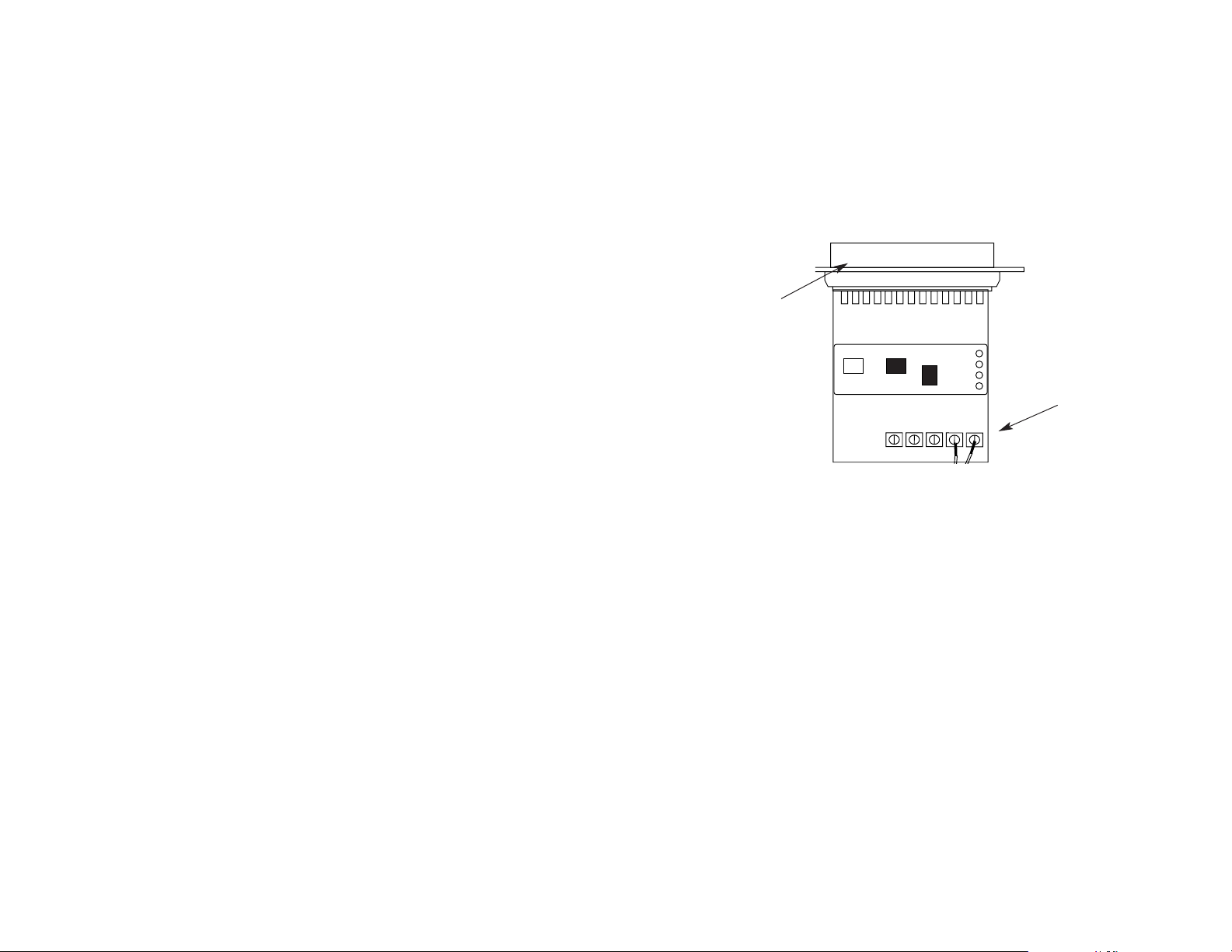
3.0 CONFIGURATION
The Model 2084 does not require configuration. Model 2084 is
factory configured as Data Circuit Terminating Equipment (DCE). That
is, it “wants” to connect to Data Terminal Equipment (DTE) via its DB-25
RS-232 port. Figure 1 (below) shows the RS-232 DB-25 connector and
terminal blocks on the printed circuit board.
4
DB-25
Connector
Terminal
Blocks
Figure 1. Top view of Model 2084 board
+RCV- G -XMT+
Page 4

4.0 INSTALLATION
This section tells you how to properly connect the Model 2084 to
the RS-232 and RS-485 interfaces, and how to operate the Model 2084.
4.1 CONNECTING THE RS-485 INTERFACE
The RS-485 interface is factory configured as Data Circuit
Terminating Equipment (DCE). Therefore, it “wants” to connect directly
to Data Terminal Equipment (DTE) such as a terminal or PC. If you
must use a cable to connect to the DTE, use a
straight-through
cable
no longer than 50 feet.
4.2 CONNECTION TO THE RS-485 INTERFACE
To function properly, the Model 2084
must
have one twisted pairs
of metallic wire. This pair must be "dry" (unconditioned) metallic wire,
between 19 and 26 AWG (the higher number gauges may limit distance
somewhat).
For your convenience, the Model 2084 is available with several
different physical interfaces on the RS-485 side: RJ-11 jack, RJ-45
jack, and terminal blocks with strain relief.
5
4.2.1 Connecting via the RJ-11 Connector
The RJ-11 version of Model 2084 uses an RJ-11 connector on the
RS-485 side. The RJ--11 connector is prewired for a standard TELCO
wiring environment. The signal/pin relationships are shown below in
Figure 2.
When connecting the
twisted pair
cable from the 2084’s RJ-11 jack to
the RS-485 device, your cable must be connected in the manner shown
below.
MODEL 2084 RS-485 DEVICE
SIGNAL
PIN# RS-485 SIGNAL
GND
*
1
n/c 2
XMT+ 3 XMT A
XMT- 4 XMT Bn/c 5
GND
*
6
*Connection to ground is optional
6
1
2
3
4
5
6
1 Ground
2 (no connection)
3 TX Data + (XMT+)
4 TX Data - (XMT-)
5 (no connection)
6 Ground
Figure 2. RJ-11 Twisted Pair Pin/Signal Relationships
Page 5

4.2.2 Connecting via the RJ-45 Connector
The RJ-45 version of Model 2084 uses an RJ-45 connector on the
RS-485 side. The RJ-45 connector is prewired for a standard TELCO
wiring environment. The signal/pin relationships are shown below in
Figure 3.
When connecting the
twisted pair
cable from the 2084’s RJ-45 jack to
the RS-485 device, your cable must be connected in the manner shown
below.
MODEL 2084 RS-485 DEVICE
SIGNAL
PIN# RS-485 SIGNAL
N/C 1
GND
*
2
N/C 3
XMT+ 4 XMT A
XMT- 5 XMT BN/C 5
GND
*
7
N/C 8
*Connection to ground is optional
7
1
2
3
4
5
6
7
8
1 (no connection)
2 Ground
3 (no connection)
4 (TX Data + (XMT+)
5 (TX Data - (XMT-)
6 (no connection)
7 (Ground)
8 (no connection)
Figure 3. RJ-45 Twisted Pair Line Interface
4.2.3 4-WIRE CONNECTION USING TERMINAL BLOCKS
If your RS-485 application requires you to connect one pair of bare
wires to the Model 2084, you will need to open the case to access the
terminal blocks. The following instructions will tell you how to open the
case, connect the bare wires to the terminal blocks, and fasten the
strain relief collar in place so that the wires won't pull loose.
1. If the case is not already open, open it now by twisting it open
with a small plastic screwdriver.
2. Strip the outer insulation from the twisted pairs about one inch
from the end.
3. Strip back the insulation on each of the 2 twisted pair wires
about .25".
4. Connect
one pair
of wires to XMT+ and XMT- (transmit positive
and negative) on the terminal block, making careful note of which color
is positive, and which color is negative.
5. Connect the same
pair
of wires to XMT A and XMT B on the RS-
485 Device, respectively.
Ultimately, you will want to construct a two pair cross over cable that
makes a connection with the RS-485 device as shown below:
Model
2084 RS-485 Device
XMT+ XMT A
XMT- XMT B
8
Page 6

6. Place the 2 halves of the strain relief assembly on either side of
the telephone wire and press together very lightly. Slide the assembly
so that it is about 2 inches from the terminal posts and press together
firmly. If your cable diameter is too small or too large for our strain
relief, please contact our technical support. We have strain relief
assemblies to accommodate most cable diameters.
7. Insert the strain relief assembly with the wire going through it
into the slot in the bottom half of the modem case and set it into the
recess in the case.
8. BEND the top half of the case as necessary to place it over the
strain relief assembly. Do not snap the case together yet.
9. Insert one captive screw through a saddle washer and then
insert the captive screw with the washer on it, through the hole in the
DB-25 end of the case. Snap that side of the case closed. Repeat the
process for the other side. This completes the cable installation
process.
9
4.3 OPERATING THE MODEL 2084
Once the Model 2084 is properly installed, it should operate
transparently—as if it were a standard cable connection. Operating
power is derived from the RS-232 data and control signals; there is no
“ON/OFF” switch. All data signals from the RS-232 and RS-485
interfaces are passed straight through.
10
Page 7

APPENDIX A
PATTON ELECTRONICS MODEL 2084
SPECIFICATIONS
Transmission Format: Asynchronous
Data Rate: Up to 115,200 bps
Range: Up to 4000 feet @ 9600 bps
RS-232 Interface: DB-25
RS-485 Interface Options: RJ-11 or RJ-45 jack; terminal block
with strain relief
Transmit Line: 2 wire unconditioned twisted pair
Transmit Mode: 2-wire half duplex
Surge Protection: 600W power dissipation at 1 mS
Power: Draws operating power from RS-
232 data and control signals; no
AC power or batteries required.
Temperature: 0 to 50º C
Humidity: 5 to 95%, non-condensing
Size: 2.66” x 2.10” x 0.73”
11
APPENDIX B
PATTON ELCTRONICS MODEL 2084 RS-232 PIN
CONFIGURATIONS
Copyright © 1998
Patton Electronics Company
All Rights Reserved
12
1- (FG) Frame Ground
2- (TD) Transmit Data To Model 2084
3- (RD) Receive Data From Model 2084
4- (RTS) Request to Send To Model 2084
5- (CTS) Clear to Send From Model 2084
6- (DSR) Data Set Ready From Model 2084
7- (SG) Signal Ground
8- (DCD) Data Carrier Detect From Model 2084
To Model 2084 Data Term. Ready (DTR) - 20
DIRECTION “DCE” ORIENTATION DIRECTION
 Loading...