

Page 1
USER
MANUAL
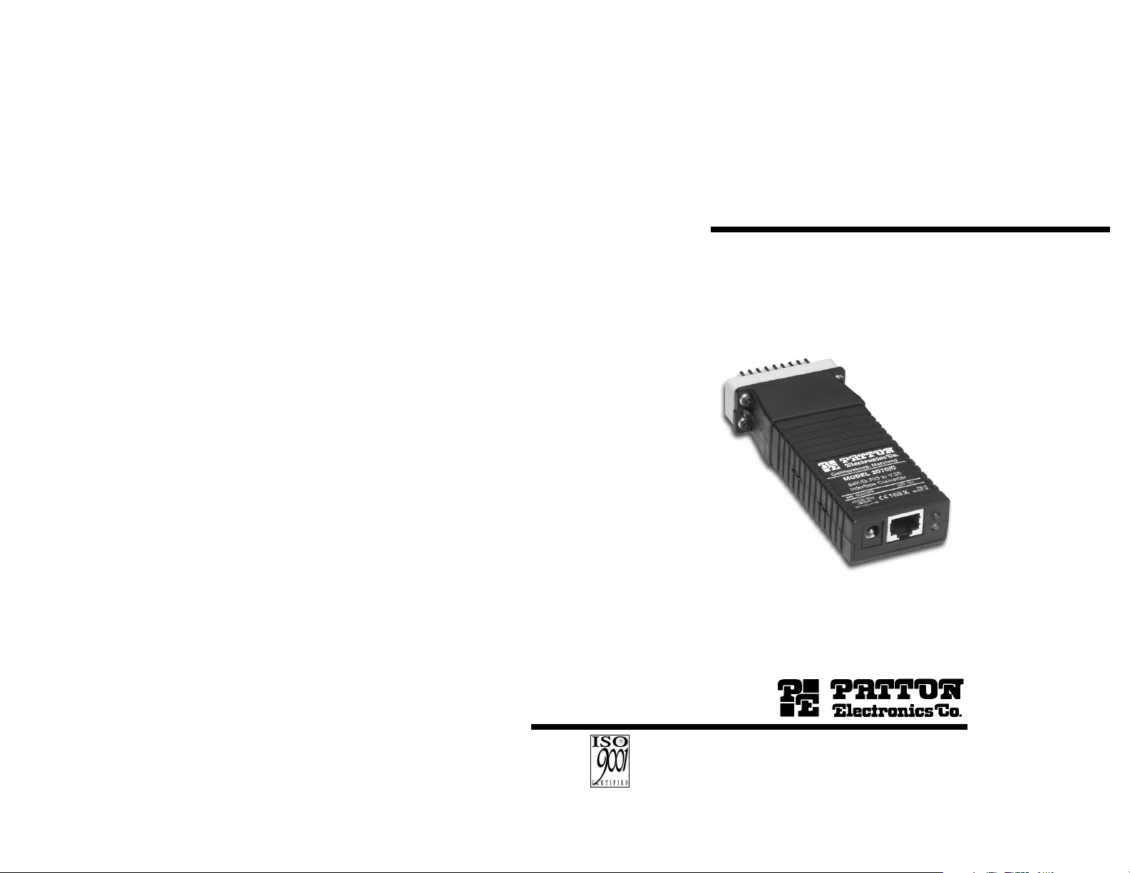
Model 2070 Series
V.24/X.21/V.35 to G.703
Interface Converter
SALES OFFICE
(301) 975-1000
TECHNICAL SUPPORT
(301) 975-1007
http://www.patton.com
Part# 07M2070-UM
Doc# 03106U2-001,
Rev. D
Revised 10/25/06
An ISO-9001
Certified Company
CERTIFIED
Page 2

TABLE OF CONTENTS
Section Page
1.0 Warranty Information.............................................................2
1.1 Radio and TV Interference
1.2. CE Notice
1.3 Service Information
2.0 General Information...............................................................4
2.1 Product Features
2.2 General Product Description
3.0 Configuration .........................................................................5
3.1 Opening the Case
3.2 Configuration (Model 2070/Ax
V.24 Version)
3.3 Configuration (Model 2070/Cx V.35 Version)
3.4 Configuration (Model 2070/Dx X.21 Version)
4.0 Installation ...........................................................................18
4.1 Connecting Over a PCM Network Channel
4.2 Connecting over Private Twisted Pair
4.3 DTE (Terminal) Connection
4.4 Power Connection
5.0 Operation.............................................................................21
5.1 LED Status Monitors
5.2 Test Mode
Appendix A - Specifications........................................................23
Appendix B - Cable Recommendations......................................24
Appendix C - Factory Replacement Parts & Accessories...........25
Appendix D - Interface Pin Assignments ....................................26
Appendix E - Block Diagram.......................................................28
1
2
1.0 WARRANTY INFORMATION
Patton Electronics warrants all Model 2070 Series components to
be free from defects, and will—at our option—repair or replace the
product should it fail within one year from the first date of shipment.
This warranty is limited to defects in workmanship or materials, and
does not cover customer damage, abuse or unauthorized modification.
If this product fails or does not perform as warranted, your sole
recourse shall be repair or replacement as described above. Under no
condition shall Patton Electronics be liable for any damages incurred
by the use of this product. These damages include, but are not limited
to, the following: lost profits, lost savings and incidental or
consequential damages arising from the use of or inability to use this
product. Patton Electronics specifically disclaims all other warranties,
expressed or implied, and the installation or use of this product shall be
deemed an acceptance of these terms by the user.
1.1 RADIO AND TV INTERFERENCE
The Model 2070 generates and uses radio frequency energy, and if
not installed and used properly—that is, in strict accordance with the
manufacturer’s instructions—may cause interference to radio and
television reception. The Model 2070 has been tested and complies
with the limits for a Class A computing device in accordance with the
specification in Subpart J of Part 15 of FCC rules, that are designed to
provide reasonable protection from such interference in a commercial
installation. However, this is no guarantee that interference will not
occur in a particular installation. If the Model 2070 does cause
interference to radio or television reception, which can be determined
by disconnecting the unit, the user is encouraged to try to correct the
interference by one or more of the following measures: moving the
computing equipment away from the receiver, reorienting the receiving
antenna and/or plugging the receiving equipment into a different AC
outlet (such that the computing equipment and receiver are on different
branches).
In the event the user detects intermittent or continuous product
malfunction due to nearby high power transmitting radio frequency
equipment, the user is strongly advised to use only a shielded twisted
pair data cable that is bonded to metalized external outer shield plugs
at both ends. The use of a shielded cable satisfies compliance with the
Electromagnetic Compatibility (EMC) directive by allowing proper
shielding of the network connection.
Page 3

1.2 CE NOTICE
The CE symbol on your Patton Electronics equipment indicates
that it is in compliance with the Electromagnetic Compatibility (EMC)
directive and the Low Voltage Directive (LVD) of the Union European
(EU). A Certificate of Compliance is available by contacting Technical
Support.
1.3 SERVICE
All warranty and nonwarranty repairs must be returned freight
prepaid and insured to Patton Electronics. All returns must have a
Return Materials Authorization number on the outside of the shipping
container. This number may be obtained from Patton Electronics
Technical Service: (301) 975-1007, http://www.patton.com;
support@patton.com.
NOTE: Packages received without an RMA number will not be
accepted.
Patton Electronics’ technical staff is also available to answer any
questions that might arise concerning the installation or use of your
Model 2070. Technical Service hours: 8AM to 5PM EST, Monday
through Friday.
3
2.0 GENERAL INFORMATION
Thank you for your purchase of this Patton Electronics product.
This product has been thoroughly inspected and tested and is
warranted for One Year parts and labor. If any questions or problems
arise during installation or use of this product, please do not hesitate to
contact Patton Electronics Customer Service at (301) 975-1007.
2.1 FEATURES
• Bi-directionally converts V.24, X.21 or V.35 to co-directional G.703
• Operates at 64 kbps synchronous data rate
• LED indicators monitor Test Mode and Synchronization
• Internal, external or network clocking options (External clocking on
V.24 and V.35 versions only)
• Test Mode controlled by switch or by local DTE (V.24 and V.35
Versions Only)
• Complies with CCITT/ITU G.823 Jitter Control Specifications
• Built-in surge protection and transformer isolation
• Point-to-Point distance up to 5250 ft (1600m) on 24 AWG twisted
pair
• 120 ohm (twisted pair) network termination
2.2 DESCRIPTION
The Patton Model 2070 Miniature Interface Converters allow a
synchronous V.24, V.35, or X.21 device to communicate bi-directionally
over the G.703 co-directional PCM network. Supporting internal,
external DTE timing or G.703 network generated timing, the Model
2070 is perfect for networking applications that require a single 64
kbps data channel.
The Model 2070 connects directly to the synchronous DTE using
a DB-25 connector (Model 2070/Ax), an M/34 connector (Model
2070/Cx) or a DB-15 connector (2070/Dx). A 120 ohm twisted pair
telephone port provides the interface for the G.703 network.
Additionally, 75 ohm terminations can be made using the Patton Model
460 (G.703 balun).
Diagnostics include Local Loopback and G.703 Loopback testing.
Synchronous clock jitter is attenuated in accordance with the G.823
specification.
4
Page 4
3.0 CONFIGURATION
The Model 2070 is easy to install and is ruggedly designed for
excellent reliability. The following instructions will help you set up and
install the Model 2070 properly.
3.1. OPENING THE CASE
To use the Patton Model 2070, you must first configure the unit for
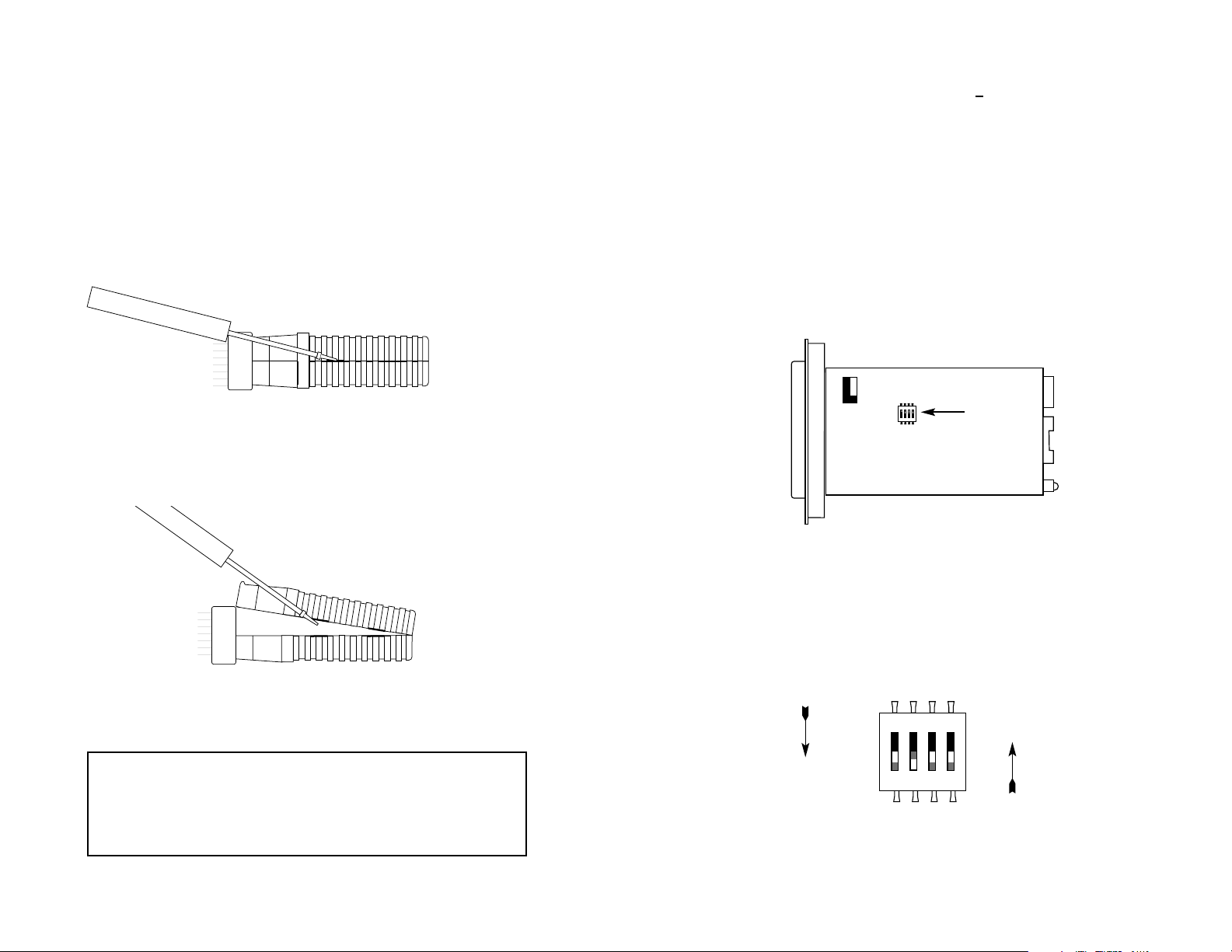
your application. To do so, first open the case by inserting a flat head
screw driver into an open slot on either side of the case, as in Figure 1.
Twist the screw driver head slightly and the top half of the case will
separate from the lower half, as in Figure 2. You now have access to
the internal switches used to configure the unit.
After opening the case, please refer to the section that pertains to
your unit for configuration details.
5
Figure 1. How to Use a Small Flathead Screwdriver to Begin to Open the Model 2070 Case
Figure 2: How to Use a Small Flathead Screwdriver to Finish Opening the Model 2070 Case
Notice! The RJ-45 G.703 port of the Model 2070 is intended
to connect to telecommunication network voltage (TNV)
circuits which may carry dangerous voltages. Therefore the
power and network cables must be disconnected prior to
switch and jumper configuration.
3.2 CONFIGURATION (MODEL 2070/Ax V.24 VERSION)
The Model 2070/Ax uses a mini DIP switch package and jumper
strap that allow configuration to a wide range of applications. The
switch and the jumper are located on the bottom side of the PC Board.
Follow the instructions below to configure the 2070/Ax (V.24 Version).
See Section 3.3 to configure the Model 2070/Cx (V.35 Version) or
Section 3.4 to configure the Model 2070/Dx (X.21 Version)
3.2.1 Configuration Switch Set “S1”
The four switches on DIP Switch S1 are used to select the test
mode and clock mode functions. Figure 3 shows the position of Switch
S1 on the bottom side of the Model 2070/Ax PC board.
Figure 4 shows the orientation of the Switches on DIP Switch S1
with respect to ON/OFF positions. The default settings for DIP switch
S1 are shown in the table on page 7. Detailed descriptions of each
switch follow the table.
6
Figure 4. Close-up of DIP Switches Showing “ON” and “OFF” Positions
Figure 3. Location of Switch S1 on the bottom of the Model 2070/Ax PC board
OFF
ON
Switch S1
1234
1234
ON
ON
1234
Page 5
Switches S1-1: Test Mode Activation
Use Switch S1-1 to enable or disable the Model 2070/Ax Test
Mode. When enabled, the Local Line and G.703 loopback tests
activate simultaneously. When disabled, the Model 2070/Ax functions
normally.
S1-1
Activation Description
On Enabled Local Loop and G.703 Loop
diagnostics enabled
Off Disabled Local Loop and G.703 Loop
diagnostics disabled
Switches S1-2 and S1-3: Clocking Mode
Use Switches S1-2 and S1-3 together to set the system clock for
the Model 2070/Ax. When using two Model 2070s together in a pointto-point application as short range modems, set one unit for either
Internal or External transmit clock and the other unit to Network clock.
When connecting directly to the G.703 network, set the unit to Network
clock.
S1-2 S1-3 Clocking Description
On On Network The G.703 network
provides the system clock
On Off External The DTE provides the
system clock
Off On Internal The Model 2070/Ax
provides an internally
generated system clock
7
2070/Ax SWITCH S1 SUMMARY TABLE
Position Function Factory Default
S1-1 Test Mode Off Disabled
S1-2 Clock Mode On
S1-3 Clock Mode On
S1-4 Respond to LL Request On Disabled
}
Network
Clock
8
Switch S1-4: Response to DTE Request for Local Loopback
Use Switch S1-4 to enable the Model 2070/Ax to enter Local
Loopback mode when pin 18 from the V.24 interface is raised. In the
On position, the Local Loopback may only be enabled manually by
Switch S1-1.
S1-4 Activation Description
On Disabled Model 2070/Ax ignores DTE
requests to enter Local Loopback
Off Enabled Model 2070/Ax enters Local
Loopback Mode when pin 18 is
raised
3.2.2 Jumper Straps “JP1” and “JP2”
The Model 2070/Ax uses two jumper straps to select the power
source option and to connect the unit signal ground to frame ground.
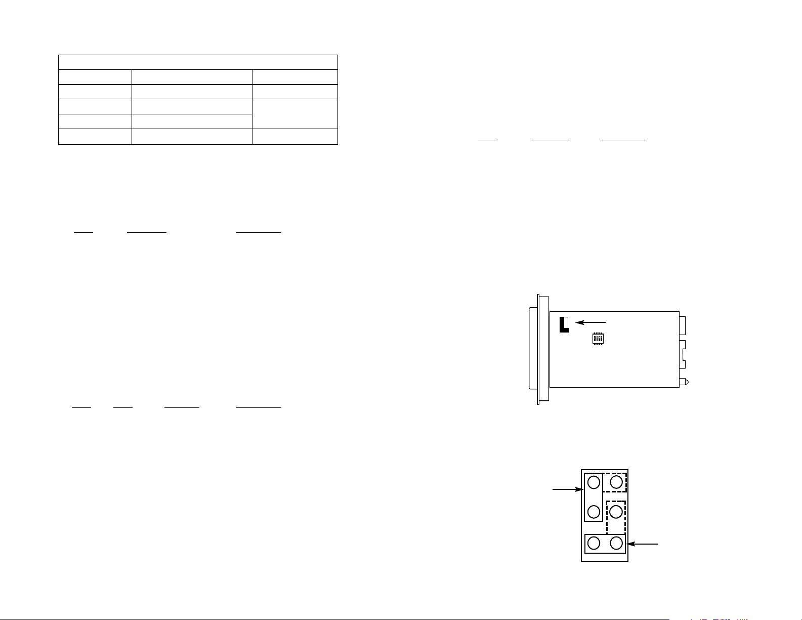
Figure 5 (below) shows the position of Jumper Straps JP1 and JP2 on
the bottom side of the Model 2070/Ax PC board.
Figure 6 shows possible settings of jumper straps JP1 and JP2.
JP1 may be positioned on pegs 1 and 2 or on pegs 1 and 3; JP2 may
be positioned on pegs 4 and 6 or on pegs 5 and 6.
Figure 5. Location of Strap JP1 and JP2 on the bottom of the Model 2070/Ax PC board
Figure 6. Possible Settings of Jumper Straps JP1 and JP2
1
3
5
2
4
6
Jumpers JP1
& JP2
1
2
3
5
6
JP2
JP1
4
1234
ON
Page 6

Jumper JP1: Power Source
The Model 2070/Ax may be powered by the RS-232 interface or by
the supplied AC wall-mount transformer. The setting for JP1
determines how the Model 2070/Ax receives its operating power.
JP1
Position 1&2 Interface Power Option. In this setting the
2070/Ax is powered from the DTE
interface. Power should be applied to DB-25
pin 9 at +5VDC (±5%), 300mA (min). The AC
wall-mount transformer must not be
connected in this setting.
Position 1&3 AC Power Option. In this setting, the 2070/Ax
is powered by the AC wall mount transformer
Jumper JP2: SGND & FRGND
In the default position, Signal Ground is connected to Frame
Ground. In the disconnected position, this strap disconnects Signal
Ground and Frame Ground.
Position 4&6 G.703 FRGND connected to DTE FRGND.
Both are disconnected from SGND
.
Position 5&6 G.703 FRGND connected to DTE FRGND
Both are connected to SGND
(default)
.
9
2070/Ax JP1 AND JP2 SUMMARY TABLE
Position Function Factory Default
JP1 Power Source 1&3 AC Powered
JP2 SGND to FGND 5&6 Connected
3.3 CONFIGURATION (MODEL 2070/Cx -- V.35 VERSION)
The Model 2070/Cx uses a mini DIP switch package and a jumper
strap that allow configuration to a wide range of applications. The
switch is located on the bottom side and the jumper strap is located on
the top side of the PC board. Follow the instructions below to configure
the 2070/Cx (V35 Version). See Section 3.2 to configure the Model
2070/Ax (V.24 Version) or Section 3.4 to configure the Model
2070/Dx (X.21 Version).
3.3.1 Configuration Switch Set “S1”
The four switches on DIP Switch S1 are used to select the test
mode and clock mode functions. Figure 7 shows the position of Switch
S1 on the bottom side of the Model 2070/Cx.
Figure 8 shows the orientation of the Switches on DIP Switch S1
with respect to ON/OFF positions. The default settings for DIP switch
S1 are shown in the table on the following page. Detailed descriptions
of each switch follow the table.
10
Figure 8. Close-up of DIP Switches Showing “ON” and “OFF” Positions
OFF
ON
Figure 7. Location of Switch S1 on the bottom of the 2070/Cx PC board
Switch S1
1234
ON
1234
ON
1234
Page 7

Switches S1-1: Test Mode Activation
Use Switch S1-1 to enable or disable the Model 2070/Cx Test
Mode. When enabled, the Local Line and G.703 loopback tests are
activated simultaneously. When disabled, the Model 2070/Cx functions
normally.
S1-1
Activation Description
On Enabled Local Loop and G.703 Loop
diagnostics enabled
Off Disabled Local Loop and G.703 Loop
diagnostics disabled
Switches S1-2 and S1-3: Clocking Mode
Use Switches S1-2 and S1-3 together to set the system clock for
the Model 2070/Cx. When using two Model 2070s together in a pointto-point application as short range modems, set one unit for either
Internal or External transmit clock and the other unit to Network clock.
When connecting directly to the G.703 network, set the unit to Network
clock.
S1-2 S1-3 Clocking Description
On On Network The G.703 network
provides the system clock
On Off External The DTE provides the
system clock
Off On Internal The Model 2070/Cx
provides an internally
generated system clock
11
MODEL 2070/Cx SWITCH S1 SUMMARY TABLE
Position Function Factory Default
S1-1 Test Mode Off Disabled
S1-2 Clock Mode On
S1-3 Clock Mode On
S1-4 Response to LL Request On Disabled
}
Network
Clock
Switch S1-4: Response to DTE Request for Local Loopback
Use Switch S1-4 to enable the Model 2070/Cx to enter Local
Loopback mode when pin L from the V.35 interface is raised. In the On
position, the Local Loopback may only be enabled manually by Switch
S1-1.
S1-4 Activation Description
On Disabled Model 2070/Cx ignores requests
to enter Local Loopback
Off Enabled Model 2070/Cx enters Local
Loopback Mode when pin 18 is
raised
3.3.2 Jumper Straps “JP1” and “JP2”
The Model 2070/Cx uses two jumper straps (JP1 and JP2, see
Figure 9 below) to select the power source option and to connect the
unit signal ground to frame ground.
Figure 10 shows possible settings of jumper straps JP1 and JP2.
JP1 may be positioned on pegs 1 and 2 or on pegs 1 and 3. JP2 may
be positioned on pegs 4 and 6 or on pegs 5 and 6.
12
Figure 9. Location of Jumpers JP1 and JP2 on the top of the Model 2070/Cx PC board
Figure 10. Possible Settings of Jumper Straps JP1 and JP2
1
2
3 4
5
6
JP2
JP1
1
3
5
2
4
6
Jumpers JP1
& JP2
Page 8

Jumper JP1: Power Source
The Model 2070/Cx may be powered by the V.35 interface or by
the supplied AC wall-mount transformer. The setting for JP1
determines how the Model 2070/Cx receives its operating power.
JP1
Position 1&2 Interface Power Option. In this setting the
2070/Cx Series unit is powered from the DTE
interface. Powered should be applied to M/34
pin KK at +5VDC (±5%), 300mA (min) The AC
wall-mount transformer must not be
connected in this setting.
Position 1&3 AC Power Option. In this setting, the 2070/Cx
is powered by the AC wall mount transformer
(default)
.
Jumper JP2: SGND & FRGND
In the default position, Signal Ground is connected to Frame
Ground. In the disconnected position, this strap disconnects Signal
Ground and Frame Ground.
Position 4&6 G.703 FRGND connected to DTE FRGND.
Both are disconnected from SGND
.
Position 5&6 G.703 FRGND connected to DTE FRGND
Both are connected to SGND
(default)
.
13
2070/Cx JP1 AND JP2 SUMMARY TABLE
Position Function Factory Default
JP1 Power Source 1&3 AC Powered
JP2 SGND to FGND 5&6 Connected
3.4 CONFIGURATION (MODEL 2070/Dx -- X.21 VERSION)
The Model 2070/Dx uses a mini DIP switch package and a jumper
strap that allow configuration to a wide range of applications. The
switch is located on the bottom side and the jumper strap is located on
the top side of the PC board. Follow the instructions below to configure
the 2070/Dx (X.21 Version). See Section 3.2 to configure the Model
2070/Ax (V.24 Version) or Section 3.3 to configure the Model
2070/Cx (V.35 Version).
3.4.1 Configuration Switch Set “S1”
The four switches on DIP Switch S1 are used to select the test
mode and clock mode functions. Figure 11 shows the position of
Switch S1 on the bottom side of the Model 2070/Dx.
Figure 12 shows the orientation of the Switches on DIP Switch S1
with respect to ON/OFF positions. The default settings for DIP switch
S1 are shown in the table on the following page. Detailed descriptions
of each switch follow the table.
14
Figure 11. Location of Switch S1 on the bottom of the 2070/Dx PC board
Figure 12. Close-up of DIP Switches Showing “ON” and “OFF” Positions
OFF
ON
Switch S1
1234
1234
ON
ON
1234
Page 9

Switches S1-1: Test Mode Activation
Use Switch S1-1 to enable or disable the Model 2070/Dx Test
Mode. When enabled, the Local Line and G.703 loopback tests are
activated simultaneously. When disabled, the Model 2070/Dx functions
normally.
S1-1
Activation Description
On Enabled Local Loop and G.703 Loop
diagnostics enabled
Off Disabled Local Loop and G.703 Loop
diagnostics disabled
Switch S1-2 : Clocking Mode
Use Switch S1-2 to set the system clock for the Model 2070/Dx.
When using two Model 2070s together in a point-to-point application as
short range modems, set one unit for Internal clock and the other unit
to Network clock. When connecting directly to the G.703 network, set
the unit to Network clock.
S1-2
Clocking Description
On Network The G.703 network
provides the system clock
Off Internal The Model 2070/Dx provides
an internally generated
system clock
15
MODEL 2070/Dx SWITCH S1 SUMMARY TABLE
Position Function Factory Default
S1-1 Test Mode Off Disabled
S1-2 Clock Mode On Network
S1-3 Byte Timing On Enabled
S1-4
Reserved
Off
Switch S1-3: Byte Timing
Use Switch S1-3 to enable byte timing on the Model 2040/Dx. The
Byte timing clock is an 8 KHz (1 byte/sync. pulse) framing clock
synchronized to the G.703 Data.
S1-3 Activation Description
On Enabled Model 2070/Dx outputs Byte Timing
Off Disabled Byte timing is disabled
Switch S1-4: Reserved for Factory Use
Switch S1-4 is reserved for factory use and must remain in the
Off position.
S1-4
Activation
On Not a Valid Setting
Off Normal Operation
3.4.2 Jumper Strap “JP1” and “JP2”
The Model 2070/Dx uses two jumper straps (JP1 and JP2, see
Figure 13 below) to select the power source option and to connect the
unit signal ground to frame ground.
.
Figure 14 (following page) shows possible settings of jumper straps
JP1 and JP2. JP1 may be positioned on pegs 1 and 2 or on pegs 1
and 3; JP2 may be positioned on pegs 4 and 6 or on pegs 5 and 6. A
detailed description of each jumper strap follows Figure 14.
16
Figure 13. Location of Strap JP1 and JP2 on the top of the Model 2070/Dx PC board
Jumpers JP1 & JP2
1
3
5
2
4
6
Page 10

Jumper JP1: Power Source
The Model 2070/Dx may be powered by the X.21 interface or by
the supplied AC wall-mount transformer. The setting for JP1
determines how the Model 2070/Dx receives its operating power.
JP1
Position 1&2 Interface Power Option. In this setting the
2070/Dx is powered from the DTE
interface. Power should be applied to DB-15
pin 15 at +5VDC (±5%), 300mA (min) The AC
wall-mount transformer must not be
connected in this setting.
Position 1&3 AC Power Option. In this setting, the 2070/Dx
is powered by the AC wall mount transformer
Jumper JP2: SGND & FRGND
In the default position, Signal Ground is connected to Frame
Ground. In the disconnected position, this strap disconnects Signal
Ground and Frame Ground.
Position 4&6 G.703 FRGND connected to DTE FRGND.
Both are disconnected from SGND
.
Position 5&6 G.703 FRGND connected to DTE FRGND
Both are connected to SGND
17
2070/Dx JP1 AND JP2 SUMMARY TABLE
Position Function Factory Default
JP1 Power Source 1&3 AC Powered
JP2 SGND to FGND 5&6 Connected
Figure 14. Possible Settings of Jumper Straps JP1 and JP2
1
2
3 4
5
6
JP2
JP1
4.0 INSTALLATION
The Model 2070 is designed for 4-wire, full duplex communication
over a co-directional 64 kbps G.703 clear channel network or dedicated
twisted pair. This section describes the proper connection of the line
interface, the DTE (terminal) interface, and AC/DC power.
4.1 CONNECTING TO A PCM NETWORK CHANNEL
The RJ-45 port on a Model 2070 is pre-wired for direct connection
to the G.703 PCM network. Connect the RJ-45 port of the Model 2070
to the RJ-45 jack provided by your digital service carrier using a
straight through twisted pair cable between 19 and 26 AWG. To be
sure you have the right wiring, use the diagram below as a guide.
4.2 CONNECTING OVER PRIVATE TWISTED PAIR
If you wish to connect the Model 2070 to another Model 2070 (or
compatible G.703 device) over private twisted pair, make the
connection between the two devices using a crossover cable pinned
according to the diagram below.
RJ-45 Cable (8-W
ire)
SIGNAL PIN# PIN# SIGNAL
RX+ 1-----------------------5 TX+
RX- 2-----------------------4 TXTX+ 5-----------------------1 RX+
TX- 4-----------------------2 RX
Shield 3-----------------------3 Shield
Shield 6-----------------------6 Shield
18
1 (RX+)
2 (RX-)
3 (N/C)
4 (TX-)
5 (TX+)
6 (N/C)
7 (N/C)
8 (N/C)
1
2
3
4
5
6
7
8
Notice! The G.703 line surge protection on this unit was
installed for circuit protection only. By no means does this
include the preservation of signal quality during a large surge.
Page 11

4.4.3 Interface Power Option
The Model 2070 can also be powered by the appropriate V.24, V.35 or
X.21 interface pin (See Appendix D). Voltage supplied should be +5V
(±5%) regulated DC, 300mA min. When powered by the interface,
the power transformer must not be connected.
4.4.4 DC Power Supply
The 36-60 VDC DC to DC adapter is supplied with the DC version of
the Model 2070. The black and red leads plug into a DC source
(nominal 48VDC) and the barrel power connector plugs into the barrel
power supply jack on the 2070.
20
Notice! If any version of the Model 2070 is to be powered by
the host interface, please refer to the host’s installation manual
and ensure that the combined power required by the host, and
the total of all the additional peripherals, installed both
externally and internally, does not exceed the power
specifications of the host apparatus
4.3 DTE (TERMINAL) CONNECTION
The V.24, V.35 or X.21 side of the Model 2070 Series units are
wired as a DCE and support a wide range of applications. You may
purchase adapter cables from Patton Electronics. If you would like to
construct your own interface cable, refer to the pinout diagrams in
Appendix D or contact Patton Electronics Technical Support: (301)
975-1007; support@patton.com;orhttp://www.patton.com for
specific interface pin assignments.
4.4 POWER CONNECTION
The 120VAC U.S. wall transformer version supplies +5V regulated
DC up to 300mA. The variable 110/230VAC “international” version
supplies +5V regulated DC up to 2A. Either of these transformers
connect to the Model 2070 by means of a cannon jack on the rear
panel. The Model 2070 is powered-up as soon as it is plugged into an
AC outlet–there is no power switch.
4.4.1 120 VAC Power (US)
The 100-132 VAC adapter supplied with the U.S. version of the
Model 2070 is a wall mount type and may be plugged into any
approved 120 VAC wall plug.
4.4.2 230 VAC Power (IEC)
The variable 100-240 VAC adapter supplied with the “international”
version of the Model 2070 is equipped with an IEC-320 shrouded male
connector. This connects with one of several available country-specific
power cords (see the ordering information in Appendix C). You may
purchase these power cords from Patton Electronics, or from a vendor
of your choice.
(continued)
19
Notice! Any line or terminal cable connected to the Model
2070 Series must be shielded cable, and the outer shield must
be 360 degree bonded–at both ends–to a metal or metalized
backshell.
To Power
Supply Jack
Barrel power connector
S/N: G01234567890
MADE IN CHINA BY SUNNY
SWITCHING POWER SUPPLY
MODEL : SYD1106-0505
INPUT : 36-60V 0.2A MAX
OUTPUT : +5V 1.0A
OUTPUT POWER : 5W MAX
-Vin
+Vin
To -48VDC
Source
Black lead (-V)
Red lead (+V)
Page 12

5.0 OPERATION
Once you have configured the Model 2070 properly (see Section
3.0) and made line, DTE and power connections correctly (see Section
4.0), you are ready to operate the unit(s). This section describes the
LED status monitors, and the loopback test mode.
5.1 BACK PANEL LED STATUS MONITORS
The Model 2070 features two LEDs that are located on the back
panel. Figure 11 below shows the positions of the LEDs. Following
Figure 15 is a description of each LED.
TM glows RED when Test Mode (Local Loop/G.703 Loop) is
initiated manually or by the DTE (See Section 3.0).
SYNC glows GREEN to indicate a valid G.703 synchronization to the
terminal device. No signal indicates no data, no connection or
synchronous clock slippage on either the G.703 side or the
terminal device side.
5.2 TEST MODE
The Model 2070 offers a Test Mode that may be used to evaluate
the condition of the modems and the communication link. Test Mode is
composed of two diagnostics that are activated simultaneously either by
DIP Switch S1-1 or by a signal on the terminal interface. This section
describes the two Test Mode diagnostics: Local Loop and G.703 Loop.
Local Loop
The Local Loop test checks the operation of the local 2070 on the
terminal device side by echoing any data sent to the Model 2070 back to
the user device. For example, characters typed on the keyboard on the
terminal will appear on the terminal screen (See Figure 16, following
page)
21
TM
SYNC
Power Jack
RJ45 Jack
Figure 15. Model 2070 back panel LED indicators
22
G.703 Loop
The G.703 Loop test allows the G.703 service provider to test the
condition of the twisted pair communication link between itself and the
Model 2070. Using this test, the service provider sends BER (Bit Error
Rate) signals to the Model 2070 over the twisted pair wire. The Model
2070 senses these signals and loops the digital data back to the central
office (Figure 16, below).
5.2.1 Test Mode Activation
1. Notify the G.703 Service provider that you wish to perform a
G.703 Loop test.
2. To Activate the Model 2070 Test Mode:
a. Move Switch S1-1 to the “ On “ position; OR,
b. Set Switch S1-4 to the Off (Enabled) position. Then
raise the appropriate “Loop Control” (LC) pin on the
terminal interface (see Appendix D).
When Test Mode is activated, both the Local Loop and G.703
Loop diagnostics are active: The terminal device’s transmitter
will be “looped” to its own receiver. Similarly, the G.703
transmitter output is connected to its own receiver input.
3. Perform a BER (bit error rate) test from the terminal interface.
If the BER test equipment indicates no faults, but the data
terminal indicates a fault, follow the manufacturer’s checkout
procedures for the data terminal. While the Test Mode is
activated, the TM light will illuminate Red.
4. The service provider may also perform a loop or BER test on
the G.703 communication link. If the loop or BER test
indicates a fault, the twisted pair connection may be faulty.
Model 2070
Figure 16 Test Mode Operation: Local Loop/G.703 Loop
Local
Loop
G.703
Loop
Digital Network
Page 13

APPENDIX A
PATTON MODEL 2070 SPECIFICATIONS
Approvals: CE Mark
Compliance: FCC Class A, EN 55022, (EMC Emissions)
EN 50082-1, (EMC Susceptibility)
EN 60950, (LVD Safety)
CTR 14, (Type Approval) - The
symbol indicates that the Model 2070 is in
compliance with the applicable Telecom
Directive of the EU. If your 2070 is marked
with this symbol, it is EU Telecom Type
Approved and may be connected to the
public network.
Applications: 64K G.703 co-directional PCM network or
CSU/DTE conversion to CCITT/ITU V.24,
CCITT/ITU V.35, or CCITT/ITU X.21
G.703 Interface: Symmetrically balanced pairs, 4 wire, 120
Ohm terminated to female RJ-45
Terminal Interface: Model 2070/Ax CCITT/ITU V.24 Sync.,
DCE
Model 2070/Cx CCITT/ITU V.35 Sync.,
DCE
Model 2070/Dx CCITT/ITU X.21 Sync.,
DCE
Operating Speed: Co-directional timing, Rx recovered:
64Kbits +
500ppm
Clocking: Internal, External or Network Timing
(External Timing on 2070/Ax and 2070/Cx
Only)
G.703 Input Sig. Level: 2.0V differential, into 100 Ohms, nominal
Max. Cable Loss: 0 to -10dB
Line Encoding: AMI
Jitter Performance: CTR 14, G.823
Surge Protection: Complies with IEC 801-5 Level 1, 500V
Isolation: 1500 VRMS isolation, transformer coupled
Indicators: LED’s monitor TM and SYNC
Power Supply Options: External wall-mount transformer:
100-240 VAC Input to +5VDC/2A output;
100-132 VAC input to +5VDC/300mA output;
Pin 9 on V.24 interface;
Pin KK on V.35 interface;
Pin 15 on X.21 interface:
+5VDC (±5%), 300mA (min).
Temperature Range: 0-60°C (32-140°F)
Altitude: 0-15,000 feet (0-4572m)
Humidity: 5 to 95% noncondensing
Dimensions: Model 2070/Ax:
2.9” x 1.4” x 0.7”. (7.4 x 3.6
x 1.8 cm)
Model 2070/Cx: 3.9” x 1.4” x .7” (10.0 x 3.6
x 1.8 cm)
Model 2070/Dx: 2.6” x 1.4” x 0.7” (6.7 x 3.6
x 1.8 cm)
23
APPENDIX B
PATTON MODEL 2070 CABLE RECOMMENDATIONS
The following statements apply when using the Model 2070s as a
short range modems over private twisted pair:
All Patton Electronics Company Short Range Modems (SRMs) are
tested to the distances published in our Catalogs and Specification
Sheets on twisted-pair cable with the following characteristics:
W
ire Gauge Capacitance Resistance
19 AWG 83nF/mi or 15.72 pF/ft. .0163Ω/ft.
22 AWG 83nF/mi or 15.72 pF/ft. .0326Ω/ft.
24 AWG 83nF/mi or 15.72 pF/ft. .05165Ω/ft.
26 AWG 83nF/mi or 15.72 pF/ft. .08235Ω/ft.
We fully expect that the Short Range Modems will operate on lines
with specifications different from those tested, but to reduce the
potential difficulties in the field, one should ensure that the cable being
used has similar or better characteristics (lower capacitance or lower
resistance).
Wire with capacitance of 20pF/ft. or less is suitable for all our Short
Range Modems however, distances may vary from those published in
our catalog. Resistance will also affect distance but not functionality.
Wire should be 26 AWG or larger (smaller AWG#).
Patton products are designed to withstand normal environmental
noise and conditions; however, other environmental factors too
numerous to discuss in this format may affect proper operation of the
SRM’s.
Selection of the proper SRM for an application is critical to
maintaining Customer Satisfaction and must be taken seriously. Certain
models are better suited for particular applications and environments
than others.
24
Page 14

APPENDIX C
PATTON MODEL 2070
FACTORY REPLACEMENT PARTS AND ACCESSORIES
Patton Model #
Description
08055DCUI......................100-240VAC (+5V ±5% reg. DC/2A)
International Adapter
08055VDC.......................110VAC (+5V ±5% reg. DC/300mA)
American Adapter
0805EUR.........................European Power Cord CEE 7
0805UK ...........................United Kingdom Power Cord
0805AUS.........................Australia/New Zealand Power Cord
0805DEN.........................Denmark Power Cord
0805FR............................France/Belgium Power Cord
0805IN.............................India Power Cord
0805IS.............................Israel Power Cord
0805JAP..........................Japan Power Cord
0805SW...........................Switzerland Power Cord
07M2070 .........................User Manual
25
APPENDIX D
PATTON MODEL 2070 INTERFACE PIN ASSIGNMENTS
G.703 INTERFACE
The G.703 Interface is an RJ-45 modular jack.
Pin #
Signal
1 RX+ (Line Receive Positive)
2 RX- (Line Transmit Negative)
3 NC( No Connection)
4 TX- (Line Transmit Negative)
5 TX+ (Line Transmit Positive)
6 N/C
7 N/C
8 N/C
MODEL 2070/Ax
DB-25 CONNECTOR (V.24) TERMINAL INTERFACE
(DCE ORIENTATION)
1- (FG) Frame Ground
2- (TD) Transmit Data
3- (RD) Receive Data
4- (RTS) Request to Send
5- (CTS) Clear to Send
6- (DSR) Data Set Ready
7- (SG) Signal Ground
8- (DCD) Data Carrier Detect
9- (+5VDC) Interface Power
Loop Control (LC) - 18
Data Term. Ready (DTR) - 20
CCITT V.24 Interface (DB-25 MaleShown)
26
Page 15

APPENDIX D
PATTON MODEL 2070 INTERFACE PIN ASSIGNMENTS
(Continued)
MODEL 2070/Cx
M/34 CONNECTOR (V.35) TERMINAL INTERFACE
(DCE ORIENTATION)
MODEL 2070/Dx
DB-15 CONNECTOR (X.21) TERMINAL INTERFACE
(DCE ORIENTATION)
A- Frame Ground
C- Request to Send
E- Data Set Ready
H- Data Terminal Ready
M- Loop Indicator
P- Transmitted Data (A)
S- Transmitted Data (B)
U- Terminal Timing (A)
W- Terminal Timing (B)
Y- Transmit Timing (A)
AA- Transmit Timing (B)
KK- (+5VDC) Interface
Power
Signal Ground -B
Clear To Send -D
Data Carrier Detect -F
Loop Control - L
Receive Data (A) -R
Receive Data (B) -T
Receive Timing (A) -V
Receive Timing (B) - X
Loop Indicator - NN
CCITT V.35 Interface (M/34 MaleShown)
CCITT X.21 Interface (DB-15 Female Shown)
1 FRAME GROUND
2 TRANSMITTED - A
3 CONTROL - A
4 RECEIVE - A
5 INDICATION - A
6 SIGNAL TIMING - A
7
8 SIGNAL GROUND
TRANSMIT B 9
CONTROL B 10
RECEIVE B 11
INDICATION B 12
14
15
SIGNAL TIMING 12
1- Frame Ground
2- Transmit - A
3- Control - A
4- Receive - A
5- Indication - A
6- Signal Timing - A
7 Byte Timing - A
8- Signal Ground
Transmit - B - 9
Control - B -10
Receive - B -11
Indication - B -12
Signal Timing -13
Byte Time - B - 14
Interface Power (+5VDC) -15
27
28
APPENDIX E
PATTON MODEL 2070 BLOCK DIAGRAM
All Model 2070 Series Hardware and Firmware Versions
Copyright © 2006
Patton Electronics Company
All Rights Reserved.
B
F
L
R
V
Z
DD
JJ
NN
D
J
N
T
X
BB
FF
LL
A
E
K
P
U
Y
CC
HH
MM
C
H
M
S
W
AA
EE
KK
CONFIGURATION
EXTERNAL
SWITCHES
OSCILLATOR
CRYSTAL
PROM
Date: August 13, 1997 Sheet 1 of 1
Title
Size REV
B
Document Number
MODEL 2070 – V.24/X.21/V.35 TO G.703 INTERFACE CONVERTER
DTE INTERFACE
PATTON ELECTRONICS
CONNECTOR
INDICATOR
LEDS
XILINXFPGA
POWER OPTION
INTERFACE
DRIVERS & RECEIVERS
INTERFACE
CONVERTER
VOLTAGE
FILTER
PLL
PLL
VOO
PROTECTION
INTERFACE
TELCO
TRANSFORMERS PROTECTION
G.703 DIGITAL
TRANCEIVER
CONNECTOR
POWER
NETWORK TELECOM INTERFACE
DATA PUMP
INTERFACE
DTE
A
INTERFACE
POWER
Page 16

 Loading...