

Page 1
USER
MANUAL
MODEL 1140ARC
RS-232 Fiber Optic
Rack Card Modem
w/ V.54 & V.52 Diagnostics
SALES OFFICE
(301) 975-1000
TECHNICAL SUPPORT
(301) 975-1007
http://www.patton.com
An ISO-9001
Certified Company
CERTIFIED
Part #07M1140ARC-A
Doc #018032U
Rev. B
Revised 1/22/08
,
Page 2

1.0 WARRANTY INFORMATION
Patton Electronics warrants all Model 1140ARC components to
be free from defects, and will—at our option—repair or replace the
product should it fail within one year from the first date of shipment.
This warranty is limited to defects in workmanship or materials, and
does not cover customer damage, abuse or unauthorized modification.
If this product fails or does not perform as warranted, your sole
recourse shall be repair or replacement as described above. Under no
condition shall Patton Electronics be liable for any damages incurred
by the use of this product. These damages include, but are not limited
to, the following: lost profits, lost savings and incidental or
consequential damages arising from the use of or inability to use this
product. Patton Electronics specifically disclaims all other warranties,
expressed or implied, and the installation or use of this product shall be
deemed an acceptance of these terms by the user.
1.1 RADIO AND TV INTERFERENCE
The Model 1140ARC generates and uses radio frequency energy,
and if not installed and used properly—that is, in strict accordance with
the manufacturer's instructions—may cause interference to radio and
television reception. The Model 1140ARC has been tested and found
to comply with the limits for a Class A computing device in accordance
with the specifications in Subpart J of Part 15 of FCC rules, which are
designed to provide reasonable protection from such interference in a
commercial installation. However, there is no guarantee that
interference will not occur in a particular installation. If the Model
1140ARC does cause interference to radio or television reception,
which can be determined by turning the power off or removing the card,
the user is encouraged to try to correct the interference by one or more
of the following measures: moving the computing equipment away
from the receiver, re-orienting the receiving antenna and/or plugging the
receiving equipment into a different AC outlet (such that the computing
equipment and receiver are on different branches). In the event the
user detects intermittent or continuous product malfunction due to
nearby high power transmitting radio frequency equipment, the user is
strongly advised to take the following steps: use only data cables with
an external outer shield bonded to a metal or metalized connector; and,
configure the rear card as shown in section 3.2 of this manual.
1.2 CE NOTICE
The CE symbol on your Patton Electronics equipment indicates
that it is in compliance with the Electromagnetic Compatibility (EMC)
directive and the Low Voltage Directive (LVD) of the Union European
(EU). A Certificate of Compliance is available by contacting Technical
Support.
1
Page 3

1.3 SERVICE
All warranty and nonwarranty repairs must be returned freight
prepaid and insured to Patton Electronics. All returns must have a
Return Materials Authorization number on the outside of the shipping
container. This number may be obtained from Patton Electronics
Technical Support: (301) 975-1007; http://www.patton.com; or,
support@patton.com.
NOTE: Packages received without an RMA number will not be
accepted.
Patton Electronics' technical staff is also available to answer any
questions that might arise concerning the installation or use of your
Model 1140ARC. Technical Service hours: 8AM to 5PM EST, Monday
through Friday.
2
Page 4

2.0 GENERAL INFORMATION
Thank you for your purchase of this Patton Electronics product.
This product has been thoroughly inspected and tested and is
warranted for One Year parts and labor. If any questions or problems
arise during installation or use of this product, please do not hesitate to
contact Patton Electronics Technical Support at (301) 975-1007,
support@patton.com or www.patton.com.
2.1 FEATURES
• Supports async or sync communication over dual optical fibers
• RS-232 Data rates to 57.6 Kbps
• Distances to 4 miles
• V.54 and V.52 Diagnostics
• Mounts in Patton’s 16-Card Rack Chassis
• Compatible with the Patton Model 1140A self-powered modem
• Immune to RFI/EMI noise, ground loops and transient surges
• Easily accessible configuration jumpers & switches
• Bi-level LED status indicators
• Works with switchable 120V or 240V rack mount power supply
• SMA or ST connectors available (HD-26 female RS-232 port) on
rear Interface card
2.2 DESCRIPTION
The Patton Model 1140ARC fiber optic rack card modem is the
rack mountable counterpart to Patton’s Model 1140A self-powered, fiber
optic modem. Communicating full or half duplex over dual optical
fibers, the Model 1140ARC supports data rates to 57.6 Kbps and
distances to 4 miles. Both V.54 and V.52 diagnostics are built into the
unit. Like all fiber optic modems, the Model 1140ARC is inherently
immune to RFI/EMI noise, ground loops and transient surges. The
carrier may be switch selected as either “Continuously On” or
“Controlled by RTS”. Five pairs of bi-level LED indicators monitor TD,
RD, RTS, CD, test and error. A single LED monitors power.
The Model 1140ARC is designed to mount in Patton’s 2U high 19”
rack chassis. This 16-card chassis has a switchable 120/240 volt
power supply and mounts cards in a mid-plane architecture: The front
“brains” half-card can be plugged into different rear “interface” cards.
The Model 1140ARC is available with a choice of two interface cards:
one with SMA connectors, and one with ST connectors. Both cards are
equipped with an HD-26 female connector for the RS-232 interface.
3
12345678
ON
Page 5
3.0 CONFIGURATION
This section describes the location and orientation of the Model
1140ARC’s configuration switches and jumpers, and provides detailed
instructions for all possible settings.
The Model 1140ARC uses a combination of DIP switches and
jumpers that allow configuration to an extremely wide range of
applications. Designed around a mid-plane architecture, the Model
1140ARC incorporates both front and rear cards. Configuration of both
may be necessary. The switches/jumpers are accessible when the
cards are removed from the rack chassis. Once configured, the Model
1140ARC is designed to operate transparently, without need for
frequent re-configuration.
3.1 FRONT CARD CONFIGURATION
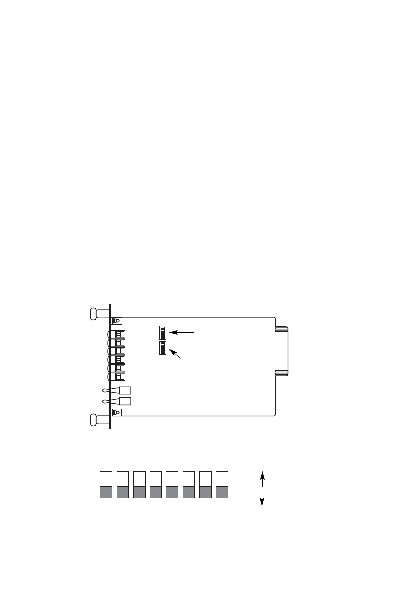
The Model 1140ARC front card has two sets of eight switches (S1 &
S2), which are mounted on the PC board (Figure 1, below). These
configuration switches allow you to configure the Model 1140ARC for a
wide range of applications. The ON/OFF orientation of the DIP
switches is shown in figure 2 (below).
4
Figure 1. Model 1140ARC front card jumper locations
Figure 2. Close-up of DIP switches showing “ON” and “OFF” positions
12345678
ON
OFF
ON
Switch Set 1
(Switch 1:1 on bottom)
SwitchSet 2
(Switch 2:1 on bottom)
Page 6
3.1.1 CONFIGURATION SWITCH SET “S1”
The DIP switches on S1 set data rate, clock source, async./sync.
mode and carrier control method. The default settings are summarized
in the table below. Following the table is a description of all possible S1 switch settings.
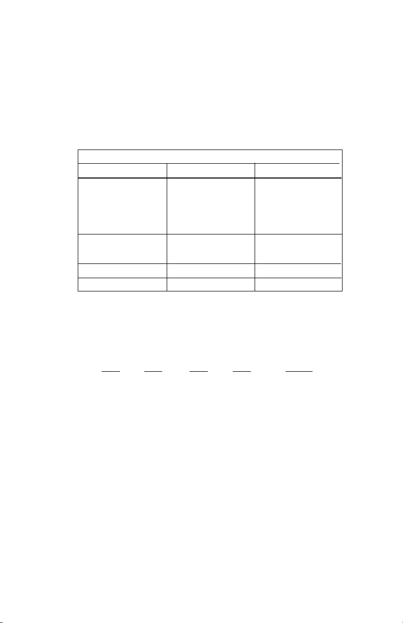
S1-1 through S1-4: Data Rate Setting
Switches S1-1 through S1-4 are set in combination to determine
the asynchronous and synchronous data rate for the Model 1140ARC.
S1-1
S1-2 S1-3 S1-4 Setting
On On On On 1.2 Kbps
Off On On On 1.8 Kbps
On Off On On 2.4 Kbps
Off Off On On 3.6 Kbps
On On Off On 4.8 Kbps
Off On Off On 7.2 Kbps
On Off Off On 9.6 Kbps
Off Off Off On 14.4 Kbps
On On On Off 19.2 Kbps
Off On On Off 28.8 Kbps
On On Off Off 38.4 Kbps
Off On Off Off 57.6 Kbps
5
S1 SUMMARY TABLE
Position Function Factory Default
S1-1 Data Rate On
S1-2 Data Rate Off
S1-3 Data Rate Off
S1-4 Data Rate On
S1-5 Clock Source On
S1-6 Clock Source On
S1-7 Async./Sync. On Async.
S1-8 Carrier Control Off Constantly On
9,600 bps
Internal
}
}
Page 7

S1-5 and S1-6: Clock Source
Switches S1-5 and S1-6 are set in combination to determine the
transmit clock source for the Model 1140ARC.
S1-5
S1-6 Setting
On On Internal transmit clock
Off On Receive recover clock
On Off External transmit clock
S1-7: Asynchronous/Synchronous Mode
The setting for switch S1-7 determines whether the Model
1140ARC is in asynchronous or synchronous operating mode.
S1-7
Setting
On Asynchronous
Off Synchronous
S1-8: Carrier Control Method
The setting for switch S1-8 determines whether the carrier is
“constantly on” or “controlled by R
TS”. This setting allows for operation
in switched carrier, multipoint and/or hardware handshaking
applications.
S1-8
Setting
Off Constantly On
On Switched Carrier
6
Page 8
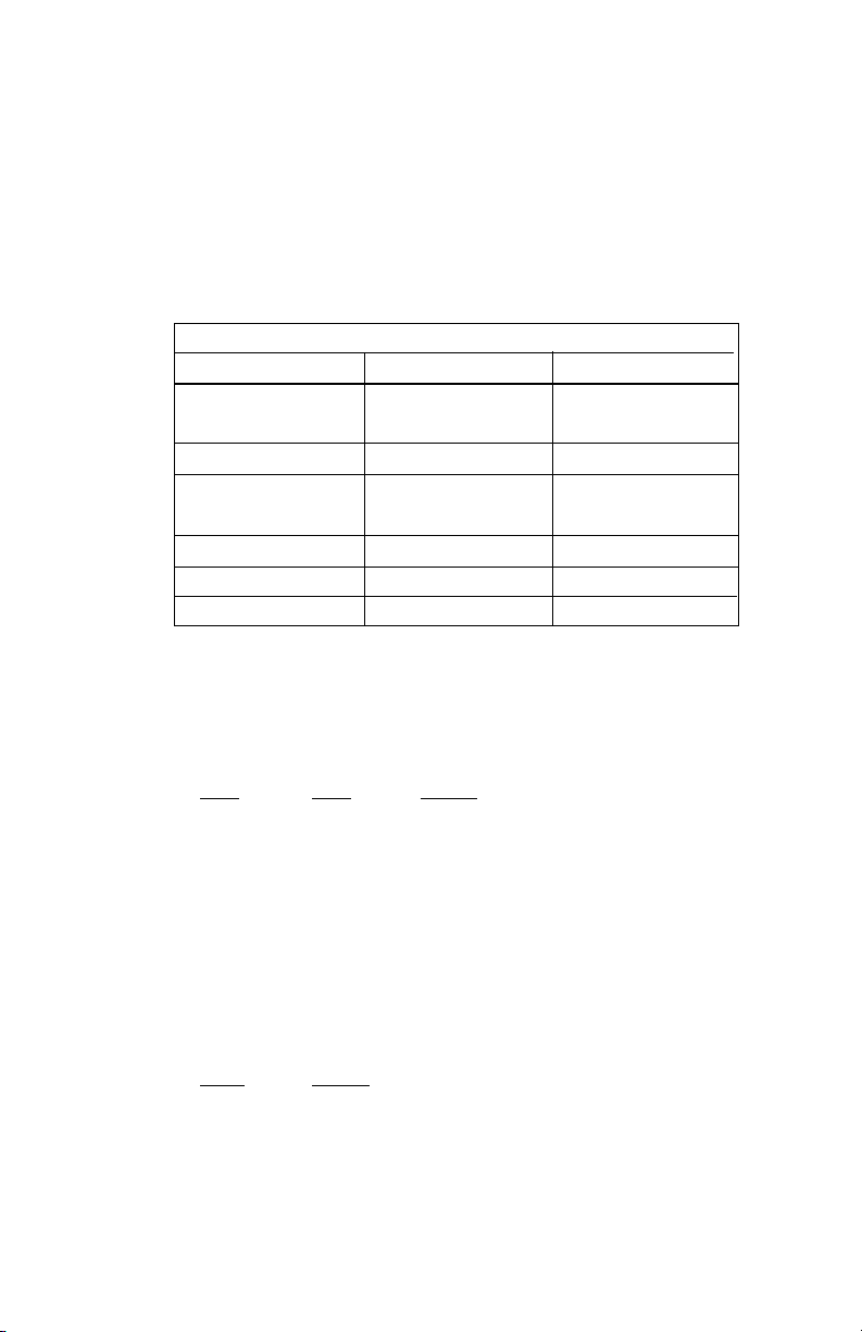
3.1.2 CONFIGURATION SWITCH SET “S2”
The DIP switches on S2 set word length, extended signaling rate,
RTS/CTS delay and V.52 and V.54 diagnostic test. The default settings
are summarized in the table below. Following the table is a description
of all possible S-2 switch settings.
S2-1 and S2-2: Word Length
Switches S2-1 and S2-2 are set in combination to determine the
word length for asynchronous data.
S2-1
S2-2 Setting
Off On 8 bits
On On 9 bits
Off Off 10 bits
On Off 11 bits
S2-3: Extended Signaling Rate
The setting for switch S2-3 determines the range of variability the
Model 1140ARC “looks for” in asynchronous data rates (i.e., the actual
variance from a given frequency level the Model 1140ARC will tolerate).
S2-3
Setting
Off -2.5% to +1% Basic
On -2.5% to +2.3% Extended
7
S2 SUMMARY TABLE
Position Function Factory Default
S2-1 Word Length Off
S2-2 Word Length Off
S2-3
Extended Signaling Rate
Off-2.5% to +2.3%
S2-4 RTS/CTS Delay On
S2-5 RTS/CTS Delay On
S2-6 Future Use -
S2-7 Future Use -
S2-8 V.52/V.54 Tests Off
Enable
}
}
7 mS
10 bits
Page 9

S2-4 and S2-5: RTS/CTS Delay
The combined settings for switches S2-4 and S2-5 determine the
amount of delay between the time the Model 1140ARC “sees” RTS and
when it sends CTS. Options are no delay, 7 ms and 53 ms.
S2-4
S2-5 Setting
On On 7 mS
Off On 53 mS
On Off No delay
Off Off No delay
S2-8: V.54 Loopback Test Enable
To reset the V.54 circuit, set switch S2-6 to the “ON” position, then
back to the “OFF” position..
S2-8
Setting
Off V.54 Enable
On V.54 Disable
3.2 REAR CARD CONFIGURATION
The Model 1140ARC is compatible with two dual-fiber interface
cards, one with dual ST connectors and one with dual SMA connectors.
Both cards use an HD-26 female for the RS-232 interface. The single
configuration jumper (JB1) functions identically on both cards. Figure 3
(below) shows the jumper’s location.
8
Figure 3. Model 1140ARC rear card jumper location
JB1
(pin 1 on right)
3 2 1
Page 10

9
3.2.1 HOW THE JUMPER WORKS
Figure 4 (below) shows the 3-pin jumpers used on the rear card.
The strap enables or disables a particular function depending upon
whether it straddles pins 1 and 2, or pins 2 and 3.
DTE Shield (Pin 1) & FRGND (JB1)
In the connected (closed) position, this strap links DB-25 pin 1 and
frame ground. In the open (disconnected) position, pin 1 is “lifted” from
frame ground.
JB1
Position 1&2 = DTE Shield (Pin 1) and FRGND connected
Position 2&3 = DTE Shield (Pin 1) and FRGND not
connected
Figure 4. Orientation of interface card strap
123 123 123
Page 11

10
4.0 INSTALLATION
This section describes the functions of the Model 1000R16 rack
chassis, tells how to install front and rear Model 1140ARC cards into
the chassis, and provides instructions for connecting the interface
cables.
4.1 THE MODEL 1000R16 RACK CHASSIS
The 1000R16 Rack Chassis (Figure 5, below) has sixteen short
range modem card slots, plus its own power supply. Measuring only
3.5” high, the 1000R16 is designed to occupy only 2U in a 19” rack.
Sturdy front handles allow the 1000R16 to be extracted and transported
conveniently.
4.1.1 THE RACK POWER SUPPLY
The power supply included in the Model 1000R16 rack uses the
same mid-plane architecture as the modem cards. The front card of
the power supply slides in from the front, and the rear card slides in
from the rear. They plug into one another in the middle of the rack.
The front card is then secured by thumb screws and the rear card by
conventional metal screws.
Figure 5. Model 1000R16 rack chassis with power supply
WARNING! There are no user-serviceable parts in the power
supply section of the Model 1140ARC. Voltage setting changes
and fuse replacement should only be performed by qualified
service personnel. Contact Patton Electronics Technical
support at (301) 975-1007, http://www.patton.com, or
support@patton.com for more information.
Page 12

Switching the Power Supply On and Off
The power supply on/off switch is located on the front panel. When
plugged in and switched on, a red front panel LED will glow. Since the
Model 1000R16 is a “hot swappable” rack,
it is not necessary for any
cards to be installed before switching on the power supply
. The power
supply may be switched off at any time without harming the installed
cards.
NOTE: Please refer to the Model 1000RP Series User Manual
AC
and DC Rack Mount Power Supplie
s for fuse and power card
replacement information.
4.2 INSTALLING THE MODEL 1140ARC INTO THE CHASSIS
The Model 1140ARC is comprised of a front card and a rear card.
The two cards meet inside the rack chassis and plug into each other via
mating 50 pin card edge connectors. Use the following steps as a
guideline for installing each Model 1140ARC into the Model 1000R16
rack chassis:
1. Slide the rear card into the back of the chassis along the metal
rails.
2. Secure the rear card using the metal screws provided.
3. Slide the front card into the front of the chassis. It should meet the
rear card when it’s almost all the way into the chassis.
4. Push the front card
gently
into the card-edge receptacle of the rear
card. It should “click” into place.
5. Secure the front card using the thumb screws.
NOTE: Since the Model 1000R16 chassis allows “hot swapping”
of cards, it is
not necessary to power down
the rack when you
install or remove a Model 1140ARC.
11
Page 13

4.3 WIRING UP THE MODEL 1140ARC
Both of the rear interface cards compatible with the Model
1140ARC have one RS-232 port and one dual-connector fiber port (see
Figure 6. below). Depending upon the card you have, the fiber port will
be either an ST or SMA connector. The RS-232 port is always a female
HD-26 connector.
4.3.1 RS-232 CONNECTION
The RS-232 port on the rear card of the Model 1140ARC is wired
as a DCE, and uses a female HD-26 connector. The HD-26 is an
alternate connector according to the EIA RS-232E specification, and
the pin-out is the same as a standard DB-25. Pin 26 is not used.
You will need an interface cable to connect the Model 1140ARC to
your RS-232 device. Assuming your RS-232 device is a DTE (PC,
host, terminal, workstation, etc.), the cable should be wired
straight
through
. You may either provide your own cable, or you may purchase
an HD-26 to DB-25 cable from Patton Electronics Company. Please
call the Patton Sales Department at (301) 975-1000 for price and
delivery information.
12
Dual SMA
Dual ST
Figure 6. Model 1140ARC interface card options
HD-26 F
HD-26 F
Notice! Any terminal cable connected to the Model 1140ARC
must be shielded cable, and the outer shield must be 360
degree bonded–at both ends–to a metal or metalized backshell.
TX
RX
A1
TX
RX
A1
Page 14

4.3.2 FIBER CONNECTIONS
The Model 1140ARC is designed to work with the self-powered
Model 1140A, or with another Model 1140ARC. In either case, you will
need one unit at each end of a dual
fiber cable. This cable connects to
the Model 1140ARC using either ST or SMA connectors. Figure 7
(below) shows a close-up of each of these connector types.
Figure 7. Close up of ST and SMA connections
ST
SMA
alignment pin
faces down
Page 15

5.0 OPERATION
Once you have configured each Model 1140ARC and connected the
cables, you are ready to operate the units. This section describes the
LED status monitors and power-up procedure.
5.1 LED STATUS MONITORS
The Model 1140ARC features ten front panel status LEDs that
indicate the condition of the modem and communication link:
• The green “PWR” LED glows when power is applied to the modem
card through its mid-plane chassis connection.
• The green “TD” and “RD” indicators blink to show positive state
data activity. The Red “TD” and “RD” indicators blink to show
negative state data activity. Solid red indicates an idle state.
• The green “RTS” and “CD” indicators glow solid to show the control
signal is on. The red “RTS” and “CD” indicators glow solid to show
the control signal is off. When the 1140ARC is connected to a
DTE, RTS will glow green for an incoming signal on RS-232 pin 4.
CD will glow green for an incoming signal from the line, and an
outgoing signal on RS-232 pin 8.
• The “Test” LED glows when either the Local Analog Loopback
(LAL) or Remote Digital Loopback (RDL) V.54 test mode is
initiated. The “Error” LED blinks when an error is detected by the
V.52 diagnostics.
5.2 POWER-UP
There is no power switch on the Model 1140ARC: Power is
automatically applied to the 1140ARC when its card-edge connector
makes contact with the chassis’ mid-plane socket, or when the chassis’
power supply is turned on.
Note: The 1140ARC is a “hot swappable”
card—it will not be damaged by plugging it in or removing it while the
rack is powered up.
When the local and remote units are
both
powered up, and are
passing data
normally
, the following LED conditions will exist:
• PWR = green
• TD & RD = flashing red and green
• RTS & CD = green
• Test = off
• Error = off
1413
Page 16

15
5.3 TEST MODES
The Model 1140ARC offers two V.54 test modes and two V.52 test
modes to evaluate the condition of the modems and the communication
link. Both sets of tests can be activated physically from the front panel.
The V.54 test can also be activated from the RS-232 interface.
Note:
V.54 and V.52 test modes on the Model 1140ARC are available for
point-to-point applications only.
5.3.1 LOCAL ANALOG LOOPBACK (LAL)
The Local Analog Loopback (LAL) test checks the operation of the
local Model 1140ARC, and is
performed separately on each unit.
Any
data sent to the local Model 1140ARC in this test mode will be echoed
(returned) back to the user device. For example, characters typed on
the keyboard of a terminal will appear on the terminal screen. To
perform a LAL test, follow these steps:
1. Activate LAL. This may be done in one of two ways: First, by
moving the upper front panel toggle switch RIGHT to “Analog”.
Second, by raising pin 18 on the RS-232 interface (note: be
sure DIP switch S2-8 is off). Once LAL is activated, the Model
1140ARC transmit output is connected to its own receiver.
The “Test” LED should be lit.
2. Verify that the data terminal equipment is operating properly
and can be used for a test.
3. Locate the lower of the two toggle switches on the front panel
of the Model 1140ARC and move it to the right. This will
activate the V.52 BER test mode and inject a “511” test pattern
into the local loop. If any errors are present in the loop, the
red “Error” LED will blink sporadically.
4. If the BER test indicates
no errors
are present, move the V.52
toggle switch to the left, thus activating the “511/E” test with
periodic errors. If the test is working properly, the red “Error”
LED will light. A successful “511/E” test will confirm that the
loop is in place, and that the Model 1140ARC’s built-in “511”
generator and detector are working properly.
5. If the BER test indicates that errors
are
present, check to see
that the RS-232 cable connecting the DTE to the Model
1140ARC is wired straight through, and is plugged in properly.
Also, ensure that the Model 1140ARC is configured properly.
Then re-check your DTE equipment. If you still have errors,
call Patton Technical Support at (301) 975-1007.
Page 17

16
5.3.2 REMOTE DIGITAL LOOPBACK (RDL)
The Remote Digital Loopback (RDL) test checks the performance of
both the local and remote Model 1140ARCs,
and
the communication
link between them. Any characters sent to the remote 1140ARC in this
test mode will be returned back to the originating device. For example,
characters typed on the keyboard of the local terminal will appear on
the local terminal screen
after
having been passed to the remote Model
1140ARC and looped back. To perform an RDL test, follow these
steps:
1. Activate RDL. This may be done in two ways: First, by
moving the upper front panel toggle switch LEFT to “Remote”.
Second, by raising pin 21 on the RS-232 interface. (Note: be
sure DIP switch S2-8 is off).
2. Verify that the DTE equipment on the local end is operating
properly and can be used for a test.
3. Locate the lower of the two toggle switches on the front panel
of the 1140ARC and move it to the right. This will activate the
V.52 BER test mode and inject a “511” test pattern into the
remote loop. If any errors are present in the loop, the red
“Error” LED will blink sporadically.
4. If the BER test indicates
no errors
are present, move the V.52
toggle switch to the left, thus activating the “511/E” test with
periodic errors. If the test is working properly, the red “Error”
LED will light. A successful “511/E” test will confirm that the
loop is in place, and that the Model 1140ARC’s built-in “511”
generator and detector are working properly.
5. If the remote BER test indicates that errors
are
present, and
the local analog loopback/BER tests showed that both Model
1140ARCs were functioning properly, this suggests a problem
with the twisted pair communication line connecting the two
modems. A common problem is improper crossing of the
pairs. Also, verify that the modular connections are pinned
properly, and the twisted pair line has continuity. If you still
have errors, call Technical Support at (301) 975-1007.
Page 18

5.3.3 USING THE V.52 BER TEST INDEPENDENTLY
The Model 1140ARC's V.52 BER test can be used independent of
the V.54 loopback tests. This requires two operators: one to initiate and
monitor the test at both the local and the remote Model 1140ARC. To
use the V.52 BER test by itself, both operators should simultaneously
follow these steps:
1. Locate the lower of the two toggle switches on the front panel
of the Model 1140ARC and move it to the right. This will
activate the V.52 BER test mode and transmit a “511” test
pattern to the other unit. If any errors are present, the
receiving modem’s red “Error” LED will blink sporadically.
Note: For this independent test to function, the “511” switch on
both
Model 1140ARCs must be turned on.
2. If the test indicates no errors are present, move the V.52
toggle switch to the left, thus activating the “511/E” test with
periodic errors present. If the test is working properly, the
receiving modem’s red “Error” LED will blink
regularly
. A
successful “511/E” test will confirm that the link is in place, and
that the Model 1140ARC’s built-in “511” generator and detector
are working properly.
Page 19

APPENDIX A
PATTON MODEL 1140ARC SPECIFICATIONS
Transmission Line: Dual optical cable
Transmission Mode: Asynchronous, half or full duplex, point-to-point
Interfaces: EIA RS-232, CCITT V.24
Data Rates: 0 - 57.6 Kbps
Distance: 4 miles over continuous fiber
RTS/CTS Delay: Switch-selectable: No delay, 7.0 mS, 53 mS
Receiver Sensitivity: -45 dBm
Coupled Power Output: -20 to -25 dBm
Optic Wavelength: 850 nm
LED Indicators: Power, TD, RD, RTS, CD, Test Mode, Error
Connectors: HD-26 female on RS-232 side; ST or SMA connectors
on fiber side
Power Supply: 120/240V (switchable) on rack chassis
Temperature Range: 0-60°C (32-140°F)
Altitude: 0-15,000 feet
Humidity: Up to 95% non-condensing
Weight: 2 oz.
Dimensions: 0.95”W x 3.1”H x 5.4”L
1817
Page 20

APPENDIX B
PATTON MODEL 1140ARC FACTORY REPLACEMENT PARTS
The Patton Model 1140ARC rack system features interchangeable
rear half cards, power cords/fuses for international various operating
environments and other user-replaceable parts. Model numbers and
descriptions for these parts are listed below:
Patton Model #
Description
1000RPEM..........................120/240V Rear Power Entry Module
1000RPSM-2.......................120/240V Front Power Supply Module
1000RPEM-DC ...................DC Rear Power Entry Module
1000RPSM-48A ..................48V Front Power Supply Module
1000RPEM-V ......................120/240V CE Compliant Rear Power
Entry Module
1000RPSM-V ......................120/240V CE Compliant Front Power
Supply Module
0805US ...............................American Power Cord
0805EUR.............................European Power Cord CEE 7
0805UK ...............................United Kingdom Power Cord
0805AUS.............................Australia/New Zealand Power Cord
0805DEN.............................Denmark Power Cord
0805FR ...............................France/Belgium Power Cord
0805IN.................................India Power Cord
0805IS.................................Israel Power Cord
0805JAP..............................Japan Power Cord
0805SW ..............................Switzerland Power Cord
05R16FPB1.........................Single Width Blank Front Panel
05R16FPB4.........................4-Wide Blank Front Panel
05R16RPB1 ........................Single Width Blank Rear Panel
05R16RPB4 ........................4-Wide Blank Rear Panel
0821R4................................400 mA Fuse (5x20mm)
Littlefuse 239.400 or equivalent
0821R2................................200 mA Fuse (5x20mm)
Littlefuse 239.200 or equivalent
056S1..................................Set of 16 #4 pan head screws/washers
19
Page 21

APPENDIX C
PATTON MODEL 1140ARC PIN CONFIGURATIONS
20
8 - (CD) Carrier Detect
7 - (SG) Signal Ground
6 - (DSR) Data Set Ready
5 - (CTS) Clear to Send
4 - (RTS) Request to Send
3 - (RD) Receive Data
2 - (TD) Transmit Data
1 - (FG) Frame Ground
UNIVERSAL D-26 INTERFACE (DCE WIRING)
Digital Loop (RDL) - 21
Data Terminal Ready (DTR) - 20
Analog Loop (LAL) - 18
Receiver Clock (RC - 17
Transmitter Clock (TC) - 15
Page 22

APPENDIX D
BLOCK DIAGRAM
Copyright © 1998
Patton Electronics Company
All Rights Reserved
MODEL 1140ARC
B
LOCK DIAGRAM
21
Page 23

Notes
__________________________________________
__________________________________________
__________________________________________
__________________________________________
__________________________________________
__________________________________________
__________________________________________
__________________________________________
__________________________________________
__________________________________________
__________________________________________
__________________________________________
Page 24

An ISO-9001
Certified Company
Dear Valued Customer,
Thank you for purchasing Patton Electronics products! We do
appreciate your business. I trust that you find this user manual helpful.
We manufacture one of the widest selections of data communications
products in the world including CSU/DSU's, network termination units,
powered and self-powered short range modems, fiber optic modems, interface
converters, baluns, electronic data switches, data-line surge protectors,
multiplexers, transceivers, hubs, print servers and much more. We produce
these products at our Gaithersburg, MD, USA, facility, and can custom
manufacture products for your unique needs.
We would like to hear from you. Please contact us in any of the
following ways to tell us how you like this product and how we can meet your
product needs today and in the future.
Web: http://www.patton.com
Sales E-mail: sales@patton.com
Support E-mail: support@patton.com
Phone - Sales (301) 975-1000
Phone - Support (301) 975-1007
Fax: (301) 869-9293
Mail: Patton Electronics Company
7622 Rickenbacker Drive
Gaithersburg, MD 20879 USA
We are committed to a quality product at a quality price. Patton
Electronics is ISO 9001 certified. We meet and exceed the highest standards
in the industry (CE, UL, etc.).
It is our business to serve you. If you are not satisfied with any
aspect of this product or the service provided from Patton Electronics or its
distributors, please let us know.
Thank you.
Burton A.Patton
Vice President
P.S. Please tell us where you purchased this product:
_________________________________________________________
_________________________________________________________
_________________________________________________________
_________________________________________________________
_________________________________________________________
_________________________________________________________
 Loading...