

Page 1
USER
MANUAL
MODEL 1075
KiloModem II AC
Powered, High-Speed
X.21 Short-Range Modem
CERTIFIED
An ISO-9001
Certified Company
Part #07M1075-B
Doc: 054081U, Rev. C
Revised 1/23/08
SALES OFFICE
(301) 975-1000
TECHNICAL SUPPORT
(301) 975-1007
http://www.patton.com
Page 2

1.0 WARRANTY INFORMATION
Patton Electronics warrants all Model 1075 components to be
free from defects, and will—at our option—repair or replace the product
should it fail within one year from the first date of shipment.
This warranty is limited to defects in workmanship or materials,
and does not cover customer damage, abuse or unauthorized
modification. If this product fails or does not perform as warranted,
your sole recourse shall be repair or replacement as described above.
Under no condition shall Patton Electronics be liable for any damages
incurred by the use of this product. These damages include, but are
not limited to, the following: lost profits, lost savings and incidental or
consequential damages arising from the use of or inability to use this
product. Patton Electronics specifically disclaims all other warranties,
expressed or implied, and the installation or use of this product shall be
deemed an acceptance of these terms by the user.
1.1 RADIO AND TV INTERFERENCE
The Model 1075 generates and uses radio frequency energy, and
if not installed and used properly—that is, in strict accordance with the
manufacturer's instructions—may cause interference to radio and
television reception. The Model 1075 has been tested and found to
comply with the limits for a Class A computing device in accordance
with the specifications in Subpart J of Part 15 of FCC rules, which are
designed to provide reasonable protection from such interference in a
commercial installation. However, there is no guarantee that
interference will not occur in a particular installation. If the Model 1075
does cause interference to radio or television reception, which can be
determined by disconnecting the unit, the user is encouraged to try to
correct the interference by one or more of the following measures:
moving the computing equipment away from the receiver, re-orienting
the receiving antenna and/or plugging the receiving equipment into a
different AC outlet (such that the computing equipment and receiver are
on different branches).
1.2 CE NOTICE
The CE symbol on your Patton Electronics equipment indicates
that it is in compliance with the Electromagnetic Compatibility (EMC)
directive and the Low Voltage Directive (LVD) of the Union European
(EU). A Certificate of Compliance is available by contacting Patton
Technical Support.
1
Page 3

1.3 SERVICE
All warranty and nonwarranty repairs must be returned freight
prepaid and insured to Patton Electronics. All returns must have a
Return Materials Authorization number on the outside of the shipping
container. This number may be obtained from Patton Electronics
Technical Service: (301) 975-1007; http://www.patton.com: or,
support@patton.com.
NOTE: Packages received without an RMA number will not be
accepted.
Patton Electronics' technical staff is also available to answer any
questions that might arise concerning the installation or use of your
Model 1075. Technical Service hours: 8AM to 5PM EST, Monday
through Friday.
2
Page 4

2.0 GENERAL INFORMATION
Thank you for your purchase of this Patton Electronics product.
This product has been thoroughly inspected and tested and is
warranted for One Year parts and labor. If any questions or problems
arise during installation or use of this product, please do not hesitate to
contact Patton Electronics Customer Service at (301) 975-1007.
2.1 FEATURES
• Data rates of 32, 56 and 64 kbps
• Distances to 6 miles (9.7km)
• Switch-selectable carrier control
• Synchronous X.21 operation
• Frequency Shift Keying (FSK) modulation
• DCE/DTE Switchable
• Point-to-point operation over 2 unconditioned twisted pair
• V.54 loopback tests and V.52 compliant BER tests
• 6 LED indicators
• Externally powered
• Transformer isolation
• Silicon Avalanche Diode surge protection
• Made in the U.S.A.
2.2 DESCRIPTION
The Model 1075 KiloModem II X.21 Short Range Modem
supports synchronous data rates of 32, 56 and 64 Kbps. Synchronous
transmit clock options are internal, external and receive recover clock.
Deriving power from a 9V DC wall-mount transformer, the Model 1075
supports extended distances to 6 miles (9.7km) over 2 unconditioned
twisted pairs.
The Model 1075 incorporates two V.54 test modes (local analog
loop and remote digital loop) that are activated by a tiny front panel
switch. In addition, a built-in V.52 Bit Error Test (BER) test generator
that outputs 511 and 511E bit patterns can also be controlled by a
switch on the case. Six LED indicators monitor transmit data, receive
data, control, indication, test mode (TM) and Error Status (ER). For
protection against ground loops and transient surges, the Model 1075
incorporates both isolation transformers and Silicon Avalanche Diode
surge suppressors.
Housed in a miniature ABS plastic case, the Model 1075 comes
equipped with a female DB-15 connector and a choice of twisted pair
interfaces (RJ-11 jack or RJ-45 jack).
3
Page 5
3.0 CONFIGURATION
The Model 1075 is easy to install and is ruggedly designed for
excellent reliability. The following instructions will help you to properly
configure the Model 1075.
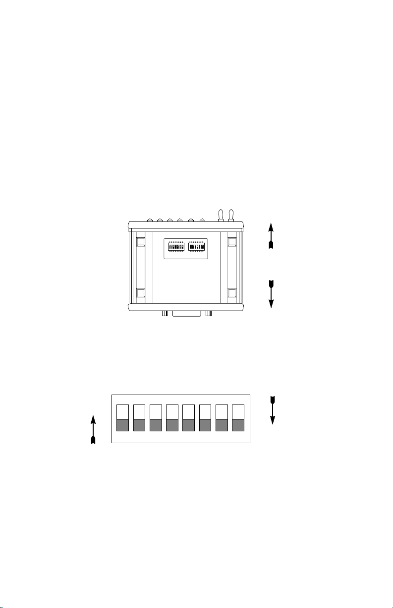
3.1 CONFIGURATION SWITCHES
The Model 1075 uses a unique set of 16 external mini DIP
switches that allow configuration to wide range of applications. The 16
external switches are grouped into two eight-switch sets, and are
externally accessible from the underside of the Model 1075 (See Figure
1).
12345678ON12345678
ON
S1 S2
Front
Rear
Figure 1. Underside of the 1075 Showing Location of DIP Switches
The two sets of DIP switches on the underside of the Model 1075
will be referred to as S1, S2. Figure 2 shows the orientation of DIP
Switches S1 and S2 with respect to “ON” and “OFF” positions.
ON
Figure 2. Close-up of DIP Switches Showing “ON” / “OFF” Positions
ON
12345678
OFF
4
Page 6
3.1.1 Configuration Switch Set “S1”
The switches on Switch S1 set V.54 Test Functions. Default
settings and detailed descriptions for each switch are shown below.
S1 SUMMARY TABLE
Position Function Factory Default
S1-1 thru S1-7 Not Assigned Off
S1-8 V.54 Test Functions Off Enabled
Switches S1-1 through S1-7: Not Assigned
Switch S1-8: V.54 Test Functions
Switch S1-8 enables or disables the Model 1075 V.54 loopback
test modes.
S1-8
Off Enabled V.54 test functions enabled
On Disabled V.54 test functions disabled
3.1.2 Configuration Switch Set “S2”
The switches on Switch S2 set data rates, clock source, carrier
control and front panel switch operation. Default settings and detailed
descriptions for each switch are shown below.
Position Function Factory Default
S2-1 Data Rate On
S2-2 Data Rate Off
S2-3 Clock Mode On
S2-4 Clock Mode On
S2-5 Carrier Control Off Forced On
S2-6 Not Assigned Off
S2-7 Not Assigned Off
S2-8 Front Panel Switches On Enabled
Activation Description
S2 SUMMARY TABLE
}
}
56 kbps
Internal
5
Page 7

Switches S2-1 and S2-2: Data Rate
Switches S2-1 and S2-2 are set in combination to determine the
synchronous data rate for the Model 1075.
S2-1
S2-2 Setting
Off On 32 kbps
On Off 56 kbps
On On 64 kbps
Switches S2-3 and S2-4: System Clock Mode
The setting for switches S2-3 and S2-4 determines the transmitter
clocking mode for the Model 1075.
S2-3
S2-4 Clock Mode Description
On On Internal System clock
generated internally
On Off External (DTE) System clock derived
from terminal interface
Off On Receive Recover System clock derived
from the received line
signal.
Switch S2-5: Carrier Control
S2-5
Carrier Description
Off Always On Transmitter is always ON
On Follows terminal Transmitter controlled by “Control”
signal from X.21DTE (or by
“Indication” signal from X.21 DCE)
Switches S2-6 and S2-7: Not Assigned
Switch S2-8: Front Panel Switch Enable/Disable
Switch S2-8 determines whether the front panel switches may be
used to perform diagnostic functions.
S2-8
Activation Description
On Enabled Front panel switches may be used
to activate/terminate diagnostics.
Off Disabled Front panel switches will have no
effect on operation of the unit.
6
Page 8
3.2 CONFIGURATION STRAPS
In addition to the configuration switches described above, the
Model 1075 is also equipped with two internal straps that set the
DTE/DCE Configuration and the DB-15 Shield. In order to configure
these straps, you must open the Model 1075 case.
NOTE: Before opening the case, determine whether the default
settings are correct for your application (see Sections 3.2.3 and
3.2.4)
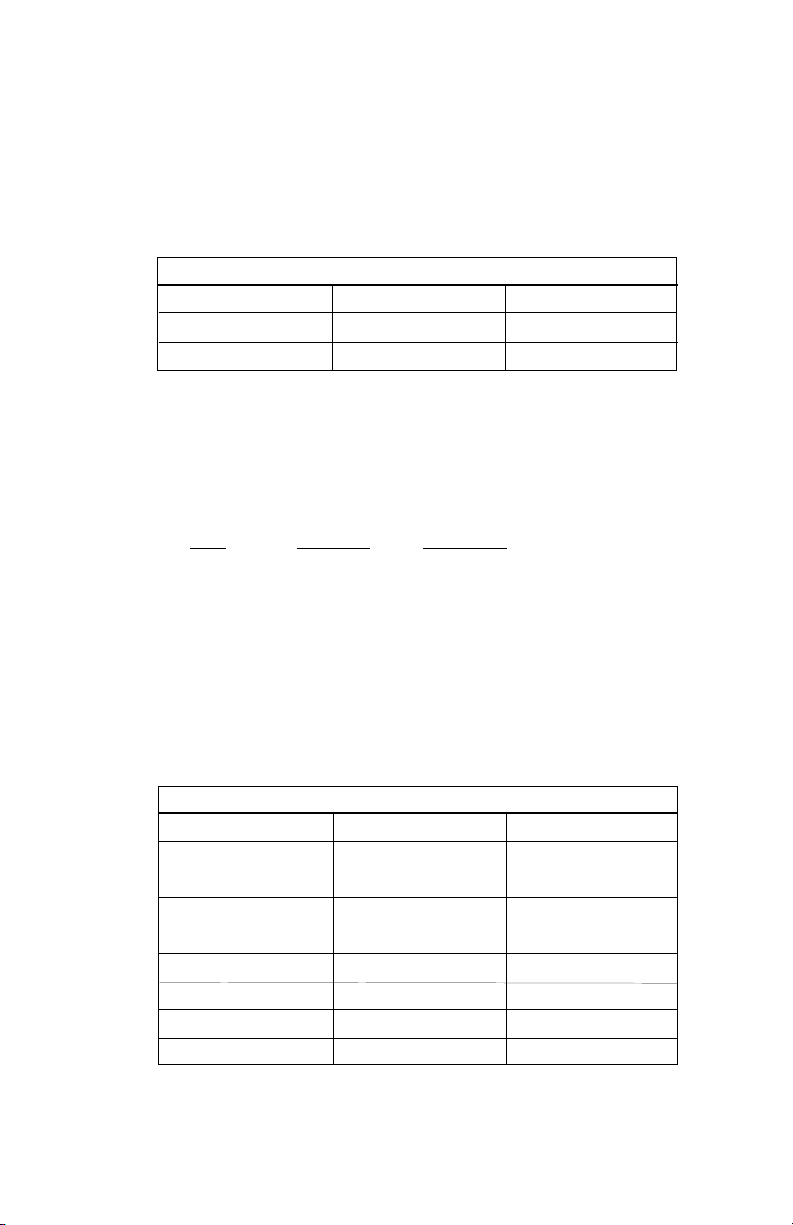
3.2.1 Opening the Case
To open the Model 1075 insert a flat head screw driver into an
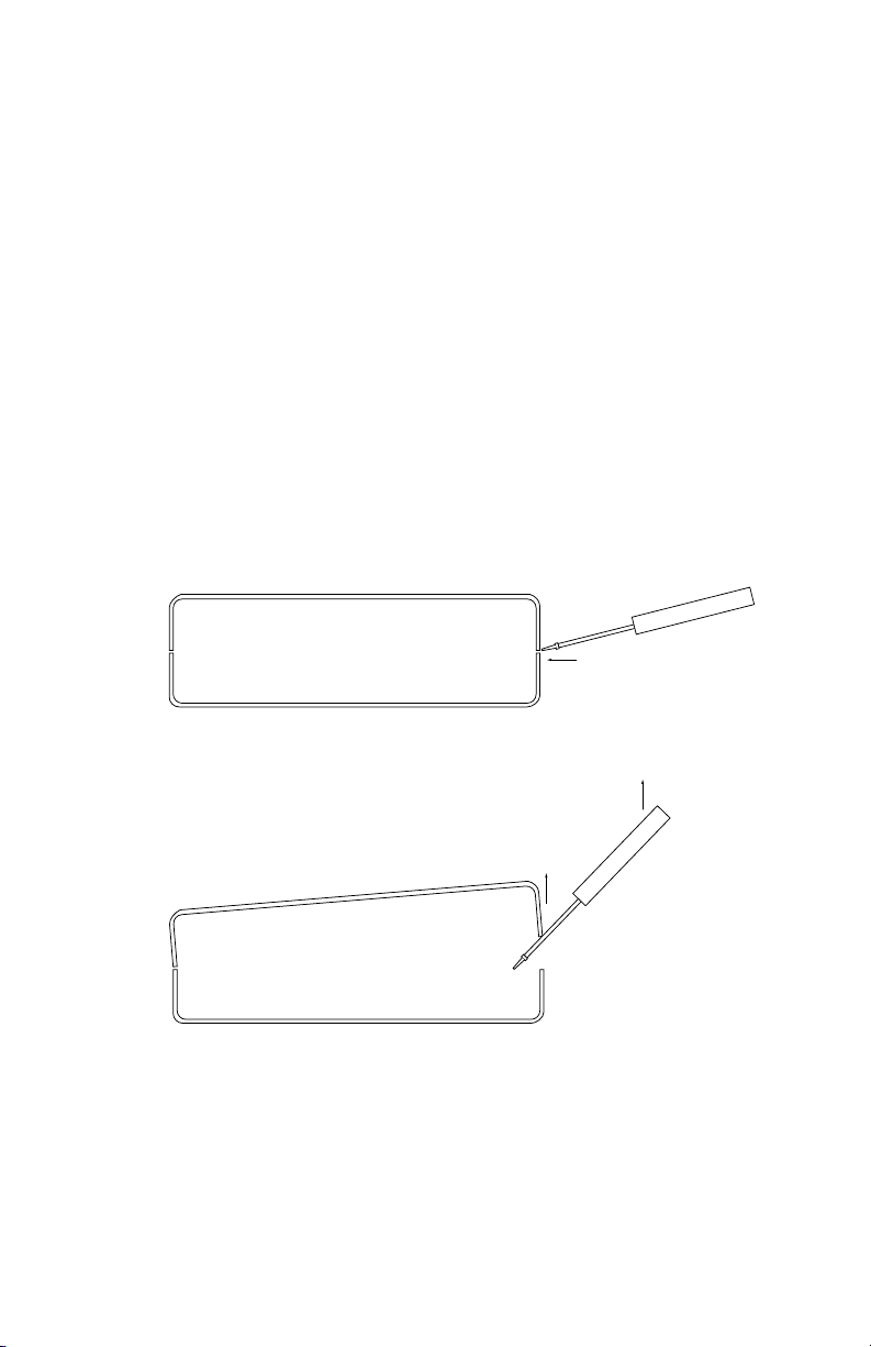
open slot on either side of the case, as in Figure 3. Twist the screw
driver head slightly and the top half of the case will separate from the
lower half, as in Figure 4, below.
Figure 3. Opening the 1075 Case with a Small Screwdriver
Figure 4. Opening the 1075 Case With a Small Screwdriver
To close the case, fit the 2 halves together snugly and snap them
back in place.
7 8
Page 9

3.2.2 Location of the Internal Straps
Figure 5 (below) shows the location of the DCE/DTE switch and the
JP1 strap on top side of the the PC board.
JP1 Strap
Front
DTE
DTE/DCE Strap
Figure 5 . Position of DTE/DCE and JP1 Jumper Straps on Model 1075 PC Board
DCE
Rear
3.2.3 Setting the DCE/DTE Strap
The X.21 interface on the Model 1075 is DCE/DTE switchable.
The default setting is DCE, based upon how the Model 1075 sees its
own
orientation. When configured this way, the Model 1075 will want to
connect to an X.21 DTE
enable the Model 1075 to connect to an X.21 DCE
device. Re-positioning the DCE/DTE strap will
device (See Figure
6, below).
DTE
DCE
Figure 6 . Close-Up of Model 1075 PC Board With Close-up of DCE/DTE Strap
Default Setting = “DCE”
The X.21 DCE/DTE strap is located near the DB-15 connector on
the PC board. The arrows on the top of the strap indicate the
configuration of the Model 1075. For example, if the DCE arrows are
pointing toward the DB-15 Connector, the Model 1075 is configured as
a “DCE” and must connect to an X.21 DTE device.
To change the DCE/DTE orientation of the Model 1075 X.21
interface, simply remove the strap and rotate it 180
o
so the appropriate
arrows are pointing toward the DB-15 Connector.
Page 10

3.2.4 Setting the JP1 Shield Strap
The setting of JP1 determines whether the shield (pin 1) of the
X.21 interface is connected signal ground. In the default setting, DB-15
shield is connected to signal ground. The X.21 shield is not connected
to signal ground when the jumper is placed on pins 1 and 2 . See
Figure 7, below.
1
Front
2
Rear
3
Figure 7. Jumper JP1 Orientation on the PC board
Jumper 1: DB15 Shield
Position
1-2
2-3 Connected to signal ground
DB15 Shield
Not connected to signal ground
(default)
9
Page 11

4.0 INSTALLATION
When you have properly configured the configuration switches and
straps, you are ready to connect the Model 1075 to connect to your
system. This section tells you how to properly connect the Model 1075
to the twisted pair.
4.1 CONNECTION TO THE TWISTED PAIR INTERFACE
The Model 1075 supports full or half duplex communication
between two X.21 devices at distances to 6 miles (9.7 km) and data
rates to 64 kbps. There are two essential requirements for installing
the Model 1075:
1. These units work in pairs. Therefore, you must have one
Model 1075 (or compatible unit) at each end of a two twisted
pair interface.
2. To function properly, the Model 1075 needs two twisted pairs
of metallic wire. These pairs must be unconditioned, dry
metallic wire, between 19 and 26 AWG (the higher number
gauges may limit distance somewhat). Standard dial-up
telephone circuits, or leased circuits that run through signal
equalization equipment, are not acceptable.
For your convenience, the Model 1075 is available with two
different twisted pair interface options: RJ-11 jack or RJ-45 jack.
4.1.1 Twisted Pair Connection Using RJ-11 OR RJ-45
The RJ-11 and RJ-45 connectors on the Model 1075's twisted pair
interface are pre-wired for a standard TELCO wiring environment. The
signal/pin relationships are shown below.
RJ-1
1 SIGNAL RJ-45 SIGNAL
1...................GND 1 .................N/C
2...................RCV 2 .................GND
3...................XMT 3 .................RCV
4...................XMT 4 .................XMT
5...................RCV 5 .................XMT
6...................GND 6 .................RCV
7 .................GND
8 .................N/C
10
Page 12

When connecting two Model 1075s, it is necessary to use a "crossover" cable. The diagram below shows how a cross-over cable should
be constructed for an environment where both Model 1075s use a 8wire RJ-45 connector. Similar logic should be followed when using RJ11 connectors or a combination of the two.
RJ-45 Cable (8-W
ire)
SIGNAL PIN# PIN# SIGNAL
N/C 1 1 N/C
†
GND
2-----------------------7 GND
RCV 3-----------------------5 XMT
XMT 4-----------------------6 RCV
XMT 5-----------------------3 RCV
RCV 6-----------------------4 XMT
†
GND
7-----------------------2 GND
N/C 8 8 N/C
†
Connection to ground is optional
1
2
3
4
5
6
Figure 8. Pin Number Assignments for RJ11 and RJ45 Modular Jacks
4.2 CONNECTION TO X.21 INTERFACE
†
†
1
2
3
4
5
6
7
8
To connect the Model 1075 to a piece of data terminal or data
communications hardware, use a
straight through
DB-15 cable. Plug
the cable directly into the DB-25 port on the rear of the Model 1060.
If it is necessary to construct a special interface cable, please refer to
the pinout diagrams in Appendix C.
Notice! Any terminal cable connected to the Model 1075
must be shielded cable, and the outer shield must be 360
degree bonded–at both ends–to a metal or metalized backshell.
11
Page 13

4.3 AC POWER CONNECTIONS
Power is supplied to the Model 1075 by a 9 VDC, 1 A wall mount
transformer. This transformer connects to the Model 1075 by means of
a cannon jack on the rear panel. The Model 1075 is powered-up as
soon as it is plugged into an AC outlet–there is no power switch.
120 VAC Power (US)
The 120 VAC adapter supplied with the standard version of the
Model 1075 is a “wall mount” type, and may be plugged into any
approved 120 VAC wall plug.
230 VAC Power (IEC)
The 230 VAC adapter supplied with the international version of the
Model 1075 is equipped with an IEC-320 shrouded male connector.
This connects with one of several available country-specific power
cords (see the ordering information in Appendix C.) You may
purchase these power cords from Patton Electronics at: (301) 975-
1007; http://www.patton.com; or, support@patton.com; or from a
local vendor.
12
Page 14

5.0 OPERATION
Once the Model 1075 is properly configured and installed, it should
operate transparently—as if it were a standard cable connection.
Section 5.0 describes the LED status monitors and the built-in V.52 and
V.54 test modes. The Model 1075 is powered by a 9V DC external wall
mount transformer. To power up the unit, connect the power supply
cord to the power jack on the rear of the Model 1075 and plug the
power adapter into the wall. There is no ON/OFF switch.
5.1 LED STATUS MONITORS
The Model 1075 features six front panel LEDs that indicate the
status of the unit and the communication link. Figure 9 shows the front
panel location of each LED. Following Figure 9 is a description of each
LEDs function.
Model 1075
(Control) (Ind)
RDTD RTS CD Error Test
Figure 9 - Front Panel of the Patton Model 1075
KiloModem-II
511 -
511E -
56/64K Baseband Modem
V.54 Test
Modes
- Remote
- Normal
- Local
TD (Transmit Data) Glows red to indicate an idle condition
or binary 1 data. Glows green to indicate an active
condition or binary 0 data. Glows orange to indicate
rapidly changing data. Source: DTE.
RD (Receive Data) Glows red to indicate an idle condition
or binary 1 data. Glows green to indicate an active
condition or binary 0 data. Glows orange to indicate
rapidly changing data. Source: DCE.
Control Glows green to indicate that Control from DTE is active.
Red indicates that Control from the DTE is inactive.
Indication Glows green to indicate that the Indication from DCE is
active. Red indicates that the Indication from the DCE
is inactive.
Error Glows red when errors are detected during the 511 or
511/E BER tests.
Test Glows red when the V.54 loopback test or V.52 BER
tests are initiated.
13
Page 15

5.2 TEST MODES
The Model 1075 offers two V.54 test modes to evaluate the
condition of the modems and the communication link. These tests are
activated from the front panel.
5.2.1 Local Analog Loopback (LAL)
The Local Analog Loopback (LAL) test checks the operation of the
local Model 1075, and is performed separately on each unit. Any data
sent to the local Model 1075 in this test mode will be echoed (returned)
back to the user device. For example, characters typed on the
keyboard of a terminal will appear on the terminal screen. To perform a
LAL test, follow these steps.
A. Activate LAL. This may by moving the front panel toggle
switch DOWN to LAL. Once LAL is activated, the Model 1075
transmitter output is connected to its own receiver. The test
LED should be lit.
B. Verify that the data terminal equipment is operating properly
and can be used for a test. If a fault is indicated, call a
technician or replace the unit.
C. Perform a Bit Error Rate (BER) test on each unit. If the BER
test equipment indicates no faults, but the data terminal
indicates a fault, follow the manufacturer’s checkout
procedures for the data terminal. Also, check the interface
cable between the terminal and the Model 1075.
5.2.2 Remote Digital Loopback (RDL)
The RDL test checks the performance of both the local and remote
Model 1075, and the communication link between them. Any
characters sent to the remote Model 1075 in this test mode will be
returned back to the originating device. For example, characters typed
on the keyboard of the local terminal will appear on the local terminal
screen after having been passed to the remote Model 1075 and looped
back. To perform an RDL test, follow these steps:
A. Activate RDL by moving the front panel toggle switch UP to
RDL.
B. Perform a BER test on the system.
(cont)
14
Page 16

C. If the BER test equipment indicates a fault, and the Local
Analog Loopback test was successful for both Model 1075s,
you may have a problem with the twisted pair line between the
modems. You should then check the twisted pair line for
proper connections and continuity.
5.2.3 How to Use the V.52 BER Test Independently
The V.52 BER test can be used independently of the V.54 loopback
tests. This requires two operators: one to initiate and monitor the test
at the local Model 1075, and one at the remote Model 1075. To use the
V.52 BER test by itself, both operators should simultaneously follow
these steps:
1. Locate the 511/511E toggle switch on the front panel of the
1075 and move it UP. This activates the V.52 BER test mode
and transmits a 511 test pattern to the other unit. If any errors
are present, the receiving modem’s red Error LED will blink
sporadically. For this test to work, make sure the 511 switch
on both Model 1075s is on.
2. If the test indicates no errors are present, move the V.52
toggle switch DOWN, activating the 511/E test with errors
present. If the test is working properly, the receiving modem's
red Error LED will blink regularly. A successful 511/E test will
confirm that the link is in place, and that the Model 1075’s
built in 511 generator and detector are working properly.
5.3 POWER-DOWN
There is no power switch on the Model 1075. You turn it off by
unplugging the AC power adapter from the wall.
15 16
Page 17

APPENDIX A
PATTON MODEL 1075 SPECIFICATIONS
Approvals: CE European Directives
DTE/DCE I/F: X.21 DB15F DCE or DTE, EIA RS-422
Compliant
Compatibility: 1035, 1045 , 1075, 1080A, 1090 series units
Transmission
Format: Synchronous
Transmission Unconditioned twisted pair 19 - 26 AWG
Line Interface: Externally accessible RJ-45 (RJ-11
Optional)
Clock Internal, External and Network (Receive
Recover)
Distance: Up to 6 miles (9.7km)
Interfaces: CCITT/ITU X.21
Data Rates: 32, 56 and 64 Kbps (switch selectable)
Isolation: 1500V RMS via isolation transformers
Surge Protection: IEC-801-S, Level 2, 1kV
Carrier Control Constantly on or Controlled by “Control”
from DTE device (DCE mode) or
“Indication” from DCE device (DTE mode)
Connectors: DB-15 female
RJ-11 or RJ-45 on line side
Power Supply: 9V DC wall-mount transformer, 200mA
Temperature
Range: 0-60°C (32-140°F)
Altitude: 0-15,000 feet
Humidity: 5 to 95% noncondensing
Dimensions: 1.54H x4.1”W x 3.7”D
Power Options: 120 VAC 50/60Hz, external transformer;
230 VAC 50/60Hz, external transformer
Weight: 2.5 lbs. (1.1 Kg)
Page 18

APPENDIX B
MODEL 1075 FACTORY REPLACEMENT
PARTS AND ACCESSORIES
Patton Model #
Description
1075 ................................KiloModem II X.21 Short Range Modem
0805B..............................120V Wall Mount AC Adapter
08059DCI ........................230V AC Adapter (No Power Cord)
0805US ...........................American Power Cord
0805EUR.........................European Power Cord CEE 7
0805UK ...........................United Kingdom Power Cord
0805AUS.........................Australia/New Zealand Power Cord
0805DEN.........................Denmark Power Cord
0805FR............................France/Belgium Power Cord
0805IN.............................India Power Cord
0805IS.............................Israel Power Cord
0805JAP..........................Japan Power Cord
0805SW...........................Switzerland Power Cord
17 18
Page 19

APPENDIX C
MODEL 1075 X.21 Interface
DB15 Female
Pin Signal Source
1 Shield 2 Transmit (a) DTE
3 Control (a) DTE
4 Receive (a) DCE
5 Indication (a) DCE
6 System Clock (a) DCE
7- 8 Signal Ground 9 Transmit (b) DTE
10 Control (b) DTE
11 Receive (b) DCE
12 Indication (b) DCE
13 System Clock (b) DCE
14 - 15 - -
Page 20

APPENDIX D
MODEL 1075 PIN CONFIGURATIONS
BLOCK DIAGRAM
Copyright ©
Patton Electronics Company
All Rights Reserved
19
Page 21

Page 22

Page 23

Page 24

Dear Valued Customer,
Thank you for purchasing Patton Electronics products! We do
appreciate your business. I trust that you find this user manual helpful.
We manufacture one of the widest selections of data communications
products in the world including CSU/DSU's, network termination units,
powered and self-powered short range modems, fiber optic modems, interface
converters, baluns, electronic data switches, data-line surge protectors,
multiplexers, transceivers, hubs, print servers and much more. We produce
these products at our Gaithersburg, MD, USA, facility, and can custom
manufacture products for your unique needs.
We would like to hear from you. Please contact us in any of the
following ways to tell us how you like this product and how we can meet your
product needs today and in the future.
Web: http://www.patton.com
Sales E-mail: sales@patton.com
Support E-mail: support@patton.com
Phone - Sales (301) 975-1000
Phone - Support (301) 975-1007
Fax: (301) 869-9293
Mail: Patton Electronics Company
7622 Rickenbacker Drive
Gaithersburg, MD 20879 USA
We are committed to a quality product at a quality price. Patton
Electronics is ISO 9001 certified. We meet and exceed the highest
standards in the industry (CE, UL, etc.).
It is our business to serve you. If you are not satisfied with any
aspect of this product or the service provided from Patton Electronics or its
distributors, please let us know.
Thank you.
Burton A.Patton
Vice President
P.S. Please tell us where you purchased this product:
 Loading...