

Patton electronic 1070RC User Manual
USER
MANUAL
MODEL 1070RC
AC Powered, Synchronous
Short Range Modem:
Rack Mount Card
CERTIFIED
An ISO-9001
Certified Company
Part #07M1070RC-B
Doc #067021U
Revised 1/23/08
, Rev. C
SALES OFFICE
(301) 975-1000
TECHNICAL SUPPORT
(301) 975-1007
http;//www.patton.com

1.0 WARRANTY INFORMATION
Patton Electronics warrants all Model 1070RC components to be
free from defects, and will—at our option—repair or replace the product
should it fail within one year from the first date of shipment.
This warranty is limited to defects in workmanship or materials, and
does not cover customer damage, abuse or unauthorized modification.
If this product fails or does not perform as warranted, your sole
recourse shall be repair or replacement as described above. Under no
condition shall Patton Electronics be liable for any damages incurred
by the use of this product. These damages include, but are not limited
to, the following: lost profits, lost savings and incidental or
consequential damages arising from the use of or inability to use this
product. Patton Electronics specifically disclaims all other warranties,
expressed or implied, and the installation or use of this product shall be
deemed an acceptance of these terms by the user.
1.1 RADIO AND TV INTERFERENCE
The Model 1070RC generates and uses radio frequency energy,
and if not installed and used properly—that is, in strict accordance with
the manufacturer's instructions—may cause interference to radio and
television reception. The Model 1070RC has been tested and found to
comply with the limits for a Class A computing device in accordance
with the specifications in Subpart J of Part 15 of FCC rules, which are
designed to provide reasonable protection from such interference in a
commercial installation. However, there is no guarantee that
interference will not occur in a particular installation. If the Model
1070RC does cause interference to radio or television reception, which
can be determined by turning the power off or removing the card, the
user is encouraged to try to correct the interference by one or more of
the following measures: moving the computing equipment away from
the receiver, re-orienting the receiving antenna and/or plugging the
receiving equipment into a different AC outlet (such that the computing
equipment and receiver are on different branches). In the event the
user detects intermittent or continuous product malfunction due to
nearby high power transmitting radio frequency equipment, the user is
strongly advised to take the following steps: use only data cables with
an external outer shield bonded to a metal or metalized connector; and,
configure the rear card as shown in section 3.3 of this manual.
1.2 CE NOTICE
The CE symbol on your Patton Electronics equipment indicates
that it is in compliance with the Electromagnetic Compatibility (EMC)
directive and the Low Voltage Directive (LVD) of the Union European
(EU). A Certificate of Compliance is available by contacting Technical
Support.
1

1.3 SERVICE
All warranty and nonwarranty repairs must be returned freight
prepaid and insured to Patton Electronics. All returns must have a
Return Materials Authorization number on the outside of the shipping
container. This number may be obtained from Patton Electronics
Technical Support: (301) 975-1007; http://www.patton.com; or,
support@patton.com.
NOTE: Packages received without an RMA number will not be
accepted.
Patton Electronics' technical staff is also available to answer any
questions that might arise concerning the installation or use of your
Model 1070RC. Technical Service hours: 8AM to 5PM EST, Monday
through Friday.
2

2.0 GENERAL INFORMATION
Thank you for your purchase of this Patton Electronics product.
This product has been thoroughly inspected and tested and is
warranted for One Year parts and labor. If any questions during
installation or use of the 1070RC, contact Patton Electronics Technical
Support at: (301) 975-1007.
2.1 FEATURES
• Data Rates from 1200 to 19,200 bps, switch selectable
• Optical Isolation
• High Speed Surge Protection
• Supports distances up to 10 miles
• Mounts in Patton's 16-Card Rack Chassis
• Bi-state LED indicators
• Point-to-Point or Multipoint
• Loopback Test Modes
• Internal or External Clocking
• Hardware and Software Flow Control Support
• Made in the U.S.A.
2.2 DESCRIPTION
The Model 1070RC Synchronous Short Range Modem Rack
Card operates full duplex, over two unconditioned twisted pair.
Supporting data rates to 19.2 Kbps, the Model 1070RC has a maximum
range of 10 miles (@ 1200 bps over 19 AWG wire). The Model
1070RC passes one control signal in each direction, and features both
optical isolation and Silicon Avalanche Diode surge protection on the
data lines side. Clocking can be sourced internally or externally.
The Model 1070RC is designed to mount in Patton's 2U high 19"
rack chassis. This 16 card chassis has a switchable 120/240 volt
power supply and mounts cards in a mid-plane architecture: The front
"brains" half-card can be plugged into different rear "interface" cards.
This means that the 1070RC card can have several interface options,
and can be switched with other Patton short haul cards.
The Model 1070RC has two built-in diagnostic tools: local and
remote loopback test. Additionally, bi-level LEDs on the 1070RC's
front panel allow you to visually monitor communication.
3
3.0 CONFIGURATION
This section describes the location and orientation of the Model
1070RC's configuration switches, provides detailed instructions on
setting each switch, and describes strap settings for each of the rear
connection cards.
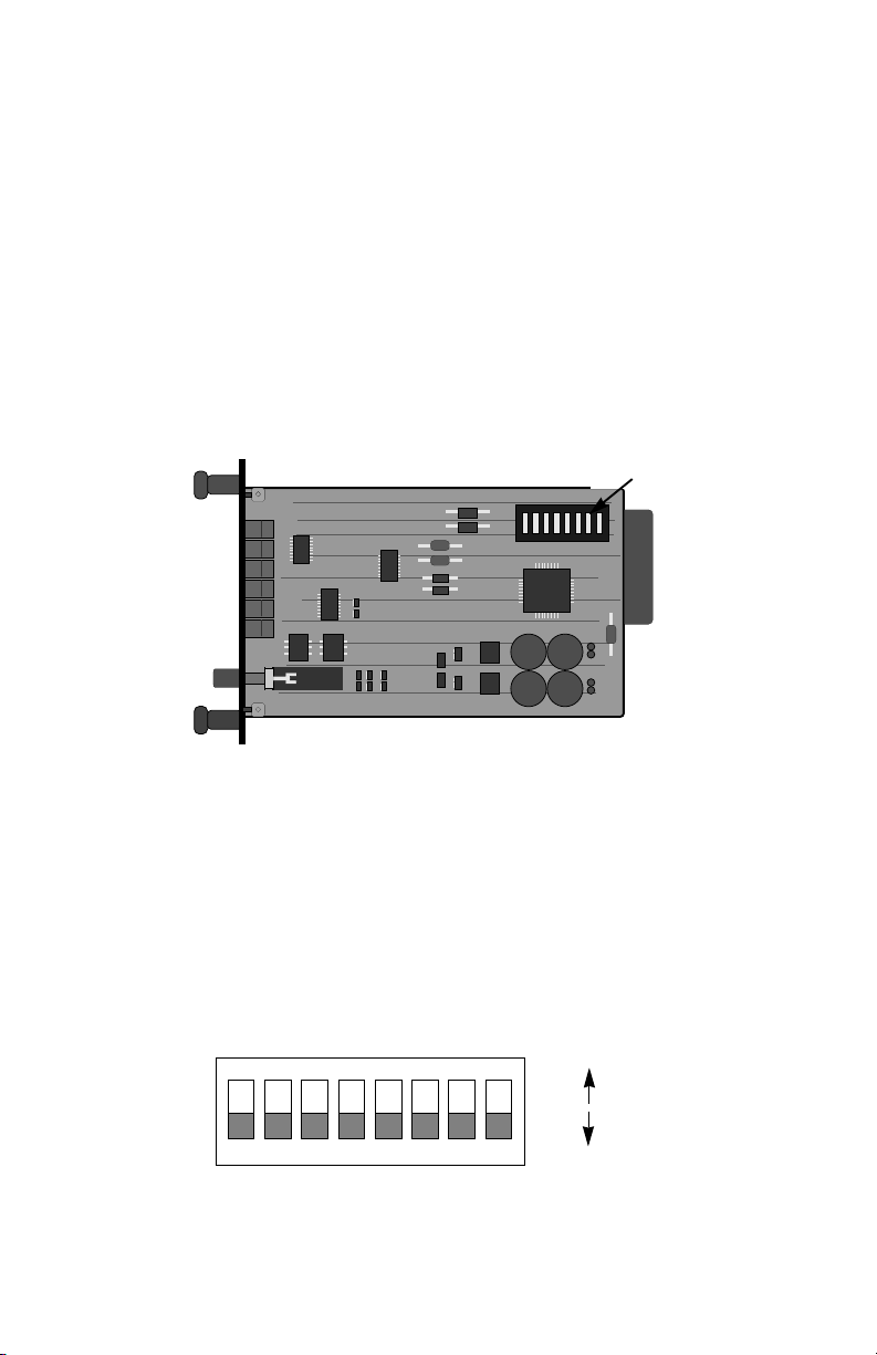
The Model 1070RC uses a set of eight DIP switches that allow
configuration to a wide range of synchronous applications. These DIP
switches are accessible when the card is slid out of the rack chassis.
Once configured, the Model 1070RC is designed to operate
transparently, without need for frequent re-configuration.
SW1
(SW1-1 on left)
Figure 1. Model 1070RC Board Showing Location of DIP Switches
3.1 SWITCH LOCATIONS AND ORIENTATION
The eight DIP switches on the Model 1070RC board allow you to
specify data rate, clocking method, RTS/CTS delay, and carrier control
method. Figure 2 (below) shows the orientation of the DIP switches
with respect to "ON" and "OFF" positions. The table on the following
page summarizes the switch settings, including the factory default
settings.
ON
ON
12345678
Figure 2. Close Up of DIP Switches Showing ON/OFF Positions.
4
OFF

SWITCH SUMMARY TABLE
Position Function Factory Default
Switch 1 Data Rate Off
Switch 2 Data Rate Off
Switch 3 Data Rate On
Switch 4 Not Used N/A
Switch 5 Transmit Clock Off
Switch 6 RTS/CTS Delay On
Switch 7 RTS/CTS Delay Off
Switch 8 Carrier Control Off
3.2 DETAILED SWITCH SETTINGS
The following section provides detailed information about the
function of each DIP switch, and lists all possible settings. Use this
section as configuration guide for applications where the 1070RC's
default would not provide correct results.
Data Rate
Switches 1 thru 3 are set in combination to allow the Model
1070RC to be used at data rates from 1200 bps up to 19,200 bps.
}
}
Constant
9,600 Bps
8 ms
Switch 1
On On On 1.2 Kbps
Off On On 2.4 Kbps
On Off On 4.8 Kbps
On On Off 7.2 Kbps
Off Off On 9.6 Kbps
Off On Off 14.4 Kbps
On Off Off 19.2 Kbps
Off Off Off 19.2 Kbps
Note: Switch 4 is not used.
Switch 2 Switch 3 Setting
5

Transmit Clock
Switch 5 is used to specify the clocking method. The Model
1070RC can provide an internal clock (Pin 15),or receive an external
clock (from Pin 24).
Switch 5
On = Internal
Off = External
RTS/CTS Delay
Switches 6 and 7 are used together to specify RTS/CTS delay.
After request to send (RTS) is raised by the host terminal, the 1070RC
raises CTS after a slight delay in order to give the remote terminal time
to receive an incoming signal. Depending on the type of environment,
either a 0 mS, 8 mS or 53 mS delay can be selected.
Switch 6
Switch 7
On On = 0 mS
On Off = 8 mS
Off Off = 53 mS
Carrier Enable
Switch 8 is used to specify how the carrier signal is raised. In most
point-to-point , full duplex applications, the carrier signal can remain
constantly "high". Important Note: In a multi-point environment, set
the host to "Constant Carrier" and each slave to "Controlled by RTS".
Switch 8
On = Controlled by RTS
Off = Constant Carrier
6
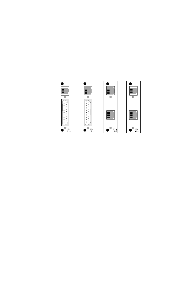
3.3 REAR CARD CONFIGURATION
The 1070RC has four interface half-card options: DB-25/RJ-11,
DB-25/RJ-45, RJ-45/RJ-11, and dual RJ-45. Each of these options
supports one RS-232 connection and one 4-wire connection. Figure 4
(opposite page) illustrates the four different interface options for the
Model 1070RC:
RJ-11 (6-wire)
RJ-45 (8-wire) RJ-45 (8-wire) RJ-11 (6-wire)
DB-25 F
Figure 4. Model 1070RC interface half-card options
DB-25 F
RJ-45 (10-wIre)
RJ-45 (10-wire)
Prior to installation, you will need to examine the rear half-card you
have selected and be sure it is configured properly for your application.
Each rear half-card is configured by setting straps located on the PC
board. Sections 3.3.1 and 3.3.2 describe the strap locations and
possible settings for each rear card.
7
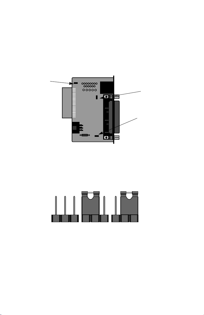
3.3.1 DB-25/RJ-11 & DB-25/RJ-45 STRAP SETTINGS
Figure 5 (below) shows strap locations for the Model
1000RCM12511 (DB-25/RJ-11) and the Model 1000RCM12545 (DB25/RJ-45) rear cards. These straps determine various grounding
characteristics for the RS-232 and twisted pair lines.
JB2
(peg 1 on left)
JB3
(peg 1 on top)
JB4
(peg 1 on left)
Figure 5. DB-25/RJ-11 & DB-25/RJ-45 strap locations
Figure 6 (below) shows the orientation of the rear interface card
straps. Observe that the strap can either be on pegs 1 and 2, or on
pegs 2 and 3.
123 123 123
Figure 6. Orientation of interface card straps
8
 Loading...