

Page 1

USER
MANUAL
MODEL 1060RC
AC Powered, Asynchronous
Short Range Modem:
Rack Mount Card
Part #07M1060RC-B
Doc #058021U
Revised 1/23/08
CERTIFIED
An ISO-9001
Certified Company
, Rev C
SALES OFFICE
(301) 975-1000
TECHNICAL SUPPORT
(301) 975-1007
http://www.patton.com
Page 2

1.0 WARRANTY INFORMATION
Patton Electronics warrants all Model 1060RC components to be
free from defects, and will—at our option—repair or replace the product
should it fail within one year from the first date of shipment.
This warranty is limited to defects in workmanship or materials, and
does not cover customer damage, abuse or unauthorized modification.
If this product fails or does not perform as warranted, your sole
recourse shall be repair or replacement as described above. Under no
condition shall Patton Electronics be liable for any damages incurred
by the use of this product. These damages include, but are not limited
to, the following: lost profits, lost savings and incidental or
consequential damages arising from the use of or inability to use this
product. Patton Electronics specifically disclaims all other warranties,
expressed or implied, and the installation or use of this product shall be
deemed an acceptance of these terms by the user.
1.1 RADIO AND TV INTERFERENCE
The Model 1060RC generates and uses radio frequency energy,
and if not installed and used properly—that is, in strict accordance with
the manufacturer's instructions—may cause interference to radio and
television reception. The Model 1060RC has been tested and found to
comply with the limits for a Class A computing device in accordance
with the specifications in Subpart J of Part 15 of FCC rules, which are
designed to provide reasonable protection from such interference in a
commercial installation. However, there is no guarantee that
interference will not occur in a particular installation. If the Model
1060RC does cause interference to radio or television reception, which
can be determined by turning the power off or removing the card, the
user is encouraged to try to correct the interference by one or more of
the following measures: moving the computing equipment away from
the receiver, re-orienting the receiving antenna and/or plugging the
receiving equipment into a different AC outlet (such that the computing
equipment and receiver are on different branches). In the event the
user detects intermittent or continuous product malfunction due to
nearby high power transmitting radio frequency equipment, the user is
strongly advised to take the following steps: use only data cables with
an external outer shield bonded to a metal or metalized connector; and,
configure the rear card as shown in section 3.4 of this manual.
1.2 CE NOTICE
The CE symbol on your Patton Electronics equipment indicates
that it is in compliance with the Electromagnetic Compatibility (EMC)
directive and the Low Voltage Directive (LVD) of the Union European
(EU). A Certificate of Compliance is available by contacting Technical
Support.
1
Page 3

1.3 SERVICE
All warranty and nonwarranty repairs must be returned freight
prepaid and insured to Patton Electronics. All returns must have a
Return Materials Authorization number on the outside of the shipping
container. This number may be obtained from Patton Electronics
Technical Support: (301) 975-1007; http://www.patton.com; or,
support@patton.com.
NOTE: Packages received without an RMA number will not be
accepted.
Patton Electronics' technical staff is also available to answer any
questions that might arise concerning the installation or use of your
Model 1060RC. Technical Service hours: 8AM to 5PM EST, Monday
through Friday.
2
Page 4

2.0 GENERAL INFORMATION
Thank you for your purchase of this Patton Electronics product.
This product has been thoroughly inspected and tested and is
warranted for One Year parts and labor. If any questions or problems
arise during installation or use of this product, please do not hesitate to
contact Patton Electronics Technical Support at (301) 975-1007.
2.1 FEATURES
• Data rates to 57.6 kbps
• Receiver optical isolation
• High speed surge protection
• Supports distances up to 14 miles (22.5 km)
• Mounts in Patton's 16-card rack chassis
• Bi-state LED indicators
• Point-to-point or multipoint operation
• Local and remote loopback test modes
• Hardware and software flow control support
• Pin assignable control signals
2.2 DESCRIPTION
The Model 1060RC Asynchronous Short Range Modem Rack
Card operates full duplex over two unconditioned twisted pair.
Supporting data rates to 57.6 kbps, the Model 1060RC has a maximum
range of 14 miles (22.5 km) (at 1200 bps over 19 AWG wire). The
Model 1060RC passes one control signal in each direction, and
features both optical isolation and Silicon Avalanche Diode surge
protection on the data line side.
The Model 1060RC is designed to mount in Patton's 2U high 19"
rack chassis. This 16 card chassis has a switchable 120/240 volt
power supply and mounts cards in a mid-plane architecture: The front
"brains" card can be plugged into different rear "interface" cards. This
means that the 1060RC can have several interface options, and can be
switched with other Patton short haul cards.
The Model 1060RC has two built-in diagnostic tools: local and
remote loopback test. Additionally, bi-level LEDs on the 1060RC's front
panel allow you to visually monitor communication.
3 4
Page 5
3.0 CONFIGURATION
This section describes the location and orientation of the Model
1060RC's configuration switches and provides detailed instructions on
setting each of the switches.
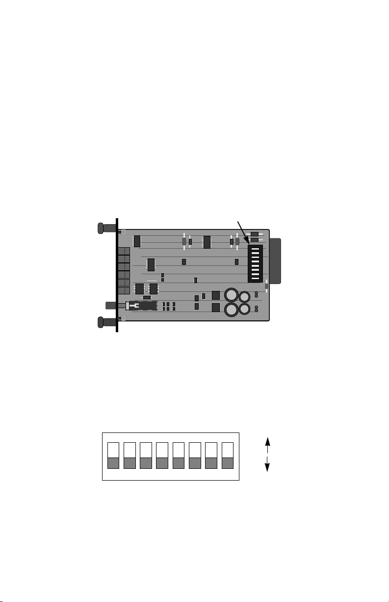
3.1 FRONT CARD CONFIGURATION
The Model 1060RC uses a set of eight DIP switches that allow
configuration to a wide range of asynchronous applications. These DIP
switches are accessible when the card is slid out of the rack chassis
(see Figure 1, below). Once configured, the Model 1060RC is
designed to operate transparently, without need for frequent reconfiguration.
Figure 1. Model 1060RC board, showing location of DIP switches
SW1
(SW1-1 on top)
The eight DIP switches on the Model 1060RC board allow you to
specify control signal pin assignments and carrier control method.
Figure 2 (below) shows the orientation of the DIP switches with respect
to "ON" and "OFF" positions.
ON
ON
12345678
Figure 2. Close up of DIP switches showing ON/OFF positions.
OFF
Page 6

3.2 "QUICK SET-UP" INSTRUCTIONS
In the majority of applications, you will not need an in-depth
knowledge of the Model 1060RC's capabilities to get up and running.
The following "quick set-up" DIP switch configurations cover most
Model 1060RC operating environments.
3.2.1 Point-to-Point Applications
If you are installing these units in a point-to-point application with a
computer, printer or terminal, configure the DIP switches on both Model
1060s as follows:
Number: 1 2 3 4 5 6 7
Switch
Positions ON ON ON OFF OFF OFF OFF
3.2.2 Multi-Point Applications
If you are installing these units in a multipoint application, configure
the DIP switches for master and slave units as follows:
Switch
Number: 1 2 3 4 5 6 7
Master positions ON ON ON OFF OFF OFF OFF
Slave positions ON ON ON OFF OFF OFF ON
3.3 SPECIAL CONFIGURATION
If your installation requires special configuration of the Model
1060RC, use the table below as a guide. This table shows all possible
Model 1060RC switch settings. Following the table are brief
descriptions of the Control Input, Control Output, +Voltage Output and
Carrier Controlled by (C
Mode Input Output Output Controlled
(DCE/DTE) (C
DCE 4 8 6 Disabled ON ON ON OFF OFF OFF OFF
DCE 4 8 6 Enabled ON ON ON OFF OFF OFF ON
DCE 4,11,20* 8 6 Disabled OFF ON ON ON OFF OFF OFF
DCE 4,11,20* 8 6 Enabled OFF ON ON ON OFF OFF ON
DCE 4 6 8 Disabled ON OFF OFF OFF ON ON OFF
DCE 4 6 8 Enabled ON OFF OFF OFF ON ON ON
DCE 4,11,20* 6 8 Disabled OFF OFF OFF ON ON ON OFF
DCE 4,11,20* 6 8 Enabled OFF OFF OFF ON ON ON ON
*Multiple input pins are "or-tied"—if any input goes low, carrier is dropped
Control Control +Voltage Carrier
)(C
In
) parameters shown in the table below.
in
Switch Settings
)(V
Out
) by (CIn) 1234567
Out
5
Page 7

Control Input (Cin):
The Control Input signal is used by the local Model 1060RC as an
input signal to “turn on” (in the “Enabled” settings) and allow data
transmission to the remote device. This is required for half-duplex/
switched-carrier environments as well as in hardware flow control
applications. In the “Disabled” settings, the 1060RC is always “turned
on” and sends a continuous carrier to the remote 1060RC.
Control Output (C
out
):
The Control Output signal is transmitted by the local Model
1060RC to its attached DTE device. This signal should be the same
logic state as the Control Input signal on the remote 1060RC. This
signal is required in half-duplex/switched carrier environments or in
hardware flow control applications.
+Voltage Output (+V
out
):
The +Voltage Output signal is a constant positive voltage that is
sent from the 1060RC to its attached DTE device.
Carrier Controlled by (C
):
in
When Carrier Controlled by Control Input is “Enabled”, the Model
1060RC is “turned on” by the corresponding C
Signal from the DTE.
in
In effect, the Control Input signal on the local 1060RC "controls" the
presence of "carrier" and the Control Output signal on the remote
1060RC. This setting is required in half-duplex/switched carrier
environments or in hardware flow control applications. When Carrier
Control by Control Input is “Disabled”, the 1060RC sends a continuous
carrier and is always “turned on”.
6
Page 8
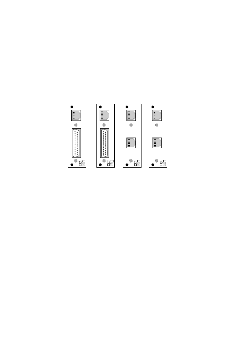
3.4 REAR CARD CONFIGURATION
The 1060RC has four interface card options: DB-25/RJ-11,
DB-25/RJ-45, RJ-45/RJ-11 and dual RJ-45. Each of these options
supports one RS-232 connection and one 4-wire connection (the RS232 port is always the
lower
port on the interface card). Figure 4
(below) illustrates the four different interface options for the Model
1060RC:
RJ-11 (6-wire)
DB-25 F
Figure 4. Model 1060RC interface card options
RJ-45 (8-wire) RJ-45 (8-wire) RJ-11 (6-wire)
DB-25 F RJ-45 (10-wIre) RJ-45 (10-wire)
Prior to installation, you will need to examine the rear card that you
have selected and ensure that it is configured properly for your
application. Each rear card is configured by setting straps located on
the PC board. Sections 3.4.1 and 3.4.2 describe the strap locations
and possible settings for each rear card.
Page 9
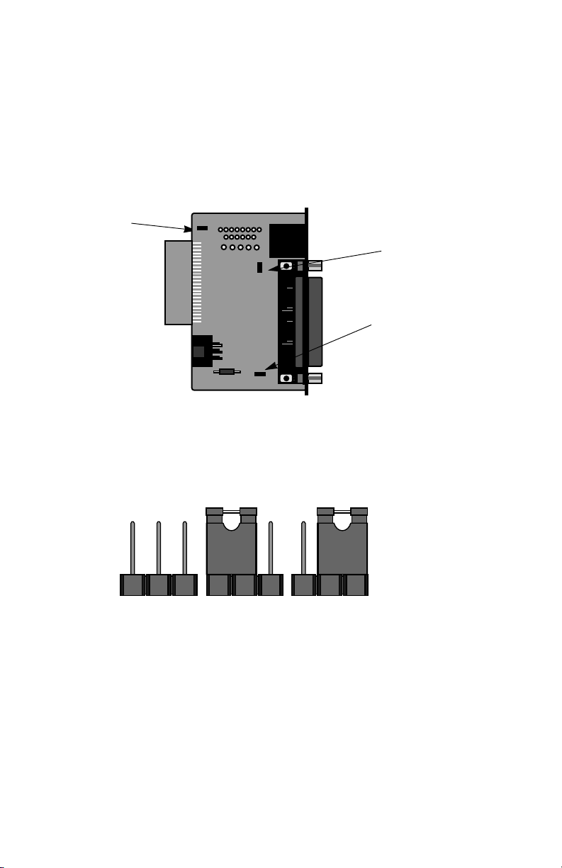
3.4.1 DB-25/RJ-11 & DB-25/RJ-45 Strap Settings
Figure 5 (below) shows strap locations for the Model
1000RCM12511 (DB-25/RJ-11) and the Model 1000RCM12545 (DB25/ RJ-45) rear cards. These straps determine various grounding
characteristics for the RS-232 and twisted pair lines.
JB2
(peg 1 on left)
JB3
(peg 1 on top)
JB4
(peg 1 on left)
Figure 5. DB-25/RJ-11 & DB-25/RJ-45 strap locations
Figure 6 (below) shows the orientation of the rear interface card
straps. Observe that the strap can either be on pegs 1 and 2, or on
pegs 2 and 3.
123 123 123
Figure 6. Orientation of interface card straps
87
Page 10

The table below provides an overview of strap functions for the DB25/modular cards. Following this overview is a detailed description of
each strap's function.
INTERFACE CARD STRAP SUMMARY TABLE #1
Strap Function Position 1&2 Position 2&3
JB2 Line Shield & FRGND Connected Open*
JB3 DTE Shield (Pin1) & FRGND Connected Open*
JB4 FRGND & SGND Connected Open*
* indicates factory default
Line Shield & FRGND (JB2)
This strap pertains to the line interface. In the connected (closed)
position, this strap links RJ-11 pins 1 and 6, or RJ-45 pins 2 and 7 to
frame ground. These pins can be used as connections for the twisted
pair cable shield. In the open (disconnected) position, pins 1 and 6 (or
2 and 7) remain connected to each other, but are "lifted" from the frame
ground.
JB2
Position 1&2 = Line Shield and FRGND Connected
Position 2&3 = Line Shield and FRGND Not Connected
DTE Shield (Pin 1) & FRGND (JB3)
In the connected (closed) position, this strap links DB-25 pin 1 and
frame ground. In the open (disconnected) position, pin 1 is "lifted" from
frame ground.
JB3
Position 1&2 = DTE Shield (Pin 1) and FRGND Connected
Position 2&3 = DTE Shield (Pin 1) and FRGND Not Connected
SGND & FRGND (JB4)
In the connected (closed) position, this strap links DB-25 pin 7
(Signal Ground) and frame ground. In the open (disconnected)
position, pin 1 is "lifted" from frame ground.
JB4
Position 1&2 = SGND (pin 7) and FRGND Connected
Position 2&3 = SGND (Pin 7) and FRGND Not Connected
9 10
Page 11

3.4.2 RJ-45/RJ-11 & RJ-45/RJ-45 Strap Settings
Figure 8 (opposite page) shows strap locations for the Model
1000RCM1D11 (RJ-45/RJ-11) and the Model 1000RCM1D45 (RJ-45/
RJ-45) rear cards. These straps determine various grounding
characteristics for the RS-232 and twisted pair lines.
JB2
(peg 1 on top)
JB6
(peg 1 on top)
JB5
(peg 1 on left)
Figure 8. RJ-45/RJ-11 & RJ-45/RJ-45 strap locations
The table below provides an overview of strap functions for the
modular/modular cards. Following the table is a detailed description of
each strap's function.
INTERFACE CARD STRAP SUMMARY TABLE #2
Strap Function Position 1&2 Position 2&3
JB2 Line Shield & FRGND Connected Open*
JB5 SGND & FRGND Connected Open*
JB6 DTE Pin 2 DSR* RI
* indicates factory default
Line Shield & FRGND (JB2)
This strap pertains to the line interface. In the connected (closed)
position, this strap links RJ-11 pins 1 and 6, or RJ-45 pins 2 and 7 to
frame ground. These pins can be used as connections for the twisted
pair cable shield. In the open (disconnected) position, pins 1 and 6 (or
2 and 7) remain connected to each other, but are "lifted" from frame
ground.
JB2
Position 1&2 = Line Shield and FRGND Connected
Position 2&3 = Line Shield and FRGND Not Connected
Page 12

SGND & FRGND (JB5)
This strap pertains to the DTE interface, which is a 10-position
modular RJ-45 jack. In the connected (closed) position, this strap links
modular pin 5 (Signal Ground) and frame ground. In the open
(disconnected) position, pin 5 is "lifted" from frame ground.
JB5
Position 1&2 = SGND (pin 5) and FRGND Connected
Position 2&3 = SGND (Pin 5) and FRGND Not Connected
DTE Interface Pin 2 (JB6)
This strap configures DTE interface pin 2 for Ready Start (DSR)
operation when placed on pegs 1 & 2. Placing the strap on pegs 2 & 3
is
not a valid option
with the Model 1060RC.
JB6
Position 1&2 = Ready Start (DSR) Operation
Position 2&3 = Not a valid option
when using this rear interface card in conjunction
Page 13

4.0 INSTALLATION
This section describes the functions of the Model 1000R16 rack
chassis, tells how to install front and rear Model 1060RC cards into the
chassis, and provides diagrams for wiring up the interface connections
correctly.
4.1 THE MODEL 1000R16 RACK CHASSIS
The 1000R16 Rack Chassis (shown in figure 10, below) has
sixteen short range modem card slots, plus its own power supply.
Measuring only 3.5" high, each Model 1060RC is designed to occupy
only 2U in the 19" Model 1000R16. Sturdy front handles allow the
1000R16 to be extracted and transported conveniently.
Figure 10: Model 1000R16 Rack Chassis with power supply
4.1.1 The Rack Power Supply
The power supply included in the Model 1000R16 rack uses the
same mid-plane architecture as the modem cards. The front card of
the power supply slides in from the front, and the rear card slides in
from the rear. They plug into one another in the middle of the rack.
The front card is then secured by thumb screws and the rear card by
conventional metal screws.
WARNING! There are no user-serviceable parts in the
power supply section of the Model 1060RC Series.
Voltage setting changes and fuse replacement should only
be performed by qualified service personnel. Contact
Patton Electronics Technical support at (301)975-1007 for
more information.
1211
Page 14

Switching the Power Supply On and Off
The power supply on/off switch is located on the front panel. When
plugged in and switched on, a red front panel LED will glow. Since the
Model 1000R16 is a "hot swappable" rack,
cards to be installed before switching on the power supply
supply may be switched off at any time without harming the installed
cards.
it is not necessary for any
. The power
NOTE: Please refer to the Model 1000RP Series User Manual
and DC Rack Mount Power Supplie
replacement information.
4.2 INSTALLING THE MODEL 1060RC INTO THE CHASSIS
The Model 1060RC is comprised of a front "brains" card and a rear
"connections" card. The two cards meet inside the rack chassis and
plug into each other by way of mating 50 pin card edge connectors.
Use the following steps as a guideline for installing each Model 1060RC
into the Model 1000R16 rack chassis:
1. Slide the rear "connections" card into the back of the
chassis along the metal rails provided.
2. Secure the rear card using the metal screws provided.
3. Slide the "brains" card into the front of the chassis. It should
meet the rear card when it's almost all the way into the
chassis.
gently
4. Push the front card
the rear card. It should "click" into place.
5. Secure the front card using the thumb screws.
NOTE: Since the Model 1000R16 chassis allows "hot swapping"
of cards, it is
install or remove a Model 1060RC.
4.3 RS-232 CONNECTION
not necessary to power down
into the card-edge receptacle of
s for fuse and power card
the rack when you
AC
The Model 1060RC offers two port options for connecting the
RS-232 interface to your computing hardware: DB-25 female and
10-pin RJ-45 female (the RS-232 port is always the
interface card). The DB-25 is pinned according to the RS-232C/V.24
interface standard. The 10-pin RJ-45 is pinned according to the
EIA/TIA-561 interface standard. For specific interface pin-outs, please
refer to the diagrams in Appendix D of this manual.
13 14
lower
port on the
Page 15

The Model 1060RC is wired to connect to a DTE. If your RS-232
output device is a DTE, use a
Model 1060RC. If your RS-232 output device is DCE, call Patton
Technical Support at (301) 975-1007 for specific installation
instructions.
straight though cable
to connect to the
Notice! Any terminal cable connected to the Model
1060RC must be shielded cable, and the outer shield must
be 360 degree bonded–at both ends–to a metal or
metalized backshell.
4.4 TWISTED PAIR CONNECTION
The Model 1060RC operates over two twisted pair. In
applications, the twisted pair wire must be 26 AWG or thicker,
unconditioned, dry, metallic wire. Both shielded and unshielded wire
yield favorable results. Note: The Model 1060RC can only
communicate in a closed data circuit with another Model 1060RC. Dialup analog circuits, such as those used with a standard Hayes-type
modem, are
wire grades, please refer to the diagrams in Appendix B.
4.4.1 Point-to-Point Twisted Pair Connection
The 6-position RJ-11 and 8-position RJ-45 jack options for the
Model 1060RC (always the
prewired for a standard TELCO wiring environment. Connection of a
4-wire twisted pair circuit between two or more Model 1060RCs
requires a
following page.
SIGNAL PIN# COLOR COLOR PIN# SIGNAL
GND 1 Blue..................White 6 GND
RCV- 2 Yellow...............Red 4 XMT-
XMT+ 3 Green ...............Black 5 RCV+
XMT- 4 Red ..................Yellow 2 RCV-
RCV+ 5 Black ................Green 3 XMT+
GND 6 White................Blue 1 GND
not acceptable.
crossover cable
For further information about acceptable
upper
jack on the rear interface card) are
as shown in the figures below and on the
RJ-1
1
all
Page 16

RJ-45
SIGNAL PIN# COLOR COLOR PIN# SIGNAL
GND 2 Orange.............Brown 7 GND
RCV- 3 Black................Green 5 XMT-
XMT+ 4 Red ..................Yellow 6 RCV+
XMT- 5 Green...............Black 3 RCV-
RCV+ 6 Yellow ..............Red 4 XMT+
GND 7 Brown ..............Orange 2 GND
4.4.2 Multipoint Twisted Pair Connection
Figure 11 (below) shows how to wire two-pair cables properly for a
Model 1060RC star topology.
HOST FIRST SLAVE SECOND SLAVE
XMT+ RCV+
RCV+
XMT- RCV-
RCV-
RCV+ XMT+
XMT+
RCV- XMT-
XMT-
Figure 11. Two-pair star wiring for Model 1060RC host and slaves
RJ-11
1 - Blue
2 - Yellow
3 - Green
4 - Red
5 - Black
6 - White
RJ-45
1 - Blue
2 - Orange
3 - Black
4 - Red
5 - Green
6 - Yellow
7 - Brown
8 - Slate
Notice! Any modular twisted pair cable connected to
the Model 1060RC must be shielded cable, and the outer
shield must be properly terminated to a shielded modular
plug on both ends of the cable.
15 16
Page 17

5.0 OPERATION
Once you have configured each Model 1060RC and connected the
cables, you are ready to operate the units. Section 5.0 describes the
LED status monitors, the power-up procedure and the use of the built-in
loopback test modes.
5.1 LED STATUS MONITORS
The Model 1060RC features ten front panel status LEDs that
indicate the condition of the modem and communication link. Figure 12
(below) shows the relative front panel positions of the LEDs. Following
figure 12 is a description of each LED's function.
Model 1060RC
Power
TD
RD
Cntrl
In
Cntrl
Out
Test
Figure 12. The Model 1060RC front panel, showing LED positions
Power glows green when power is applied to the Model
1060RC front card.
TD & RD The green "TD" and "RD" indicators blink to show
positive state data activity. The red "TD" and "RD"
indicators blink to show negative state data activity.
Solid red indicates a connection in an idle state.
and glow red to show that either control signal is off.
Cntrl
in
Cntrl
out
Glow green to show that either control signal is on.
When the 1060RC is connected to a DTE, Control In
will glow green for a positive polarity on the Control
Input signal. Control Out will glow green for an
incoming signal from the line.
Test glows green when the loopback test modes are
activated.
Page 18

5.2 POWER-UP
There is no power switch on the Model 1060RC: Power is
automatically applied to the 1060RC when its card-edge connector
makes contact with the chassis' mid-plane socket, or when the chassis'
power supply is turned on.
Note: The 1060RC is a "hot swappable"
card—it will not be damaged by plugging it in or removing it while the
rack is powered up.
When the local and remote Model 1060RCs are
are passing data
• PWR = green
• TD & RD = flashing red and green
• Control In & Control Out = green
• TEST = off
normally
, the following LED conditions will exist:
both
powered up, and
17 18
Page 19

5.3 TEST MODES
The Model 1060RC offers two diagnostic modes: local analog loop
and remote analog loop. These test modes are activated
simultaneously
by depressing the "Test" button on the front panel of the
Model 1060RC.
Local Analog Loop
The Local Analog Loop test mode causes any data sent to the
local 1060RC by the local RS-232 device to be echoed
back
to that
RS-232 device. For example, characters typed on the keyboard of a
terminal will appear on the terminal screen (see Figure 13 on the
following page). If characters are not echoed back, check the
connection between the local RS-232 device and the local 1060RC. All
1060RCs in the system should be tested in this manner.
Remote Analog Loop
The Remote Analog Loop test mode causes any characters sent
from the
remote
local
remote
1060RC to the local 1060RC to be returned back to the
device (see figure 13 on the following page). Note: Only the
1060RC should be in "test" mode. The remote 1060RC should
be in "normal" operating mode or this test will not work. If no characters
are echoed back, check the wiring between the two 1060RCs. Be sure
to wire the units according to the instructions in section 4.0.
TD
RD
TD
RD
TX+
TX-
RX-
RX+
Local 1060RC
In Normal Mode
TX+
TX-
RXRX+
Local 1060RC
In Loopback Mode
Figure 13. Normal operating mode vs. loopback test mode
RX+
RX-
TXTX+
Remote 1060RC
In Normal Mode
RX+
RX-
TXTX+
Remote 1060RC
In Normal Mode
RD
TD
RD
TD
Page 20

APPENDIX A
SPECIFICATIONS
Transmission Format: Asynchronous
External Interface: RS-232C/CCITT V.24 connection via DB-25
female; EIA/TIA-561 connection via RJ-45 (10 wire); twisted pair
connection via RJ-11 or RJ-45 (8 wire)
Internal Interface: Connection to Model 1000R16 rack chassis via 50
pin male card edge
Transmission Line: 4-wire, unconditioned twisted pair, 19-26 AWG,
20pf/ft or better
Data Rates: 0 - 57.6 Kbps
Controls: Carrier constantly "ON" or "controlled by RTS"
Applications: Point-to-point or multi-point
Indicators: Bi-level LED indicators (two each) for Transmit Data,
Receive Data, Control In and Control Out; bi-level indicators (one
each) for Power and Test
Diagnostics: Local and remote analog loopback, activated by front
panel push button
Receiver Optical Isolation: 150V AC
Surge Protection: Silicon Avalanche Diodes, 600 watts RMS power
dissipation @ 1 ms, with response time of less than 1 pS
Power Supply: Rack-mount power supply is switchable between 120V
and 240V AC; rack chassis supplies 10V AC to the Model
1060RC, typical Model 1060RC consumption is 700 mW
Fuse: 400 mA for 120V applications; 200 mA for 240V applications
°
Temperature: 0-50
C / 32-122°F
Humidity: 0-95%, non-condensing
Dimensions: 0.95"h x 3.1"w x 5.4"l
19 20
Page 21

CABLE RECOMMENDATIONS
The Patton Model 1060RC operates at frequencies of 100kHz or
less and has been performance tested by Patton technicians using
twisted-pair cable with the following characteristics:
ire Gauge Capacitance Resistance
W
19 AWG 83nf/mi or 15.72 pf/ft. .0163W/ft.
22 AWG 83nf/mi or 15.72 pf/ft. .0326W/ft.
24 AWG 83nf/mi or 15.72 pf/ft. .05165W/ft.
Using or simulating cable with the above characteristics, the
following data rate/distance results were obtained by Patton during
bench tests:
APPENDIX B
Data Rate (Bps)
57,600 2.5 1.8 1.3
38,400 3.7 2.3 1.7
19,200 5.1 3.4 2.4
9,600 6.7 4.6 3.7
4,800 9.4 6.6 5.3
2,400 11.5 9.3 7.6
1,200 14.0 12.0 9.6
To gain optimum performance from the 1060RC, please keep the
following guidelines in mind:
•
Always
use twisted pair wire—this is not an option.
• Use twisted pair wire with a capacitance of 20pf/ft or less.
• Avoid twisted pair wire thinner than 26 AWG (i.e. avoid higher
AWG numbers than 26).
• Use of twisted pair with a resistance greater than the above
specifications may cause a reduction in maximum distance
obtainable. Functionality should not be affected.
• Environmental factors too numerous to mention can affect the
maximum distances obtainable at a particular site. Use the above
data rate/distance table as a
Gauge (AWG) / Distance (Mi)
19 22 24
general guideline only.
Page 22

FACTORY REPLACEMENT PARTS
APPENDIX C
The Patton Model 1060RC rack system features interchangeable
rear half cards, power cords/fuses for international various operating
environments and other user-replaceable parts. Model numbers and
descriptions for these parts are listed below:
Patton Model #
Description
1000RPEM..........................120/240V Rear Power Entry Module
1000RPSM-2.......................120/240V Front Power Supply Module
1000RPEM-DC ...................DC Rear Power Entry Module
1000RPSM-48A ..................48V Front Power Supply Module
1000RPEM-V ......................120/240V CE Compliant Rear Power
Entry Module
1000RPSM-V ......................120/240V CE Compliant Front Power
Supply Module
0805US ...............................American Power Cord
0805EUR.............................European Power Cord CEE 7
0805UK ...............................United Kingdom Power Cord
0805AUS.............................Australia/New Zealand Power Cord
0805DEN.............................Denmark Power Cord
0805FR ...............................France/Belgium Power Cord
0805IN.................................India Power Cord
0805IS.................................Israel Power Cord
0805JAP..............................Japan Power Cord
0805SW ..............................Switzerland Power Cord
05R16FPB1.........................Single Width Blank Front Panel
05R16FPB4.........................4-Wide Blank Front Panel
05R16RPB1 ........................Single Width Blank Rear Panel
05R16RPB4 ........................4-Wide Blank Rear Panel
0821R4................................400 mA Fuse (5x20mm)
Littlefuse 239.400 or equivalent
0821R2................................200 mA Fuse (5x20mm)
Littlefuse 239.200 or equivalent
056S1..................................Set of 16 #4 pan head screws/washers
21 22
Page 23

APPENDIX D
INTERFACE STANDARDS
DIRECTION STANDARD RS-232C/V.24 "DCE" SETTING DIRECTION
1- (FG) Frame Ground
2- (TD) Transmit Data To 1060RC
3- (RD) Receive Data From 1060RC
4- (RTS) Request to Send To 1060RC
5- (CTS) Clear to Send From 1060RC
6- (DSR) Data Set Ready From 1060RC
7- (SG) Signal Ground
To 1060RC Data Term. Ready (DTR) - 20
8- (DCD) Data Carrier Detect From 1060RC
EIA/TIA-561 REFERENCE - 8 Wire RJ-45
Contact Number Circuit Description
1 125 Ring Indicator or DSR
2 109 Received Line Signal Indicator
3 108 / 2 DTE Ready
4 102 Signal Common
5 104 Received Data
6 103 Transmitted Data
7 106 Clear to Send
8 105 / 133 Request to Send / Ready for Receiving
PATTON MODIFIED MODULAR INTERFACE - 10 Wire RJ-45
Contact Number Circuit Description
1 N/A Receive Clock (Not Used for 1060RC)
2 125 Ring Indicator or DSR
3 109 Received Line Signal Indicator
4 108 / 2 DTE Ready
5 102 Signal Common
6 104 Received Data
7 103 Transmitted Data
8 106 Clear to Send
9 105 / 133 Request to Send / Ready for Receiving
10 N/A Transmit Clock (Not Used for 1060RC)
Page 24

APPENDIX E
BLOCK DIAGRAM
23
Page 25

Page 26

Page 27

Page 28

Dear Valued Customer,
Thank you for purchasing Patton Electronics products! We do
appreciate your business. I trust that you find this user manual helpful.
We manufacture one of the widest selections of data
communications products in the world including CSU/DSU's, network
termination units, powered and self-powered short range modems, fiber optic
modems, interface converters, baluns, electronic data switches, data-line surge
protectors, multiplexers, transceivers, hubs, print servers and much more. We
produce these products at our Gaithersburg, MD, USA, facility, and can
custom manufacture products for your unique needs.
We would like to hear from you. Please contact us in any of the
following ways to tell us how you like this product and how we can meet your
product needs today and in the future.
Web: http://www.patton.com
Sales E-mail: sales@patton.com
Support E-mail: support@patton.com
Phone - Sales (301) 975-1000
Phone - Support (301) 975-1007
Fax: (301) 869-9293
Mail: Patton Electronics Company
7622 Rickenbacker Drive
Gaithersburg, MD 20879 USA
We are committed to a quality product at a quality price. Patton
Electronics is ISO 9001 certified. We meet and exceed the highest
standards in the industry (CE, UL, etc.).
It is our business to serve you. If you are not satisfied with any
aspect of this product or the service provided from Patton Electronics or its
distributors, please let us know.
Thank you.
Burton A.Patton
Vice President
P.S. Please tell us where you purchased this product.
 Loading...