

Page 1
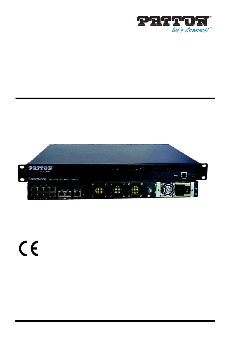
SmartNode™ 10100 Series
TDM+VoIP Smart Media Gateway
Quick Start Guide
This is a Class A device and is not intended for use in a residential environment.
Part Number: 07MSN10100-QS, Rev. A
Revised: April 9, 2014
Sales Office: +1 (301) 975-1000
Technical Support: +1 (301) 975-1007
E-mail: support@patton.com
WWW: www.patton.com
Page 2
• Do not open the device when the power cord is connected. For sys-
WARNING
WARNING
tems without a power switch and without an external power
adapter, line voltages are present within the device when the power
cord is connected.
• For devices with an external power adapter, the power adapter shall
be a listed Limited Power Source The mains outlet that is utilized to
power the device shall be within 10 feet (3 meters) of the device,
shall be easily accessible, and protected by a circuit breaker in compliance with local regulatory requirements.
• For AC powered devices, ensure that the power cable used meets all
applicable standards for the country in which it is to be installed.
• For AC powered devices which have 3 conductor power plugs (L1, L2
& GND or Hot, Neutral & Safety/Protective Ground), the wall outlet
(or socket) must have an earth ground.
• For DC powered devices, ensure that the interconnecting cables are
rated for proper voltage, current, anticipated temperature, flammability, and mechanical serviceability.
• WAN, LAN & PSTN ports (connections) may have hazardous voltages
present regardless of whether the device is powered ON or OFF.
PSTN relates to interfaces such as telephone lines, FXS, FXO, DSL,
xDSL, T1, E1, ISDN, Voice, etc. These are known as “hazardous network voltages” and to avoid electric shock use caution when working
near these ports. When disconnecting cables for these ports, detach
the far end connection first.
• Do not work on the device or connect or disconnect cables during periods of lightning activity.
This device contains no user serviceable parts. This device can only be
repaired by qualified service personnel.
In accordance with the requirements of council directive 2002/96/EC on Waste of
Electrical and Electronic Equipment (WEEE), ensure that at end-of-life you separate
this product from other waste and scrap and deliver to the WEEE collection system in
your country for recycling.
2 SmartNode 10100 Series Quick Start Guide
Page 3
Electrostatic Discharge (ESD) can damage equipment and impair electrical
CAUTION
circuitry. It occurs when electronic printed circuit cards are improperly
handled and can result in complete or intermittent failures. Do the following to prevent ESD:
• Always follow ESD prevention procedures when removing and replacing cards.
• Wear an ESD-preventive wrist strap, ensuring that it makes good skin
contact. Connect the clip to an unpainted surface of the chassis frame
to safely channel unwanted ESD voltages to ground.
• To properly guard against ESD damage and shocks, the wrist strap
and cord must operate effectively. If no wrist strap is available,
ground yourself by touching the metal part of the chassis.
1.0 Before you Begin
In the box, you will find:
• One SmartNode 10100
• One set of mounting brackets with screws
• One DB-9 to RJ-45 adapter
• Three CAT5 Ethernet straight cables (male-male), three meters in length
• One warranty sheet
• One packing slip
• One SmartNode 10100 Series Quick Start Guide
• One SmartNode 10100 Important Notice sheet with unique information for your specific unit
To install the SN10100, you will need (not included):
• Two AC power cords
• 19” equipment rack
Note Two DC power cable are included with DC units.
SmartNode 10100 Series Quick Start Guide 3
Page 4
2.0 Installing the rack hardware
S
m
art
Nod
e
™
C
o
n
s
o
l
e
E
th
e
rn
e
t
P
o
w
e
r
T
DM
+VoIP
S
m
a
rt
M
ed
ia
G
a
te
way
M
a
nag
e
men
t
Attach the SmartNode
to the equipment rack
Attach the bracket
to the SmartNode
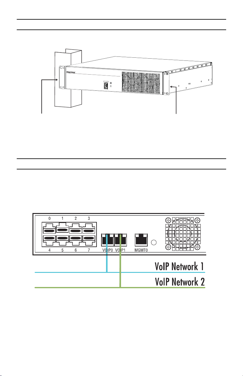
1. Connect the Ethernet port to your management network.
Figure 1. Installing the SN10100
3.0 Connecting to the VoIP Network
1. Connect a CAT5 Ethernet cable to VoIP0 at the rear of the SN10100. Connect the other end of the same
CAT5 cable to the Gigabit Ethernet switch.
2. If your system employs a second Gigabit Ethernet switch for redundancy, connect a second CAT5 Ethernet
cable to VoIP1and the other end to the second Gigabit Ethernet switch.
Figure 2. Connecting the VoIP ports
4 SmartNode 10100 Series Quick Start Guide
Page 5

4.0 Connecting to the PSTN Network
A SN10100 with 8 RJ48C type ports enables the connection to T1/E1 lines.
Note T1/E1 ports are activated by software license; the number of active ports
depends on the licenses purchased.
1. Start with port 0, located at the top and leftmost position. Connect one cable between this port and the
T1/E1 line.
2. Repeat step 1, using the next available port.
Figure 3. Port Interface to the PSTN
5.0 Connecting to the Power source
5.1 AC Power
The SN10100 connects to two independent power sources. If only one power source is used, press the green button at the rear of the unit to disable the audible alarm.
1. Connect an AC power cable between the AC connector of the SN10100 and an AC supply.
SmartNode 10100 Series Quick Start Guide 5
Page 6

2. Power up the SN10100 by turning on its power switch(es).
Figure 4. AC Power Connection(s)
5.2 DC Power
The SN10100 DC models are furnished with one or two DC power connection ports and is supplied with two DC
power cables.
1. Connect one DC cable to the DC outlet at the rear of the SN10100
2. Connect one lead of the DC power cable to the positive terminal of the DC power source.
3. Connect the other lead of the DC power cable to the negative side of the DC power source.
4. Repeat steps 1-3 for the second DC power source, if necessary.
Figure 5. DC Power Connection(s)
6 SmartNode 10100 Series Quick Start Guide
Page 7

6.0 Connecting to the Control host
1. Connect to the Control host through the Console Serial port (see 6.1 “Connecting the Console Serial port”)
OR the Ethernet management interface (see 6.2 “Connecting the Ethernet management interface”).
The IP address of the management port is 192.168.200.10/24. If it is not possible to connect to the
management port via IP, use the serial cable to connect to the SmartNode Control host for the first time.
2. Default HOSTNAME is the Control host serial number, which can be found in the “Important Notice” sheet
included with your shipment.
3. Refer to the “Important Notice” sheet for the username and password to log onto the Control host. Navi-
gate to: HTTP://HOSTNAME:12358, to configure the SmartNode unit. (username/password: root/root)
6.1 Connecting the Console Serial port
1. Connect the supplied CAT5 RJ-45 (male-male) cable between the COM port of your computer and the
serial port (labeled 1010) of the SN10100.
2. If your computer’s serial port features a DB9 connector, use the DB9 to RJ-45 adapter supplied with your
SN10100. If your computer’s serial port features a USB connector, you will need to provide a USB to DB9
adapter.
Figure 6. Computer to the Console Serial port
6.2 Connecting the Ethernet management interface
1. Connect the supplied CAT5 Ethernet cable to the management port labeled Ethernet on the front of the
SN10100.
SmartNode 10100 Series Quick Start Guide 7
Page 8

2. Login to the SmartNode using the specific credentials included on the “Important Notice” sheet that
shipped with your unit. The management port is configured with a static Class C IP address by default.
Figure 7. Conneting the management interface
7.0 Configuring the SmartNode
Access the SmartNode through the Console Management port, or through the Ethernet management port. Refer
to the following sections for more information:
• 7.1 “Accessing the SmartNode via the Console Serial port”
• 7.2 “Accessing the SmartNode via the Ethernet management port”
7.1 Accessing the SmartNode via the Console Serial port
Logging into the SmartNode Console
1. To physically connect the Consol Serial port, follow the instructions in section 6.1, “Connecting the Console
Serial port” on page 7.
2. To communicate with the SN10100 through the consol port, you must first configure a terminal emulator
or console application (such as HyperTerminal or Putty) in order to configure initial settings. Configure
the terminal emulator with the following settings:
Baud rate Data rate Parity Stop bits Flow control
9600 8 bits None 1 None
3. Login to the console using the specific credentials included on the “Important Notice” sheet that shipped
with your unit. (If you do not have the “Important Notice” sheet, contact support@patton.com.) The factory default configuration for the Ethernet Interface IP address is 192.168.200.10/24.
8 SmartNode 10100 Series Quick Start Guide
Page 9

7.2 Accessing the SmartNode via the Ethernet management port
Logging into the SmartNode via SSH
1. To physically connect the Ethernet management port, follow the instructions in section 6.2, “Connecting
the Ethernet management interface” on page 7.
2. To access the SN10100, you must use an SSH connection. The password is set at the factory and is indi-
cated on the “Important Notice” sheet included with your unit. (If you do not have the “Important
Notice” sheet, contact support@patton.com.)
3. The factory default configuration for the Managmeent Ethernet Interface is a Static IP address:
192.168.200.10/24.
Preparing for Web Management
After logging into the SN10100 via the console port or SSH, a control menu displays. This menu allows you to
complete simple tasks like setting the time zone and configuring the management IP Address, and more complicated tasks like advanced debugging.
For debugging assistance, contact Patton’s Support team at support@patton.com. Once your IP Address and
Time Zone are set, there are no more configuration steps in the CLI and you may proceed to the web management page.
8.0 Logging into the Web Interface
This section describes how to login and navigate the SmartNode 10100 Web Portal.
The first step involved in initially configuring any Smart Media system involves logging on to the Web Portal. This
can be divided into two distinct tasks: connecting to the web server and logging on to the Web Portal. For establishing IP connectivity refer to section 7.2, “Accessing the SmartNode via the Ethernet management port” on
page 9.
8.1 Connecting to the web server
Using a web browser, connect to the Web Portal by typing the following in you address bar:
– http://[DEVICE HOST NAME]:12358
or, alternately,
– http://[DEVICE IP ADDRESS]:12358
8.2 Logging onto the Web Portal
In order to log onto the Web Portal configuration tool, enter the root user ID and password. The default values
for these parameters are:
– User ID: root
SmartNode 10100 Series Quick Start Guide 9
Page 10

– Default password: root
9.0 Additional Information
Refer to the following manuals—available online at www.patton.com/manuals—for detailed information
about installing, configuring and operating the SN10100 models, along with warranty, trademark and compliance information.
• SmartNode 10100 Series User Manual —www.patton.com/manuals/SN10100.pdf
• Smart Media System Software Configuration Guide —www.patton.com/manuals/SmartMedia-scg.pdf
A.0 Compliance Information
A.1 Compliance
EMC
• FCC Part 15, Class A
• EN55022, Class A
• EN ETSI 300 386 V1.3.3
Low-Voltage Directive (Safety)
• UL 60950-1/CSA C22.2 No. 60950-1
• IEC/EN60950-1
A.2 Radio and TV Interference
This device generates and uses radio frequency energy, and if not installed and used properly—that is, in strict
accordance with the manufacturer’s instructions—may cause interference to radio and television reception. This
equipment has been tested and found to comply with the limits for a Class A computing device in accordance with
specifications in Subpart B of Part 15 of FCC rules, which are designed to provide reasonable protection from
such interference in a commercial installation. However, there is no guarantee that interference will not occur in
a particular installation. If the equipment does cause interference to radio or television reception, which can be
determined by disconnecting the unit, try to correct the interference by one or more of the following measures:
moving the computing equipment away from the receiver, re-orienting the receiving antenna and/or plugging
the receiving equipment into a different AC outlet (such that the computing equipment and receiver are on different branches).
10 SmartNode 10100 Series Quick Start Guide
Page 11

A.3 CE Declaration of Conformity
Patton Electronics, Inc declares that this device is in compliance with the essential requirements and other relevant provisions of Directive 1999/5/EC. The Declaration of Conformity may be obtained from Patton Electronics, Inc at www.patton.com/certifications
.
The safety advice in the documentation accompanying this device shall be obeyed. The conformity to the above
directive is indicated by CE mark on the device.
A.4 Authorized European Representative
D R M Green, European Compliance Services Limited.
Avalon House, Marcham Road, Abingdon,
Oxon OX14 1UD, UK
B.0 Customer and Technical Support
Toll-Free VoIP support: call sip:support@patton.com with a VoIP SIP client
Online support: www.patton.com, e-mail support: support@patton.com—answered within 1 business
day
Telephone support:
• Standard: +1 (301) 975-1007 (USA), Monday–Friday: 8:00 am to 5:00 pm EST (1300 to
2200 UTC/GMT)
• Alternate: +41 (0)31 985 25 55 (Switzerland), Monday–Friday: 9:00 am to 5:30 pm CET (08:00 to 16:30
UTC/GMT)
Fax: +1 (301) 869-9293 (USA) or +41 (0)31 985 25 26 (Switzerland)
SmartNode 10100 Series Quick Start Guide 11
Page 12

Copyright statement
Copyright © 2013, Patton Electronics Company. All rights reserved.
The information in this document is subject to change without notice. Patton Electronics assumes no
liability for errors that may appear in this document.
Trademarks statement
The term SmartNode is a trademark of Patton Electronics Company. All other trademarks presented in this document are the property of their respective owners.
Warranty, Trademark, & Compliance Information
For warranty, trademark and compliance information, refer to the user manual for your SN10100 model, avail-
able online at www.patton.com/manuals.
12 SmartNode 10100 Series Quick Start Guide
 Loading...