

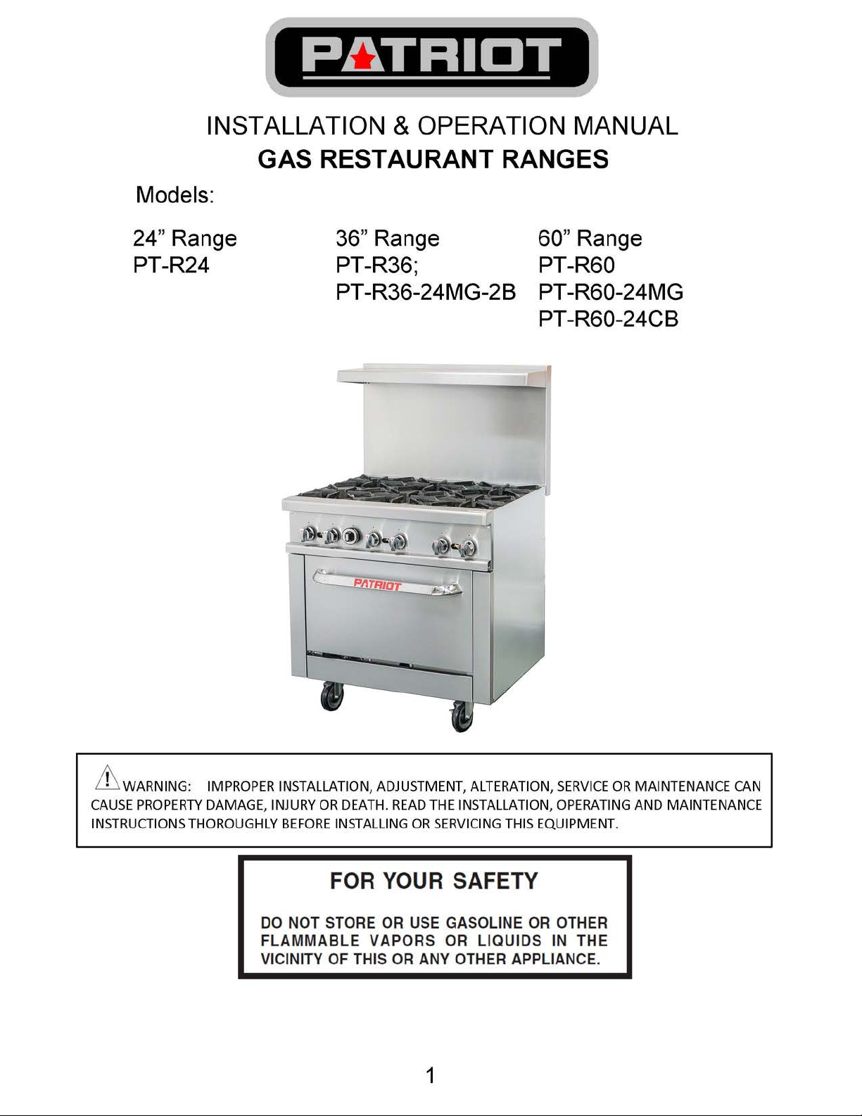
Page 1
Page 2
IMPORTANT FOR YOUR SAFETY
THIS MANUAL HAS BEEN PREPARED FOR PERSONNEL QUALIFIED TO INSTALL GAS EQUIPMENT, WHO SHOULD PERFORM THE
INITIAL FIELD START-UP AND ADJUSTMENTS OF THE EQUIPMENT COVERED BY THIS MANUAL.
POST IN A PROMINENT LOCATION THE INSTRUCTIONS TO BE FOLLOWED IN THE EVENT THE SMELL OF GAS IS DETECTED. THIS
INFORMATION CAN BE OBTAINED FROM THE LOCAL GAS SUPPLIER.
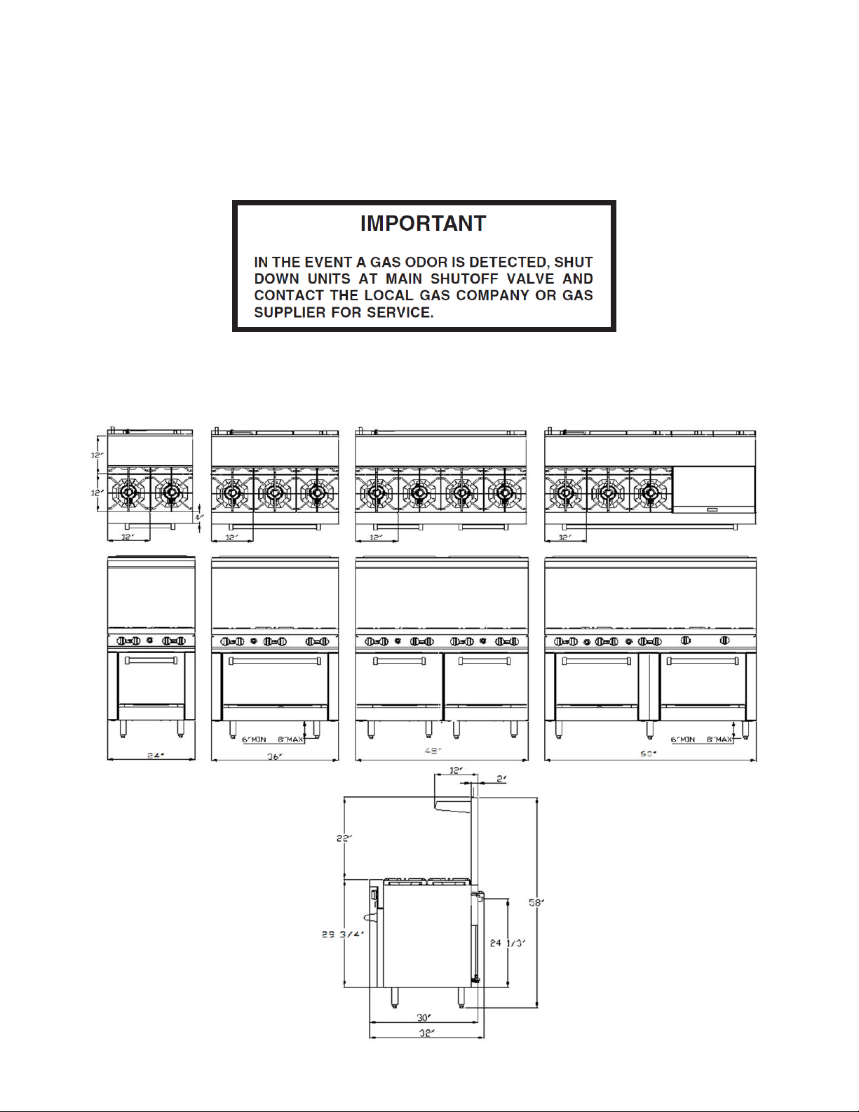
Dimension of Overall
24” Range 36” Range 48”Range 60”Range
2
Page 3
Page 4

Installation, Operation and Care:
PLEASE KEEP THIS MANUAL FOR FUTURE REFERENCE
GENERAL
Ranges are produced with quality workmanship and material. Proper installation, usage and
maintenance of your range will result in many years of satisfactory performance.
Suggests that you thoroughly read this entire manual and carefully follow all of the instructions
provided.
THIS APPLIANCE IS EQUIPPED FOR NATURAL GAS,
for conversion to LP gas please see gas conversion instruction manual
attached. Orifices necessary for LP (propane) (natural) conversion are
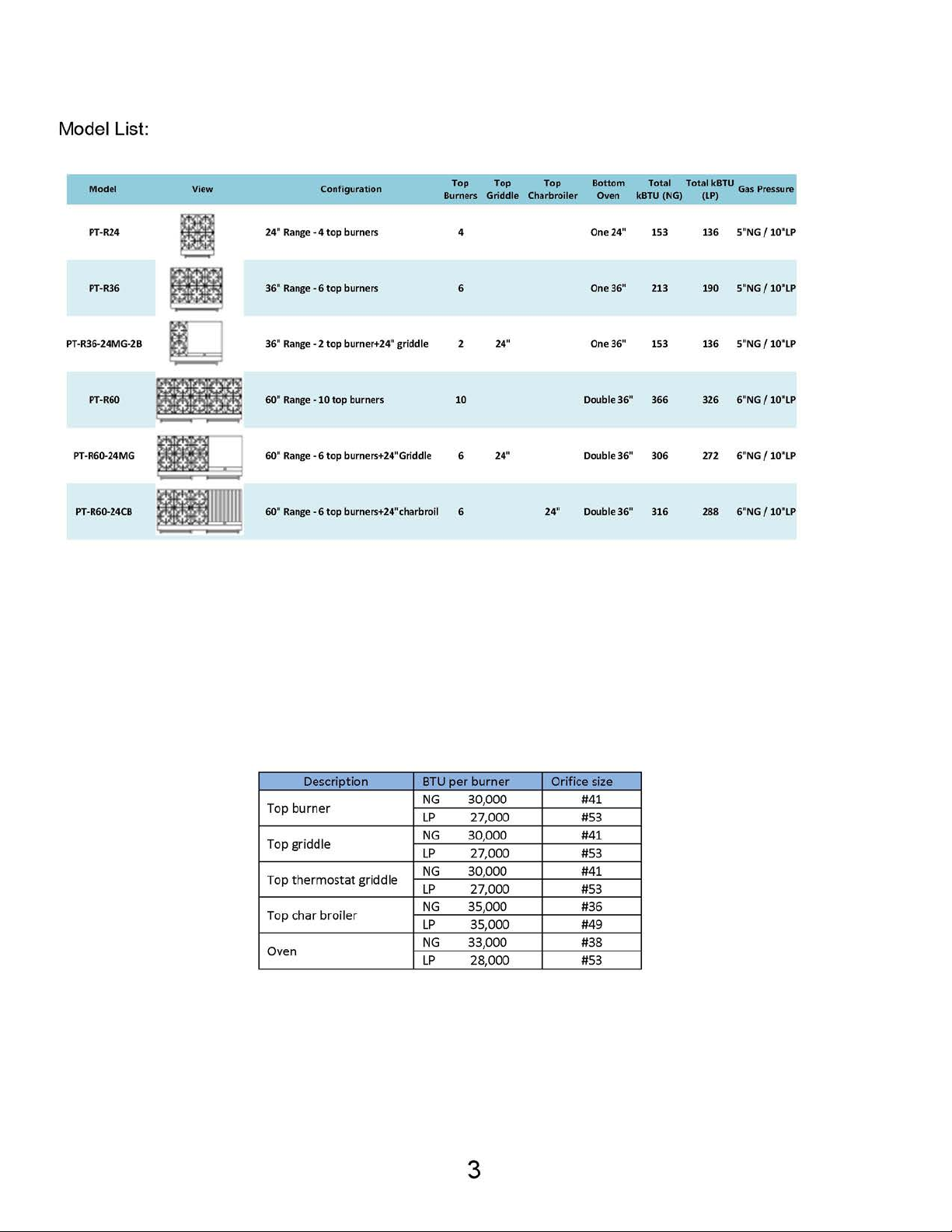
provided. Please refer to page 3 the orifice size list when you do gas
conversion
INSTALLATION
UNCRATING
This range was inspected before leaving the factory. The transportation company assumes
full responsibility for safe delivery upon acceptance of the shipment. Immediately after
unpacking, check for possible shipping damage. If the range is found to be damaged, save the
packaging material and contact the carrier within 15 days of delivery.
Uncrate unit carefully and place in a work-accessible area as near to its final installed
position as possible. Remove all shipping wire and wood blocking.
Before installing, check the type of gas supply (natural or propane) to make sure they agree
with the specifications on the rating plate located on the inside of the lower kick panel. If the
supply and equipment requirements do not agree, do not proceed with the installation.
Contact your dealer or company immediately.
LOCATION
The appliance must be installed under a ventilation hood.
The equipment area must be kept free and clear of combustible substances.
The range, when installed, must have a minimum clearance from combustible construction of 12"
(304 mm) at the sides and 10" (253 mm) at the rear. Clearance from non-combustible construction
is 0" at the sides and 6" (152 mm) at the rear.
The installation location must allow adequate clearances for servicing and proper operation.
A minimum front clearance of 40" (1016 mm) is required.
The range must be installed so that the flow of combustion and ventilation air will not be
obstructed. Adequate clearance for air openings into the combustion chamber must be
provided. Make sure there is an adequate supply of air in the room to allow for combustion of
the gas at the burners.
4
Page 5

INSTALLATION CODES AND STANDARDS
Ranges must be installed in accordance with:
In the United States of America:
1. State and local codes.
2. National Fuel Gas Code, ANSI/Z223.1 (latest edition). Copies may be obtained from
The American Gas Association, Inc., 1515
Wilson Blvd., Arlington, VA22209.
In Canada:
1. Local codes.
2. CSA B149.1 Natural Gas and Propane Installation Code.
3. CSA C22.1 Canadian Electric Code.
4. CSA C22.2 Canadian Electric Code.
The above are available from the Canadian Standard Association, 5060 Spectrum Way, Suite 100,
Mississauga, Ontario, Canada L4W 5N6.
ASSEMBLY: Ranges Mounted on Casters
Ranges mounted on casters must use a flexible connector (not supplied by CHEF N’SAVE)
that complies with the Standard for Connectors for Movable Gas Appliances, ANSI-Z21.69 •
CSA 6.16 and a quick-disconnect device that complies with the Standard for
Quick-Disconnect Devices for Use With Gas Fuel, ANSI-Z21.41 • CSA 6.9. In addition,
adequate means must be provided to limit movement of the appliance without depending
on the connector and the quick-disconnect device or its associated piping to limit appliance
movement. Attach the restraining device at the rear of the range as shown in Fig. 1.
Remove two screws from the rear of the range and install the tie-down strap shipped with
the casters using these screws (Fig. 1). Attach the gas line strain relief to the tie-down strap
at the rear of the range (Fig. 1).
If disconnection of the restraint is necessary, turn off the gas supply before disconnection.
Reconnect this restraint prior to turning the gas supply on and returning the range to its
installation position.
Separate instructions for installing casters to the range are included with the casters.
Note: If the range is installed on casters and is moved for any reason, it is recommended
that the range be leveled front to back and side to side.
5
Page 6
Backsplash
Fig. 2
Fig. 3
Fig. 4
Fig. 5
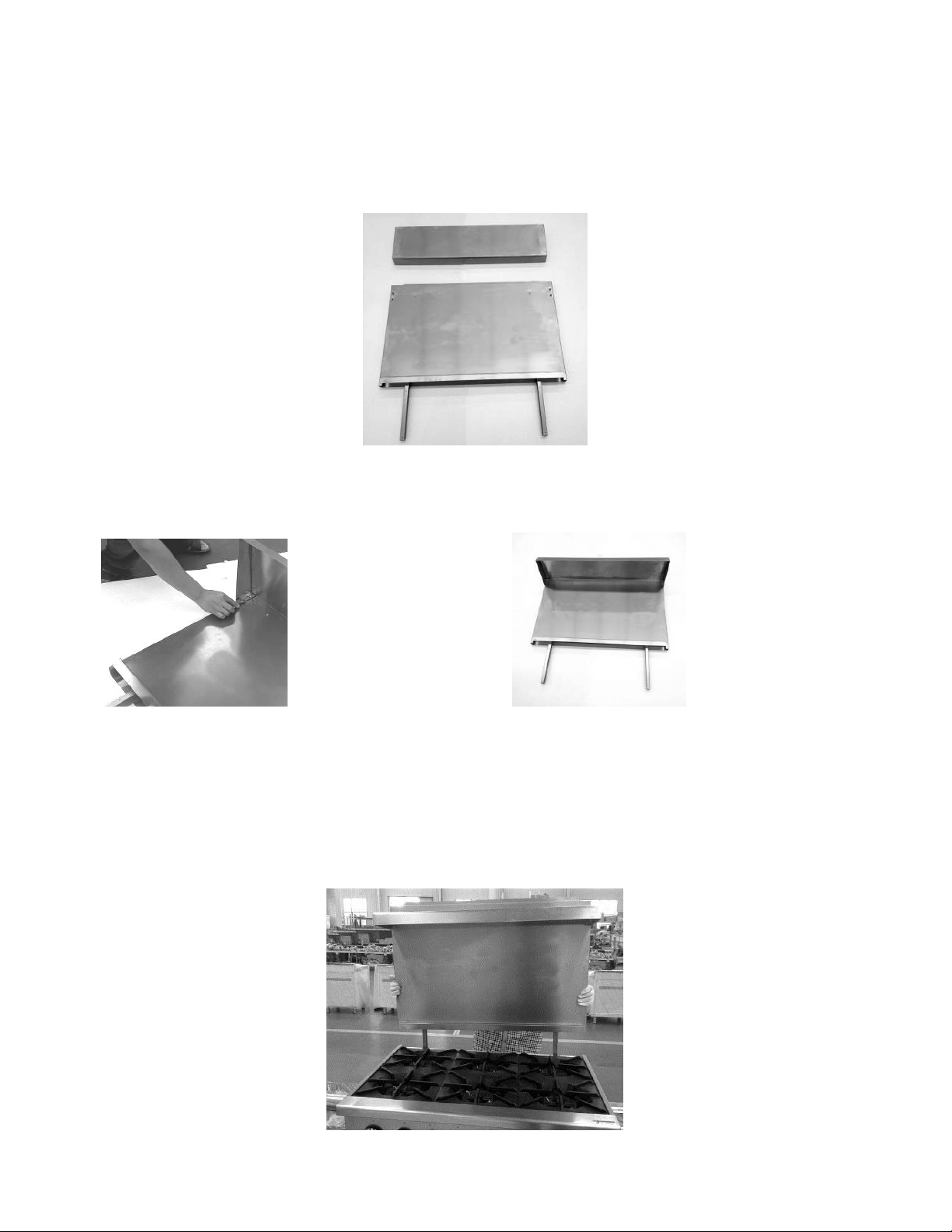
The standard Restaurant Range is equipped with a 23" (584 mm) high backsplash and shelf.
1. Remove the backsplash components from the crating materials.
2. Assemble the required components as shown in Fig’s. 2 and 3 and 4.
3. Tighten the four screws to secure the shelf.
4 Lift the assembly up, sliding the channels into the space provided at the rear of the
range.(Fig’s. 5).
6
Page 7

L
t
N
N
t
h
-
r
o
N
t
s
g
n
r
e
.
n
o
o
o
t
e
l
e
n
e
n
e
u
e
p
g
h
e
e
r
c
o
k
o
r
k
e
w
e
s
4. Install
LEVELIN
Checkth
rack(s).
Toadjus
four #10 s
G
eleveling
evelfront
theleveli
eet metal
oftheran
to-backa
ng,tiltthe
crews (2 t
e.Placea
dside-to-
rangeto
each cha
levelinsid
side.
nesidea
nel leg) (Fi
theoven
d,usingc
. 6).
Fig.6
cavityacr
annelloc
sstheov
s,unscre
n
the
adjustab
Optional
mustbe
leleginse
castersfo
level.Ifflo
tasrequi
rthisrang
rsurface
Fig
ed.Repea
areofth
isnotleve
7
thisproc
non-adj
,therang
dureasn
stabletyp
willexpe
cessaryf
.Therefo
iencecoo
reachleg.
e,thefloo
ingprobl
r
ms.
GASCO
CAUTIO
resistan
NECTIO
:Allgas
totheac
S
supplyco
ionofpr
nections
panegas
andany
s.
7
ipejoint
ompound
usedmu
tbe
Page 8

Each range is factory-equipped for the type gas specified on the rating plate. The installation
gas connection is a
3
/4" (19 mm) 14 FPT ANSI schedule #40 standard pipe. Connect gas
supply. Make sure the pipes are clean and free of obstructions. Codes require that a gas
shutoff valve be installed in the gas line ahead of the range. Standard ranges are equipped
with fixed burner orifices which coincide with installation elevation. Install the gas pressure
regulator.
Before installing, ensure that regulator supplied agrees with rating plate gas supply.
The gas pressure regulator is NOT factory installed. The regulator for this gas type is
sealed within a plastic bag attached to the oven rack inside the oven cavity. This
regulator must be field installed by a qualified installer.
Natural gas regulators are preset for 5" W.C. (Water Column) (.99 kPa); propane
gas regulators for 10.0" W.C. (2.5 kPa)
1. Locate
3
/4" (19 mm) gas connection pipe extending from rear of range.
2. Cover pipe threads with leak sealant.
3. Screw regulator hand-tight onto pipe with regulator arrow pointing towards range body
back (Fig. 7).
4. Using pipe wrench, tighten regulator securely in an upright position (Fig. 7).
The arrow on the regulator shows the direction of the gas flow. The pressure regulator
must be mounted horizontally to ensure proper preset outlet pressure. If the regulator
is installed in any other position, the outlet pressure must be reset for proper
operation.
A leak limiter is supplied with every regulator to allow excess gas pressure to escape.
Do not obstruct leak limiter on gas pressure regulator, as obstruction may cause
regulator to malfunction.
WARNING: PRIOR TO LIGHTING, CHECK ALL JOINTS IN THE GAS SUPPLY LINE
FOR LEAKS. USE SOAP AND WATER SOLUTION. DO NOT USE AN OPEN FLAME.
After piping has been checked for leaks, all piping receiving gas should be fully purged to
remove air.
Before operation, verify thermocouple is securely seated in the safety valve. The
thermocouple should be tightened a
1
/4 turn past finger tight. DO NOT OVERTIGHTEN.
Over-tightening may damage the thermocouple or safety magnet.
8
Page 9

TESTING THE GAS SUPPLY SYSTEM
When gas supply pressure exceeds
valve must be disconnected from the gas supply piping system.
When gas supply pressure is 1/2 psig(3.45kPa) or less, the range should be isolated from
the gas supply system by closing its individual manual shutoff valve until the range is
ready for start-up.
FLUE CONNECTIONS DO NOT obstruct the flow of flue gases from the flue located on the
rear of the range. It is recommended that the flue gases be ventilated to the outside of the
building through a ventilation system installed by qualified personnel.
From the termination of the flue to the filters of the hood venting system, a minimum
clearance of 18" (457 mm) must be maintained.
Information on the construction and installation of ventilating hoods may be obtained from
the standard for the "Removal of Vapors from Commercial Cooking Equipment”, NFPA No.
96 (latest edition), available from The National Fire Protection Association, Batterymarch
Park, Quincy, MA 02269.
1
/2 psig (3.45 kPa), the range and its individual shutoff
OPERATION
WARNING: THE RANGE AND ITS PARTS ARE HOT. BE VERY CAREFUL WHEN OPERATING,
CLEANING OR SERVICING THE RANGE.
CONTROLS
THERMOSTAT DIAL
Allows operator to regulate oven temperature from low to 500° F (260° C)
(OPTIONAL) GRIDDLE BURNER KNOB
Regulates gas flow to the griddle. To increase heat, turn knob counterclockwise, to decrease
heat, turn knob clockwise.
BEFORE FIRST USE
Griddle Seasoning (
CAUTION: This griddle plate is steel, but the surface is relatively soft and can be scored
or dented by the careless use of a spatula or scraper. Be careful not to dent, scratch, or
optional models
)
gouge the plate surface. Do not try to knock off loose food that may be on the spatula
by tapping the corner edge of the spatula on the griddle surface.
A new griddle surface must be seasoned to do a good cooking job. The metal surface of the
9
Page 10

griddle is porous. Food tends to get trapped in these pores and stick; therefore, it is
important to “season” or “fill up” these pores with cooking oil before cooking. Seasoning
gives the surface a slick, hard finish from which the food will release easily.
To season, heat griddle top section at a low burner setting. Pour one ounce of cooking oil
per square foot of surface over the griddle top section. With an insulated cloth, spread the
oil over the entire griddle surface to create a thin film. Wipe off any excess oil with an
insulated cloth.
Repeat this procedure 2 to 3 times until the griddle has a slick surface.
LIGHTING AND SHUTTING DOWN PILOTS
All adjustment procedures associated with pilot lighting must be performed by an
authorized vender installation or service person.
Manual GRIDDLE
1. Turn main gas supply ON.
2. Wait 30 seconds and, using a long lighter, light the hot top or griddle top pilot
3. If pilot fails to light, turn main gas supply OFF. Wait 5 minutes and repeat the above
procedures.
4. Turn one hot top or griddle top burner valve ON to remove air from the gas line. Turn
burner valve OFF when gas begins to flow.
Nightly Shutdown
1. Turn burner valve OFF; pilot will remain lit.
Complete Shutdown
1. Turn burner valve OFF; pilot will remain lit.
2. Turn main gas supply OFF.
Thermostat GRIDDLE
1. Turn main gas supply ON.
2. Locate Pilot lighting door on front of unit to left of red pilot lighting button.
10
Page 11

3. Open door and Insert long lighter.
4. Press and hold red pilot button while lighting pilot. Once pilot is lit hold button for 30
seconds.
5. Release button. Pilot should remain on.
6. Close door.
7. If pilot fails to light, turn main gas supply OFF. Wait 5 minutes and repeat the above
procedures.
8. Turn one hot top or griddle top burner valve ON to remove air from the gas line. Turn
burner valve OFF when gas begins to flow.
9. Nightly Shutdown
10. Turn burner valve OFF; pilot will remain lit.
11. Complete Shutdown
12. Turn burner valve OFF; pilot will remain lit.
13. Turn main gas supply OFF.
OPEN TOP BURNERS
1. Turn main gas supply ON.
2. Wait 30 seconds and, using a taper, light the open top pilot
3. If pilot fails to light, turn main gas supply OFF. Wait 5 minutes and repeat the above
11
Page 12

procedures.
4. Turn one open top burner valve ON to remove air from the gas line. Turn burner OFF
when gas begins to flow.
Nightly Shutdown
1. Turn burner valve OFF; pilot will remain lit.
Complete Shutdown
1. Turn burner valve OFF; pilot will remain lit.
2. Turn main gas supply OFF.
GRIDDLE (
1. Turn main gas supply ON. Wait 30 seconds and, using a taper, light broiler/griddle
2. If pilot fails to light, turn main gas supply OFF. Wait 5 minutes and repeat Steps 1 and
3. Turn burner valve ON to purge air from the lines. Turn burner valve OFF when gas
Nightly Shutdown
1. Turn burner valve OFF; pilot will remain lit.
Complete Shutdown
1. Turn burner valve OFF; pilot will remain lit.
2. Turn main gas supply OFF.
STANDARD OVEN LIGHTING AND SHUTDOWN INSTRUCTIONS NOTE:
Light open top/griddle pilots before lighting oven pilot.
optional models
pilot.
2.
begins to flow.
)
1. Turn thermostat to the “OFF” POSITION.
2. Remove the lower panel.
3. Depress the red button on the safety valve and light the pilot through the observation
area.
4. Hold down the red button for at least 30 seconds.
5. When button is released, pilot should remain lit.
6. Replace lower panel.
7. Turn thermostat to desired temperature.
12
Page 13

8. If the pilot becomes extinguished, Wait 5 Minutes, then repeat the above procedure.
Nightly Shutdown
1. Turn oven thermostat OFF.
Complete Shutdown
1. Turn oven thermostat OFF.
2. Turn main gas supply OFF.
RACK ARRANGEMENT -STANDARD OVEN
The standard oven has three rack positions and is supplied with one two oven racks.
Additional racks may be obtained through a vender parts depot.
INSERTING AND REMOVING RACK
The oven rack has a stop to keep the rack from being pulled all the way out when unloading
product. To install rack, place rack alongside of top of side liner runners and slide rack
completely to the rear of the oven compartment until rack drops
into place
To remove rack, reverse the procedure above by raising rear of oven rack stop above runner
and pulling rack forward.
PREHEATING
Standard Oven Turn thermostat control to the desired cooking temperature and preheat
oven for 25 minutes. To save on gas consumption, do not operate oven at maximum heat
when it is not necessary. Turn thermostat down to 250°F (121°C) or OFF when oven is not in
use or during idle cooking periods.
Griddle (
Turn the three manual gas valve knobs to full ON. After preheating for 5 minutes, turn valves
down until desired flame or heating level is achieved. Position the removable broiler grid
into one of the two slide positions, depending on which will achieve the proper product
results.
CLEANING
Do not use scouring powder or abrasives anywhere on this range
optional models
)
Clean only using a soft cloth and mild detergent solution.
13
Page 14

Page 15

Page 16

36”Range parts
Key
Part Number
Q’ty
Description
1
PT-100105
1
6B back splash
2
1
Shelf board
3
1
Front table
4
6
Knob
5
1
Oven thermostat knob
6
1
Oven door
7
2
Oven door hinge
8
1
Oven radiant plate
9
4
Caster set for 36"range
10
2
Chimney pillar support beam
11
1
Front panel for 6B range
12
1
Mylar for 6B range
13
1
Oven shelf bracket left
1
Oven shelf bracket right
14
4
6"adjustable leg
15
1
Drop pan for 6B range
16
2
Oven shelf for 6&10 burner use
17
1
Oven drip pan 36"
PT-301110405
PT-03900267
PT-100103
PT-4000391
PT-2660002
PT-20228062002
PT-303123917
PT-400040
PT-400041
PT-302090048
PT-20228055008
PT-400050
PT-20228055011
16
Page 17

TROUBLESHOOTING GUIDE
PROBLEM
CAUSES
1. Too much bottom heat
1a. Too low temperature
1b. Side burning
1c. Too much top heat
a) Insufficient ventilation
b) Improper fluing
c) Improper thermostat bypass setting
d) Thermostat out of calibration
e) Fluctuating gas pressure
2. Uneven bake side to side
a) Not level side to side
b) Oven burner, bottom or baffles improperly installed
c) Warped pans
3. Uneven bake front to rear
a) Overactive flue
b) Not level front to back; check casters and legs
c) Door not closing properly
4. Dried out products
a) Too low temperature (overcooking)
b) Too long baking time
c) Thermostat calibration
5. Pilot outage
a) Pilot flame to low
b) Restriction in pilot orifice
c) Problem with shutoff valve
d) Possible fluing problems
e) Low pressure
f) Improper gas line sizing
g) Burner box cover not properly installed
h) Oven cavity requires resealing
TOP BURNER OPERATION
1. Improper burner combustion
Excessive valve handle temperatures
Sticking top burner valves
a) Improper ventilation
b) Poor door fit
c) Oven door left open
d) improper use of excessively large pans or pots
2. Poor ignition
a) Insufficient input
b) Poor air-gas adjustment
c) Restriction in pilot orifice
d) Restriction in main burner ignition port
STANDARD OVEN RESTAURANT RANGE
OVEN
17
Page 18

Conversion Kit Instructions for the
6. Replace the orifice, burner and grate
Note: Unit Number on side of orifice fittings
4, Adjust air shutter from half open to full
WARNING
manufacturer’s instructions supplied with the kit.”
Gas restaurant ranges
This conversion kit shall be installed by a qualified service agency in accordance with the
manufacturer’s instructions and all applicable codes and requirements of the authority having
jurisdiction. If the information in these instructions is not followed exactly, a fire, an explosion or
production of carbon monoxide may result causing property damage, personal injury or loss of life.
The qualified service agency is responsible for the proper installation of this kit. The Installation is not
proper and complete until the operation of the converted appliance is checked as specified in the
Range Conversion Kit Instructions
Do not attempt gas conversion by yourself. Gas conversion of your unit is to
be made by a certified/licensed technician.
CONVERSION
Instructions are for conversion from Natural Gas to Propane (L.P.) on 24” & 36” models. The conversion
should be done before connecting the unit to the gas supply. Units are shipped from the factory
equipped for use on natural gas. Parts necessary for L.P. (liquid propane) are provided with the unit.
Please refer to page 5 the orifice size list when you do gas conversion..
Turn off the main gas supply before doing any maintenance.
1. Remove the grate 2. Remove the top burner.
3, Screw out top burner air shutter screw
5, Remove orifice.
7. Remove the drop pan, unscrew nut
of oven burner 8 .Incline the burner, expose orifice of oven
open, then screw in, ensure fix well.
18
Page 19

9. Replace the orifice fittings into the valve.
Pictured is the plastic insert. Pull off insert
attached to the octagon cap head.
13.1,
Regulator convert for 24”range &36”range
L.P. Position of
to L.P.
10, Screw out oven burner air
shutter screw
12, Replace orifice and oven
burner
11, Adjust oven burner air shutter from half open
to full open. then screw in, ensure fix well
and 48”range series only
Before installing the included convertible regulator,
unscrew the octagon cap. You can read (NAT) on the
plastic insert attached to the head of the cap; flip it
over and snap back in place.
insert. Regulator
is now converted
from octagon cap and reverse the plastic
insert position so that the L.P. position is
13.2, Regulator convert for 60”range
change the part from R500 Nat 3”-6”W.C to R500 LP 11”W.C.
14. Continue with installation.
15. Attach gas conversion label on appliance, the position below.
Gas conversion label
The position for gas conversion
16. Completed gas conversion.
19
Page 20

TM
WARRANTY
Patriot warrants its equipment against defects in materials and workmanship, subject to the following conditions:
Patriot gas equipment is warranted for one (1) years, effective from the date of purchase by the original owner. A copy of the original
receipt or other proof of purchase is required to obtain warranty coverage. This warranty applies to the original owner only, and is not
assignable.
The stainless steel fry tank has a ve (5) year limited tank warranty. If during the rst year, the tank is found to have a leak and is
veried by an authorized service company, the entire fryer will be replaced. During years two through ve, a new tank will be given.
Should any product fail to function in its intended manner under normal use within the limits dened in this warranty, at Patriot’s
discretion, such product will be repaired, replaced with a refurbished unit, or replaced with a new unit by Patriot, after defective unit has
been inspected and defect has been conrmed. Patriot does not assume any liability for extended delays in replacing any item beyond
its control. This warranty does not apply to rubber and non-metallic synthetic parts that may need to be replaced due to normal usage,
wear or lack of preventative maintenance.
This warranty covers products shipped into the 48 contiguous United States, Hawaii, and metropolitan areas of Alaska and Canada.
Warranty coverage on products used outside the 48 contiguous United States, Hawaii and metropolitan areas of Alaska and Canada
may vary.
The following conditions are not covered by warranty:
• Equipment failure relating to improper installation, improper utility connection or supply and problems due to improper ventilation.
• Equipment that has not properly been maintained, damage from improper cleaning, and water damage to controls.
• Equipment that has not been used in an appropriate manner, or has been subject to misuse, neglect, abuse, accident, alteration,
negligence, damage during transit, delivery or installation, re, ood, riot, or act of God.
• Equipment that has the model number or serial number removed or altered.
• Equipment on which the security seal has been broken.
If the equipment has been changed, altered, modied, or repaired without express written permission from Patriot, then the
manufacturer shall not be liable for any damages to any person or to any property, which may result from the use of this equipment
thereafter.
This equipment is intended for commercial use only and this warranty is void if equipment is used in other than a commercial application.
For warranty issues
proof of purchase ready. For non-warranty related issues call 800-458-5593.
“THE FOREGOING WARRANTY IS IN LIEU OF ANY AND ALL WARRANTIES EXPRESSED OR IMPLIED INCLUDING ANY
IMPLIED WARRANTY OF MERCHANTABILITY OR FITNESS FOR PARTICULAR PURPOSES AND CONSTITUTES THE ENTIRE
LIABILITY OF PATRIOT. IN NO EVENT DOES THE LIMITED WARRANTY EXTEND BEYOND THE TERMS STATED HEREIN.”
and technical support call Patriot Cooking at 888-585-9440. Please have your model number, serial number and
Please fill out and return the warranty registration card below to the address provided
WARRANTY
REGISTRATION
CARD
MAIL CARD
IMMEDIATELY
This card must be
mailed immediately
after installation date
for warranty to be in
effect.
or register online at Patriotcooking.com
PATRIOT COOKING 5130 Executive Boulevard Fort Wayne, IN 46808 Attn: Warranty Registration
(Name of Busines) (Dealer Purchased From)
(Address) (City) (State) (Zip Code)
(Model Number) (Serial Number)
This is to inform that I, ___________________________________________________________________
(Please print name of individual who owns the business)
have had the above installed in my place of business __________________________________________
(Date of Purchase)
(Contact Phone Number) (Contact E-mail) (Signature of individual who owns Business)
The above warranties are in effect from this installation date, or 90 days, which ever comes rst.
 Loading...