

Paso Sound WPSS150M User Manual
WPSS150M
Portable Sound System
Operation Manual
Manual
OM 237
REV. 1.0
CAUTION
TO RE D UC E THE RI S K OF FIR E OR
ELE C T R IC SHOCK. DO NOT EX POSE
THIS APPLIANCE TO RAIN OR MOISTURE.

WPSS150M Operation Manual
Congratulations and thank you for purchasing this all-in-one portable sound system. To
ensure a trouble-free operation, please read the manual thoroughly to fully understand its
controls and functions.
WPSS150M can be installed with up to 4 receiver modules, among which one can be
transmitter module. The wireless receiver/transmitter module can be in either UHF or VHF
band and is a PLL synthesized type with 100 preset frequencies.
Conguration :
All versions of WPSS150M series come equipped with the following :
1. Switching power supply.
2. 1~4 or no wireless receiver/transmitter module(s).
3. 1~4 transmitters, either handheld or bodypack transmitter (except version with no
module installed).
Optional accessories :
1. Weather proof dust cover.
2. Tripod stand
3. Companion powered speaker .(WPSS150S)
4. Companion passive speaker.(PASS100)
5. Wired microphone.
6. Battery charger. (XC33)
Remarks:
Manufacturer reserves the rights to change the above combinations without prior notice.
-1-
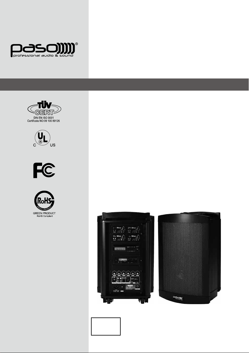
WPSS150M (Master, Basic conguration)
A
A,B&D. Receiver modules
C
C. Transmitter module
B
D
1. Mic-1 volume ctrl
2. Mic-2 volume ctrl
3. Line-in volume ctrl
4. DVD volume ctrl
1
2 3 4 5 6
5. Tone ctrl (bass)
6. Tone ctrl (treble)
7. Mic-1 input
8. Mic-2 input
9. Line in/out
10. USB connector
11. Voice priority
12. Battery low led
13. Charging indicator
14. Battery power led
15. Battery test button
87 9
19
141615
10
12
13
11
17
18
16. Fuse
17. 24~32V DC input
18. External speaker
19. Power switch
-2-

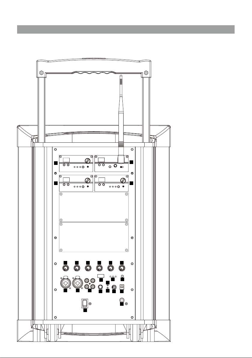
WPSS150M (Master, CD/USB player & Digital Recorder player version)
CD player:
1. LCD display
2. Play/pause
3. Stop
4. Skip
5. Eject
6. CD selector
7. USB selector
8. Folder skip
9. IR led
1
19
18
17
16
2 3 4 5
6 87 9
20
15
111210
13
14
11
10
193 24576
8
10. USB input
11. Power/volume
Digital recorder:
1. Play/Pause
2. Stop
3. SD/USB selector
4. Track number button "1"
5. Track number button "10"
6. Track number button "100"
7. A→B play section
8. Program/Repeat
9. Forward
10. Reverse
11. Folder selector
12. Volume control
13. USB 2.0 input
14. SD card input
15. Copy
16. Record
17. Infrared detector
18. Power on/off
19. Delete
20. LCD display
-3-
WPSS150M (Master, DVD player version)
1112 10141513
DVD player
1. Video signal output
193 2457 6
8
2. Power on/off
3. Eject
4. Stop
5. Up
6. Down
7. Play/Pause
8. USB 2.0 input
9. Infrared detector
10. Function selector
11. N/P
12. Cue
13. Rev
14. Repeat
15. LCD display
-4-

WPSS150S (LIMITED AVAILABILITY)
The WPSS150S is an active (powered) speaker unit with built-in switching power supply
as well as rechargeable batteries, complete with similar charging circuit as that of the
WPSS150M Master unit.
It is an extended and indispensable member of the Soundcaster Audio Link system.
A. Slot for receiver module
A
B
B. Slot for receiver/transmitter module
19
18
11
12
20
11. Speaker output (switched)
13
14
15
16
17
12. Speaker output
13. 24-32v DC input
14. Fuse
15. Battery low indicator
16. Battery status indicator
17. Charging indicator
18. Slave input
19. Slave output
20. Slave volume ctrl
-5-
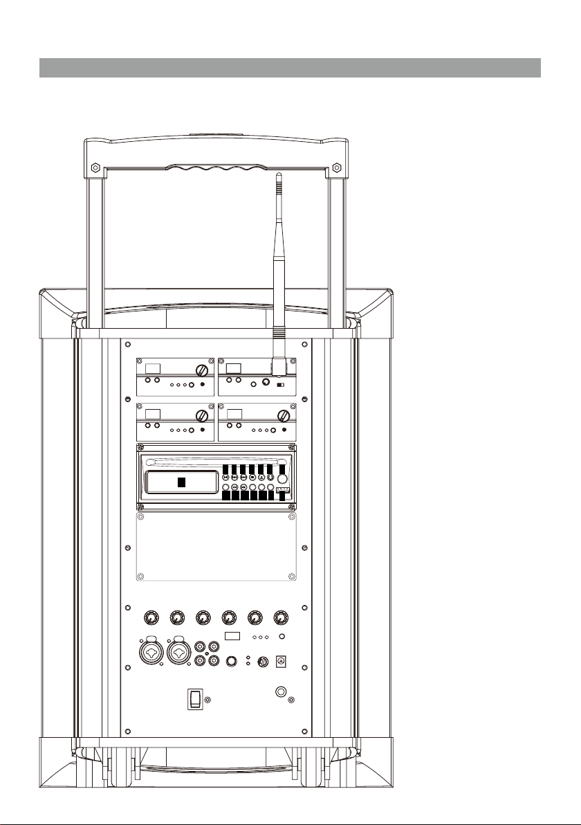
PASS100 Speaker
The PASS100 Speaker is a passive companion speaker for the WPSS150M series.
It is for connection to the switched or unswitched speaker outs of the WPSS150M (Master)
or the PASS100 Slave units.
22 23
22. Speaker input
23. Speaker output
-6-
Operating procedures
After unpacking the unit for the rst time, please charge the unit for about 4-5 hours before
any operation. This is absolutely necessary as the built-in rechargeable battery might have
been discharged naturally due to long shipment and storage time, even though it has been
fully charged in the factory prior to shipment.
To operate this portable sound unit, switch on the main POWER switch, the GREEN LED
above it will glow. However, if the RED LED also glows at the same time, it means the
battery is getting weak and a recharge of the battery is necessary. To know the battery
status, its remaining level can be detected by pressing the battery status button and the
LEDs can tell whether the batteries need to be charged. The red LED lighting implies the
power is too low, the green one implies enough power and the yellow one means the power
level is in between.
The main POWER switch does NOT switch on the Wireless receiver module and Tape/CD
Player/Digital Recorder as each of them has dedicated Power / Volume control switch on
its panel. To operate each of them, you must switch them on accordingly.
Operating the dynamic wired microphone.
To use a cable microphone, simply plug it into any MIC IN socket. The mic sockett accepts
both phone and Cannon jack. Rotate the dedicated volume control knob and master
volume control, amplied sound could be heard from the speaker when voice is spoken
into the cable microphone.
When a full range high delity sound is emphasized, the mode selector should be put to
MUSIC. For vocal frequencies where better clarity and projection is emphasized, put the
mode selector to SPEECH and this will produce more mid-range frequency.
Operating the Wireless Microphone System.
To operate the wireless system, just switch on the power/volume control on the module
panel and the matching transmitter. Please have the channel setting on both the transmitter
and receiver module be the same before operation. Please as well make sure that master
volume control is set to minimum level before turning the unit on, especially working on
a wireless version! Set the Master volume control to the mid position. Rotate the volume
control knob on receiver panel clockwise to the desired levels. When voice is spoken into
the microphone, amplied sound should be heard over the built-in speaker.
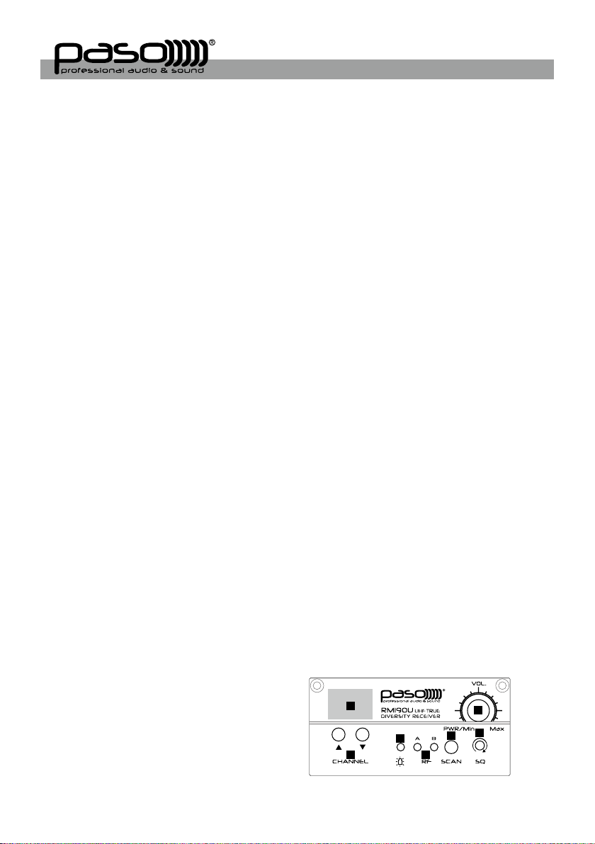
RM190U receiver module
1. Channel Indicator
2. Power switch/volume control
3. Channel Selector
4. Transmitter battery weak indicator
5. Diversity A/B Indicator
6. SCAN
1
4
3
5
2
7
6
7. Squelch control
-7-
First turn on the Power of the main unit. Then turn on the individual power of the RM190U
receiver module. Select a desired channel by pressing the ▲ or ▼ button and the
corresponding channel on the Transmitter.
When transmitter is turned on, either A or B diversity indicator will ash to indicate that
signal has been received. Turning the volume control in clockwise direction can increase
the audio output. Once the power volume on the transmitter is too low, the LED indicator on
this panel grow will grow to remind.
Frequency scanning
It is the automatic scan function key. To perform the scan function, the transmitter must be
switched off. Once the key is being pressed, the unit will do an auto scan and the next
clean channel will be displayed. Change the transmitter channel setting to this setting for
an interference- free operation.
Squelch(SQ) setting
When a channel is in use and undesired interference signal is received, turn the SQ
in clockwise direction to make the receiver less sensitive and thus less susceptible to
interference. If this still does not solve the problem, it means this frequency is not applicable
at current position. Please switch over to the next channel.
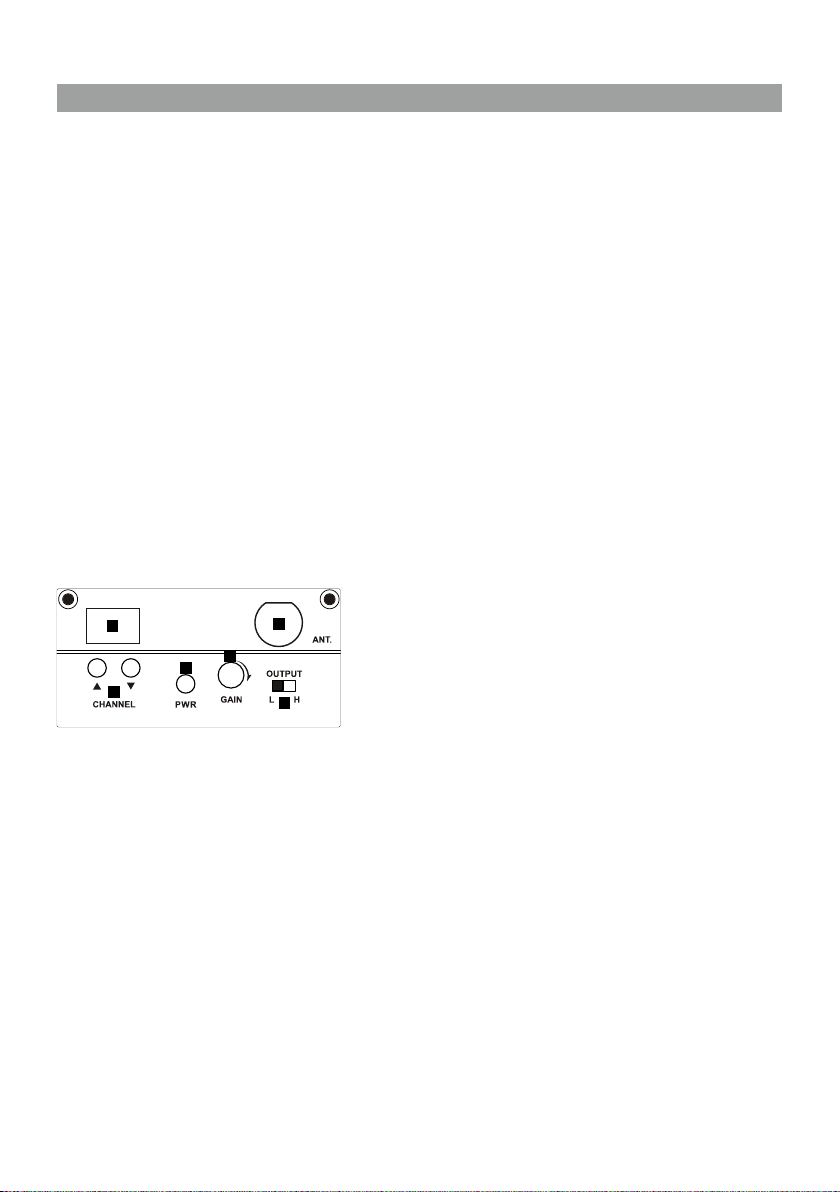
TM190 Transmitter module
1
4
3
2
5
6
1. Channel indicator
2. Antenna socket(TNC type)
3. Channel selectors: Press ▲(up)▼(down) to increase/decrease channel number. Please
select a non-interfering frequency channel to those used in the receiver modules.
4. Power on/off
5. Audio sensitivity: Clockwise to increase its sensitivity level and anticlockwise to reduce.
6. Output power switch. L for LOW output power and H for high output power. LOW output
power will reduce the RF transmission distance and HIGH output power will extend the
possible RF transmission distance.
However, if TM190 is installed in portable ampliers, HIGH output power will reduce
more operation time than LOW output power since it requires more power for longer RF
transmission.
-8-

Operating the Digital In
WPSS150M can be the speaker of an external auidio source by connecting them using a
USB cable (male-to-male type). The MP3 les can be played through WPSS150M when
operating the tracks on the PC.
Voice Priority operation
Voice Priority operation is only necessary when CD/DVD/MP3 is playing.
When the Voice Priority switch is ON, the ducking function will be activated. While the
music is playing, a voice input from either a Wired or Wireless Microphone will temporary
override and turn down the volume of the background music and voice could be heard
clearly.
Background music will return to its original setting when no audio input is entering the
microphone for a certain time. However, if the microphone is not switch off, the reentering
of music into the microphone will also activate the voice priority function. So, Voice
priority is best operated using microphones with on / off switch.
However, in an aerobic operation, Voice Priority should NOT be activated !
-9-
 Loading...