


® |
Manual |
Integrated Amplifiers OM 167
 PROFESSIONAL AUDIO & SOUND
Installation Manual
and Operating Instructions
4 Channel - 2 Zone - VOX -MOH -
Phone Interface
T3115BGM - 15 Watt RMS
T3130BGM - 30 Watt RMS
IMPORTANT NOTE: THIS OPERATING MANUAL IS PROVIDED AS AN INSTALLATION AND AS AN OPERATING AID. PASO SOUND PRODUCTS, INC. DOES NOT ASSUME ANY RESPONSIBILITY AS TO ITS ACCURACY AND SHALL NOT BE LIABLE IN TORT OR CONTRACT FOR ANY DIRECT CONSEQUENTIAL OR INCIDENTAL LOSS OR DAMAGE ARISING FROM THE INSTALLATION, USE OR INABILITY TO USE THIS PRODUCT.
3000 Series
TO REDUCE THE RISK OF FIRE OR ELECTRIC
CAUTION ! SHOCK DO NOT EXPOSE THIS APPLIANCE TO
WATER, RAIN OR MOISTURE
Innovation through technology since 1931
|
|
|
REV. 4.0 |
© copyright Paso Sound Products, Inc. 2005 |
Specifications are subject to change without notice |
|
|
|
|
|
|


 ®
®
 PROFESSIONAL AUDIO & SOUND
INTEGRATED AMPLIFIERS
DESCRIPTION AND APPLICATIONS
4 Channel Inputs - 2 Zone Outputs
Wide Frequency Response
Very Low Distortion
Balanced Microphone Input
Phantom Power on MIC Input with Selector
Transformer Balanced Phone Paging Input
Telephone Input Level Control
Auxiliary Input With Stereo Summing
Auxiliary Input Attenuator
Balanced Program Input
Independent Input Controls
Bass and Treble Controls
VOX - Voice Activated Muting
Direct Muting or Unmuting
600 ohm and 8 ohm 1 Watt Music on Hold Amplifier
MOH Amplifier Source Selector
Zone 2, 1 Watt - 8 ohm Output with Separate Control
AC Accessory Outlet
8 ohm, 25 Volt & 70 Volt
Output Impedance
Rack Mounting with Optional Kit
UL 6500 Listed (US - CANADA)
|
SPECIFICATIONS |
T3115 Power Output: |
15 Watt RMS |
T3130 Power Output: |
30 Watt RMS |
Distortion: |
Less than 0.5% THD |
Frequency Response: |
20 - 20,000 Hz ± 1 db |
Inputs: |
|
Input 1 |
Microphone Balanced |
Input 2 |
Telephone Transformer Balanced |
Input 3 |
Auxiliary |
Input 4 |
Program Balanced |
Sensitivity & Z: |
|
Input 1 |
Mic=1 Mv - 250 ohm balanced |
Input 2 |
Tel=100 Mv - 600 ohm balanced |
Input 3 |
Aux=100 Mv - 47K ohm |
Input 4 |
Prog.=1 Volt - 10K ohm balanced |
Hum & Noise: |
Mic -70 db, Aux/Pgm -75 db |
Telephone Input: |
600 ohm Transformer balanced |
Music on Hold Output: |
600 ohm-1 Volt Transf. balanced |
Zone 2 Output: |
1 Watt-8 ohm |
Output Impedance: |
8 ohm, 25 Volt and 70 Volt line |
Controls: |
|
Front Panel: |
MIC Volume, AUX Volume, |
|
PROG Volume, Bass, Treble |
Rear Panel |
PHONE Level, AUX Attenuator, |
|
MOH & ZONE 2 Level Control |
Phantom Power: |
On MIC Input w/internal jumper |
MOH Source: |
AUX or PROG w/internal jumper |
Tone Control Action: |
+/-10 db at 100 Hz and 10 K hz |
VOX: |
Voice Activated Muting |
|
MIC/PHONE mutes AUX/PROG |
Muting/Unmuting: |
Mutes or Unmutes |
|
MIC/AUX/PROG |
Rack Mounting: |
Optional Rack Kit |
Power Requirement: |
117 Volt, 50-60 Hz |
Power Consumption: |
T3115 = 570 VA, T3130 = 600 VA |
AC Accessory Outlet: |
500 W Max. Unswitched |
Terminations: |
Screw Terminals, RCA Jacks |
Housing Finish: |
Black |
Dimensions: |
10.5"W., 9.5"D., 3.5"H. (267X242X89 mm) |
Net Weight: |
T3115 = 8 Lbs (3.7 Kg) |
|
T3130 = 11 Lbs (5.0 Kg) |
UNPACKING |
|
ACCESSORIES |
|
|
|
Immediately upon receipt of the amplifier, inspect the unit and shipping container for indications of improper handling or in transit damage. The equipment was carefully inspected and tested before leaving the factory. Notify the Transportation Company immediately if any damage is found. ONLY THE CONSIGNEE CAN FILE A CLAIM WITH THE CARRIER FOR DAMAGE DURING SHIPMENT. Be sure to save the carton and packing material as evidence of damage for the shipper inspection. DO NOT SHIP the unit back to the factory unless authorized by the factory.
IN TRANSIT DAMAGES ARE NOT COVERED BY THE PASO WARRANTY.
27/3500 - Standard 19” Rack Mounting Kit. Black finish. Complete with hardware
PAGE 2 |
© copyright Paso Sound Products, Inc. 2005 |
Specifications are subject to change without notice |
T3115/3130/3160BGM |


 ®
®
 PROFESSIONAL AUDIO & SOUND
INTEGRATED AMPLIFIERS
IMPORTANT SAFETY INSTRUCTIONS
READ BEFORE OPERATING
BEFORE OPERATING THE AMPLIFIER, BE SURE YOU FULLY UNDERSTAND ALL INSTRUCTIONS AND FEATURES OF THE UNIT.
1)Read these instructions carefully.
2)Keep these instructions.
3)Heed all Warnings.
4)Follow all instructions.
5)DO NOT use this apparatus near water.
6)Clean ONLY with a damp cloth.
READ BEFORE OPERATING
outlet, consult an electrician for replacement of the obsolete outlet.
12)Use only the attachments and accessories specified in this manual.
13)If a cart is used, use caution when moving the cart/apparatus combination to avoid injury from tipover.
14)Unplug this apparatus during lighting storms or when unused for long periods of time.
7)DO NOT block any of the ventilation openings. 15) Refer all servicing to qualified service personnel.
Install in accordance with the instructions provided.
8)DO NOT install near any heat sources such as radiators, stoves, or other apparatus (including amplifiers) that produce heat.
9)DO NOT mount amplifier into a container or a closed unventilated closet while operating.
10)DO NOT place any object or accessory equipment such as Tuners, Mixers, Cassette Decks, etc. on top of the amplifier. Obstructing or closing the cabinet ventilation openings may cause overheating.
11)DO NOT defeat the safety purpose of the polarized or grounding type plug. A polarized plug has two blades with one wider than the other. A grounding type plug has two blades and a third grounding prong. The wide blade and or the third prong is provided for your safety. When the provided plug does not fit into your
Servicing is required when the apparatus has been damaged in any way, such as power supply cord or plug is damaged, liquid has been spilled or objects have fallen into the apparatus, the apparatus has been exposed to rain or moisture, does not operate normally, or has been dropped.
16)DO NOT replace fuses unless power cord is removed from the AC wall outlet.
17)DO NOT install accessories unless the power cord is removed from the AC wall outlet.
TO REDUCE THE RISK OF FIRE OR ELECTRIC SHOCK DO NOT EXPOSE THIS APPLIANCE TO WATER, RAIN OR MOISTURE
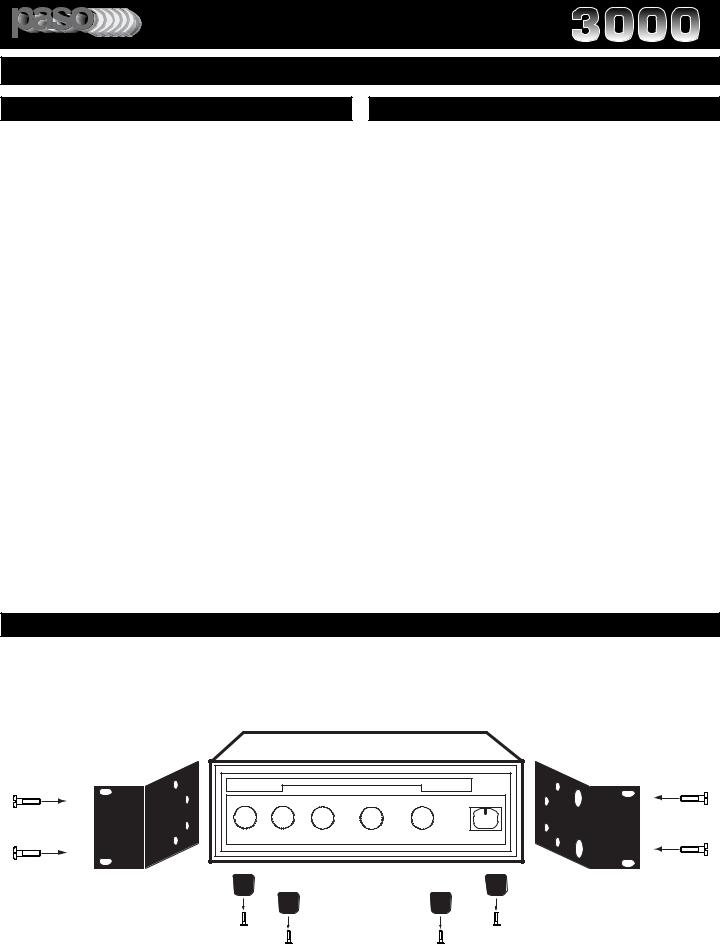
RACK MOUNTING
A)Procure the optional accessory Rack Mount Kit.
B)Turn amplifier up side down and remove the four rubber feet by unscrewing the four holding screws.
C)Remove three screws on each side of the amplifier holding the amplifier cover.
D)Install the rack kit brackets by using the self-tapping screws provided and the screws removed as per C.
Fig. 3 - Rack Kit Mounting
|
SERIES 3000 |
INTEGRATED AMPLIFIER |
|
|
|
|
|
|
|||||||
|
|
|
|
|
|
|
|
|
|
|
|||||
|
5 |
|
|
|
5 |
|
|
5 |
|
|
0 |
|
0 |
|
|
3 |
4. . |
.6 |
3 |
. |
4. . |
.6 |
.7 |
3 4. . |
.6 |
2. |
1. . |
.1 |
1. . |
.1 |
|
|
. |
.7 |
|
|
|
. |
.7 |
|
.2 |
2. |
.2 |
|
|||
2. |
|
.8 2. |
|
|
.8 2. |
.8 |
3 . |
|
.3 |
3 . |
.3 |
|
|||
1 .0. |
. 1.9 1 .0. |
. |
. 9 |
1.0. |
. 10.9 |
4. . |
. 5.4 |
4.- . |
. 5.4 |
O |
|||||
|
|
0 |
|
|
|
1 0 |
|
|
5 |
- |
+ |
5 |
+ |
|
|
|
MIC |
|
|
|
AUX |
|
|
PROGRAM |
|
BASS |
TREBLE |
POWER |
|||
3115rack mount
T3115/3130/3160BGM |
SPECIFICATIONS ARE SUBJECT TO CHANGE WITHOUT NOTICE |
PAGE 3 |


 ®
®
 PROFESSIONAL AUDIO & SOUND
INTEGRATED AMPLIFIERS
FRONT PANEL CONTROLS
SERIES |
3000 |
INTEGRATED AMPLIFIER |
|
|
|
|
|
|
® |
|||
|
|
|
|
|
|
|
||||||
|
|
|
|
|
|
|
|
|
PROFESSIONAL AUDIO & SOUND |
|
||
|
|
|
|
|
|
|
|
|
|
|
||
5 |
.6 |
5 |
.6 |
5 |
|
0 |
0 |
|
|
|||
4. . |
4. . |
4. . |
.6 |
|
1 . . |
.1 |
1 . . |
.1 |
|
|
||
3 . |
.7 |
3 . |
.7 |
3 . |
.7 |
2 . |
|
.2 |
2 . |
|
.2 |
|
2. |
. 8 2. |
.8 |
2. |
.8 |
3 . |
|
.3 |
3 . |
|
.3 |
O |
|
1 . |
.9 |
1 . |
.9 |
1 . |
.9 |
4 . |
. |
.4 |
4 . |
|
.4 |
|
0 . |
. 10 |
0 . |
. 10 |
0 . |
.10 |
-5 |
. 5+ |
-5 . |
. 5+ |
|
||
MIC |
|
AUX |
|
PROGRAM |
|
BASS |
TREBLE |
|
POWER |
|||
3115cont |
|
|
|
|
|
|
|
|
|
|
|
|
1 |
|
2 |
|
3 |
|
4 |
5 |
|
6 |
|||
|
|
Fig. 4 - Front Panel Controls |
|
1) |
MICROPHONE Input Volume Control |
4) |
Bass Control |
2) |
AUX Volume Control |
5) |
Treble Control |
3) |
PROGRAM Volume Control |
6) |
On-Off Power Switch |
REAR PANEL INPUTS - OUTPUTS
1 |
|
2 |
3 |
4 |
5 |
6 |
7 |
CAUTION; TO REDUCE THE RISK OF FIRE OR SHOCK DO NOT |
ATTENTION: POUR REDUIRLES RISQUES D© INCENDIE OU |
|
|
|
AUX |
|
|
DE CHOC ELECTRIQUE, NE PAS EXPOSER A LA PLUIE OU |
|
|
47K ohm 200 Mv |
|
|
||
EXPOSE THIS APPLIANCE TO RAIN OR MOISTURE. DO NOT |
L©HUMIDITE, NE PAS ENLEVER LE COUVERCLE. AUCUN |
|
|
|
|
||
|
|
|
IN PARALLEL |
|
|
||
REMOVE COVER. THERE ARE NO USER SERVICEABLE PARTS |
REGLAGE A L©INTERIEUR. POUR REPARATION |
|
|
|
|
|
|
INSIDE. REFER SERVICING TO QUALIFIED SERVICE PERSONNEL. |
CONSULTERUNE PERSONNE QUALIFIEE |
|
|
|
|
|
|
|
T3115BGM |
MOH |
OUTPUT |
L |
|
|
TEL OUTPUT |
117V 60 Hz |
1 Volt |
1 WATT |
LEVEL |
|
|
||
|
|
600 ohm |
8 OHM |
MOH OUTPUT |
|
|
LEVEL |
|
AMPLIFIER |
|
|
|
|
|
|
POWER RATING |
15 W RMS |
|
|
R |
|
AUX |
|
SUPPLY VOLTAGE |
117V 60 HZ |
|
|
|
ATTENUATOR |
||
|
|
POWER CONSUMPTION |
570 VA |
|
10K OHM |
250 OHM |
600 OHM |
|
|
|
|
|
|
|
|||
|
|
CAUTION: TO REDUCE THE RISK OF FIRE, |
|
|
1 V |
1 MV |
100 MV |
|
|
|
|
|
|
|
|
||
|
|
REPLACE ONLY WITH SAMETYPE OF |
COM 8 25V |
70V |
PROGRAM |
MIC |
TEL |
|
500 W MAX. |
FUSE. |
|
||||||
|
|
|
|
|
|
|
||
UNSWITCHED |
ATTENTION: AFIN DE |
|
|
|
|
|
|
|
|
|
GROUND |
|
|
|
|
|
|
|
|
REDUIR LE RISQUE |
|
|
|
|
|
|
|
|
D©INCENDIE, REMPLACER |
|
|
|
|
|
|
|
|
SEUL PAR UN FUSIBLE DE |
|
|
|
|
|
|
|
|
MEME TYPE. |
|
|
UNMUTE G MUTE |
G COM HOT |
G COM HOT |
G COM HOT |
|
LINE FUSE |
|
CLASS 2 WIRING ACCEPTABLE |
|
|
|
||
|
|
SER. NO. |
|
BALANCED |
BALANCED |
BALANCED |
||
|
1.6A 250 V |
|
|
|
|
|
||
|
|
|
|
|
|
|
||
|
|
3115inou |
|
|
|
|
|
|
15 |
14 |
|
13 |
12 |
11 |
10 |
9 |
8 |
|
Fig. 4A - Rear Panel Inputs and Outputs |
||
1) |
Unswitched AC Auxiliary Socket |
9) |
Balanced Microphone Input |
2) |
600 ohm MOH Output |
10) |
Balanced Program Input |
3) |
1 Watt 8 ohm Output (2nd zone or MOH) |
11) |
Mute/Unmute Terminals |
4) |
MOH Output Level |
12) |
Speaker Output |
5) |
AUX Input |
13) |
Chassis Ground Screw |
6) |
AUX Input Level Attenuator |
14) |
AC Line Fuse |
7) |
TEL Output Level Control |
15) |
AC Power Cord |
8) |
Balanced Telephone Paging Input |
|
|
PAGE 4 |
Specifications are subject to change without notice |
T3115/3130/3160BGM |


 ®
®
 PROFESSIONAL AUDIO & SOUND
INTEGRATED AMPLIFIERS
INSTALLATION AND WIRING
INPUT CONNECTIONS
CAUTION; TO REDUCE THE RISK OF FIRE OR SHOCK DO NOT |
ATTENTION: POUR REDUIRLES RISQUES D© INCENDIE OU |
DE CHOC ELECTRIQUE, NE PAS EXPOSER A LA PLUIE OU |
|
EXPOSE THIS APPLIANCE TO RAIN OR MOISTURE. DO NOT |
L©HUMIDITE, NE PAS ENLEVER LE COUVERCLE. AUCUN |
REMOVE COVER. THERE ARE NO USER SERVICEABLE PARTS |
REGLAGE A L©INTERIEUR. POUR REPARATION |
INSIDE. REFER SERVICING TO QUALIFIED SERVICE PERSONNEL. |
CONSULTERUNE PERSONNE QUALIFIEE |
117V 60 Hz |
|
T3115BGM |
|
|
|
|
AMPLIFIER |
|
POWER RATING |
15 W RMS |
|
|
SUPPLY VOLTAGE |
117V 60 HZ |
|
|
POWER CONSUMPTION |
570 VA |
|
|
CAUTION: TO REDUCE THE RISK OF FIRE, |
|
|
|
REPLACE ONLY WITH SAMETYPE OF |
COM 8 25V 70V |
|
500 W MAX. |
FUSE. |
|
|
|
|
|
|
UNSWITCHED |
ATTENTION: AFIN DE |
|
|
|
GROUND |
|
|
|
REDUIR LE RISQUE |
|
|
|
D©INCENDIE, REMPLACER |
|
|
|
SEUL PAR UN FUSIBLE DE |
|
|
|
MEME TYPE. |
|
CLASS 2 WIRING ACCEPTABLE |
LINE FUSE |
|
||
|
SER. NO. |
||
1.6A 250 V |
|
||
|
|
||
Fig. 5 Amplifier Rear Panel View
|
|
|
AUX |
|
|
|
|
47K ohm 200 Mv |
|
|
|
|
IN PARALLEL |
|
MOH |
OUTPUT |
|
L |
TEL OUTPUT |
600 ohm |
8 OHM |
MOH OUTPUT |
|
|
|
LEVEL |
|||
1 Volt |
1 WATT |
LEVEL |
|
|
|
|
|
R |
AUX |
|
|
|
|
|
|
|
|
ATTENUATOR |
|
|
|
10K OHM |
250 OHM |
600 OHM |
|
|
1 V |
1 MV |
100 MV |
|
|
PROGRAM |
MIC |
TEL |
UNMUTE G MUTE |
G COM HOT |
G COM HOT |
G COM HOT |
|
|
|
BALANCED |
BALANCED |
BALANCED |
MICROPHONE INPUT
MICROPHONE TYPE
The Microphone Input accept Low Impedance (250-600 ohm) Microphones. The Microphone may be a balanced output type (three wire) or an unbalanced output type (two wire).
PASO MICROPHONES
All PASO low impedance Microphones have a balanced output for best performance. Connect the RED lead to terminal HOT, the WHITE lead to terminal COM and the SHIELD to terminal G (see Fig. 5A).
THREE LEADS BALANCED MICROPHONE WIRING
The microphone lead color refers to Paso Microphones only. When using other microphone brand refer to instructions packed with the unit.
|
RED |
|
WHITE |
|
SHIELD |
MIC |
|
PROGRAM |
MIC |
|
UNMUTE G MUTE G |
COM HOT |
G |
COM HOT |
||
3115micbal |
|
|
|
|
|
|
|
|
|
|
|
|
|
|
BALANCED |
|
BALANCED |
|||
|
|
|
||||
Fig. 5A - Rear Panel MIC Input Terminals
TWO LEADS UNBALANCED MICROPHONE WIRING
The microphone lead color refers to Paso Microphones only. When using other microphone brand refer to instructions packed with the unit.
|
RED |
|
WHITE |
MIC |
SHIELD |
|
|
PROGRAM |
MIC |
UNMUTE |
G MUTE G |
COM HOT |
G |
COM HOT |
||
|
|
|
|
|
|
|
3115micunbal |
|
BALANCED |
|
BALANCED |
||
Fig. 5B - Rear Panel MIC Input Terminals
CAUTION
TO PREVENT POSSIBLE DAMAGE TO SPEAKERS OR THE AMPLIFIER ALL INPUT CONNECTIONS MUST BE MADE WITH THE AMPLIFIER OFF (POWER OFF).
WIRING
MICROPHONE INPUT
Attach the microphone leads to the terminal strip as per diagram in Fig 5A or Fig. 5B.
DO NOT GROUND THE MICROPHONE CABLE SHIELD TO THE CHASSIS OF THE AMPLIFIER
CABLE
BALANCED MICROPHONE
IMPORTANT NOTE: The use of an unbalanced Microphone (two leads) is not recommended. For best results in a PA Application always use a Unidirectional, Low Impedance, Balanced Microphone (three leads).
CABLE LENGTH - If the distance between the Microphone and the Amplifier Input is greater than 15 ft (4.5 m) a Balanced Microphone must be used. Use a two conductor shielded wire and connect Microphone to Amplifier as per Diagram in Fig. 5A.
MICROPHONE CABLE ROUTING - The Microphone Cable should be carefully routed. Improper Cable routing will cause spurious oscillations, regenerative noises, hum, etc. that may permanently damage the Amplifier.
Do not route cable next to power lines.
Do not route cable near or over Fluorescent Fixtures.
Do not route cable next to Speaker Wires.
Do not install cable inside Power Line Conduits.
Avoid the use of staples that may penetrate the cable.
UNBALANCED MICROPHONE
Attach the Microphone leads to the terminal strip as per diagram in Fig 5B.
Be sure the cable length does not exceeds 15 Ft. (4.5 m).
T3115/3130/3160BGM |
SPECIFICATIONS ARE SUBJECT TO CHANGE WITHOUT NOTICE |
PAGE 5 |
|


 ®
®
 PROFESSIONAL AUDIO & SOUND
INTEGRATED AMPLIFIERS
INSTALLATION AND WIRING
INPUT CONNECTIONS
MICROPHONE INPUT
USING A PUSH-TO-TALK DESK BASE MICROPHONE
Microphone paging and precedence over the AUX or PROGRAM channels may be accomplished by using a Desk Base or a Gooseneck Microphone. Wire the Microphone output leads to the MIC input terminals as per Fig. 6A.
MUTING: The Amplifier is equipped with two independent Muting Circuits:
Direct Muting by shorting the MUTE Terminals
Automatic Muting with VOX - Voice Activated Muting
For additional information on the Muting operation refer to the Muting Functions section of this Manual.
DESK BASE/GOOSENECK MICROPHONE WITH MUTING SWITCH |
|
|||||||||
MICROPHONE OUTPUT LEVEL CONTROL IS LOCATED ON THE FRONT PANEL |
||||||||||
MIC |
|
|
|
SHIELD |
|
|
|
|
|
|
|
MUTING SWITCH |
|
|
|
|
MIC |
|
|||
|
|
|
|
|
|
A |
|
B |
|
|
|
|
|
PROGRAM |
|
|
MIC |
|
|
TEL |
|
UNMUTE G |
MUTE |
G |
COM |
HOT |
G |
COM |
HOT |
G |
COM |
HOT |
micbas03 |
|
|
|
|
|
|
|
|
|
|
WIRING
Wire the Desk Base Microphone leads to the Microphone Input terminal strip as per diagram in Fig 6A. Check Microphone instructions and connect HOT LEAD (B) to Terminal HOT, COMMON LEAD (A) to Terminal COM and SHIELD LEAD to Terminal G.
DO NOT GROUND THE MICROPHONE CABLE SHIELD TO THE CHASSIS OF THE AMPLIFIER
Push to Talk Key
b50side
Fig. 6A - Rear Panel MIC Input Terminals |
Fig. 6C - Desk Base Microphone |
CONNECTING TO THE TELEPHONE PAGING SYSTEM
DMS |
DIGITAL MUSIC AMPLIFIER |
OUTPUT LEVEL |
|
TEL |
|
PEAK |
|||
DIGITAL MUSIC SERIES |
|
|
|
|
POWER
0 |
10 |
0 |
10 |
0 |
10 |
0 |
10 |
0 |
10 |
0 |
10 |
-10 |
+10 |
-10 |
+10 |
O |
|
|
|
|
|
INPUT 1 |
|
INPUT 2 |
|
INPUT 3 |
|
INPUT 4/AUX 1 |
INPUT 5/AUX 2 |
|
MODULE |
BASS |
|
|
TREBLE |
|
|
|
|
|
|
||
DMS Amplifier |
|
|
Telephone |
|
KSU |
||||
|
||||
|
|
|||
Key Service Unit |
telpagin |
|||
TELEPHONE PAGING INPUT
|
TEL OUTPUT |
Telephone |
LEVEL |
|
|
System KSU |
TELEPHONE PAGING LEVEL CONTROL |
|
TIP |
|
|
|
RING |
|
|
|
|
|
TEL |
|
|
|
R |
T |
PROGRAM |
MIC |
TEL |
|
UNMUTE G MUTE |
|
G |
COM HOT |
|
G COM HOT |
|
G COM HOT |
|
|
|
|
|
|||||
|
|
|
|
|
|
|
|
|
teleinp03 |
BALANCED |
BALANCED |
BALANCED |
|
||||
Fig. 6B - Rear Panel TEL Input Terminals
PAGING FROM THE TELEPHONE SYSTEM
WIRING - The Amplifier is interface ready for the Telephone line in applications requiring paging from the telephone system. The Telephone line Paging Output (Tip and Ring) can be directly connected to the TEL input and to the HOT and COM as shown in the wiring diagram Fig. 6B.
CABLE - Use a two conductor twisted wire.
DO NOT GROUND THE TIP OR RING WIRE TO THE CHASSIS OF THE AMPLIFIER
OUTPUT LEVEL CONTROL - An Output Level Control is provided on the rear panel. After wiring adjust control for the desired output level.
VOICE ACTIVATED MUTING (VOX) - Muting of the AUX or PROGRAM channels (music muting) during Paging is automatic via the Voice Activated Muting System. No contact closure for the Muting Circuit is required from the Telephone system. For additional information on the Muting operation refer to the Muting Functions section of this Manual.
PAGE 6 |
Specifications are subject to change without notice |
T3115/3130/3160BGM |


 ®
®
 PROFESSIONAL AUDIO & SOUND
INTEGRATED AMPLIFIERS
INSTALLATION AND WIRING
CAUTION ! REMOVAL OF THE AMPLIFIER COVER PRESENTS AN ELECTRICAL SHOCK HAZARD
ALWAYS REMOVE THE POWER CORD FROM THE AC WALL OUTLET
THE FOLLOWING INSTRUCTIONS REQUIRE THE REMOVAL OF THE AMPLIFIER PROTECTIVE COVER AND ARE PROVIDED FOR USE BY QUALIFIED PERSONNEL ONLY.
TO AVOID THE RISK OF ELECTRICAL SHOCK DO NOT PERFORM ANY INSTALLATION OR SERVICING UNLESS YOU ARE QUALIFIED TO DO SO. REFER INSTALLATION OR SERVICING TO QUALIFIED PERSONNEL.
INPUT CONNECTIONS
CONDENSER AND ELECTRET MICROPHONES
CONDENSER AND ELECTRET TYPE MICROPHONES
Condenser and Electret Microphones require a DC Operating Voltage. Paso Amplifiers provide this operating voltage or Phantom Power selectively on the Microphone Input.
Prior to selecting the Condenser or Electret Microphone be sure that the Operating Voltage and Output Impedance of the device match the Input characteristics of the Amplifier listed below.
Phantom Power |
= 16 Volt DC |
Input Impedance |
= 250 to 600 ohm |
ACCESS TO PHANTOM POWER SELECTOR
1)Remove Power Cord from AC Outlet.
2)Remove the three screws on each side of the Amplifier and the three screws located on the Rear Panel Top securing the Top Cover to the Chassis.
3)Lift Cover and carefully slide Cover out towards the rear.
4)Locate the Preamplifier Printed Board No. 3130-2 attached to the rear panel and behind the Inputs Terminal Strip.
MICROPHONE INPUT PHANTOM POWER
AMPLIFIER REAR PANEL
Fig. 7A - Preamplifier PCB Top View
WIRING
CONDENSER/ELECTRET MICROPHONE
Carefully follow the wiring instruction packed with the Microphone used. Attach the microphone leads to the terminal strip as per diagram in Fig 7.
DO NOT GROUND THE MICROPHONE CABLE SHIELD TO THE CHASSIS OF THE AMPLIFIER
BALANCED CONDENSER/ELECTRET MICROPHONE WIRING |
|
|||||||
The diagram indicates the Phantom Power Voltage and Polarity available at |
|
|||||||
the Input Terminals when the Phantom Power is activated |
|
|
|
|||||
MICROPHONE |
|
|
|
|
SHIELD |
|
|
|
CONDENSER |
|
|
|
|
|
|
|
|
|
|
|
|
|
|
|
|
|
ELECTRET |
|
|
|
|
|
|
MIC |
|
|
|
|
|
|
|
|
|
|
|
|
|
|
PROGRAM |
0 |
+16V |
+16V |
|
UNMUTE |
G |
MUTE |
G |
COM |
HOT |
G |
COM |
HOT |
3115micbal05 |
|
|
BALANCED |
|
|
BALANCED |
|
|
|
|
|
|
|
|
|||
Fig. 7 - Rear Panel MIC Input Terminals
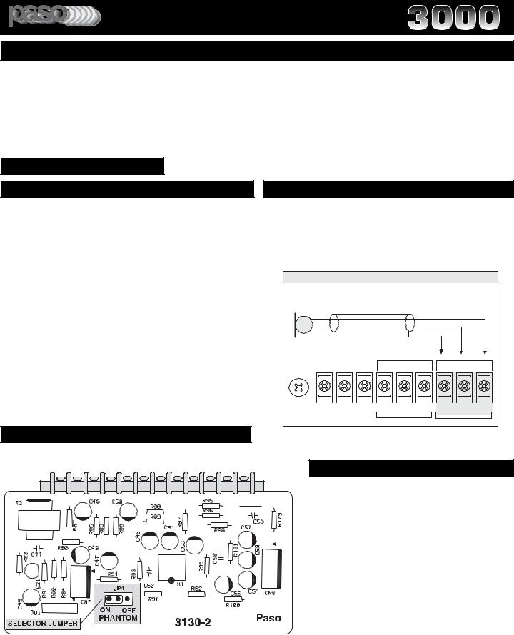
PHANTOM POWER SELECTOR
PHANTOM POWER SELECTOR JUMPER
By following the Preamplifier Printed Board layout as shown on Fig. 7A locate the Selector Jumper marked PHANTOM.
The Jumper Socket is marked as follows:
JP4 = ON - OFF - PHANTOM
To turn the Phantom Power On, re-position the Jumper to the ON POSITION (JP 4).
To change the Selector position lift the Mini Shorting Plug out of the socket pins and re-position as desired. Make sure the Mini Plug is lined up with the socket pins.
T3115/3130/3160BGM |
SPECIFICATIONS ARE SUBJECT TO CHANGE WITHOUT NOTICE |
PAGE 7 |
|


 ®
®
 PROFESSIONAL AUDIO & SOUND
INTEGRATED AMPLIFIERS
INSTALLATION AND WIRING
MUTING FUNCTIONS
VOX - VOICE ACTIVATED MUTING
VOX - VOICE ACTIVATED MUTING - The Amplifier is equipped with a noiseless, fast acting Logic Muting Function. When a signal is present at the MICROPHONE or TELEPHONE Input, either from a Microphone or a Telephone Paging source, the Muting Function is activated muting the source present at the AUX Input and as well as the source present at the PROGRAM input if selectively activated. Once the Signal (paging) is terminated the program is automatically restored on all muted inputs.
FOR THE VOX ATTACK AND DECAY TIMING REFER TO THE FIG. 9B DIAGRAM.
ACCESS TO MUTING SELECTORS
FOLLOW DIRECTIONS AS PER DIRECT MUTING FUNCTION.
VOX SENSITIVITY CONTROL
MUTING FUNCTIONS
The Amplifier provides several levels of Muting functions:
MICROPHONE |
Can be selectively Muted by internal selector |
|
TELEPHONE |
This input is never Muted |
|
AUXILIARY |
Can be selectively Muted by internal selector |
|
PROGRAM |
Can be selectively Muted by internal selector |
|
|
|
|
|
|
MUTING JUMPERS ADDRESS |
|
|
|
Several Jumpers are provided to set the Muting functions:
JUMPER NO. |
FUNCTION |
JP 1 |
MICROPHONE Mute ON - OFF |
JP 2 |
AUXILIARY Mute ON - OFF |
JP 3 |
PROGRAM Mute ON - OFF |
NOTE: The Microphone Input is provided with a unique MUTE and UNMUTE function. See the Mute/Unmute operation instructions in the appropriate section in this Manual.
The VOX Sensitivity Intervention threshold is adjusted at the factory for best performance and does not require re-touch- ing under normal circumstances. Should the Trimmer pre-setting require adjustment follow the instructions listed below.
VOX SENSITIVITY TRIMMER
3130 - 1
VOX |
|
OFF |
JP3 |
JP1 |
|
||
VR9 |
JP2 |
||
VOX |
|
ON |
ON OFF |
|
|
||
|
|
ON |
OFF |
SELECTOR JUMPERS
MIC |
AUX |
PROGRAM |
VOLUME |
VOLUME |
VOLUME |
Fig.8 - Main Amplifier PCB - VOX - MUTING Section - Top View
VOX SENSITIVITY ADJUSTMENT
CAUTION: PRIOR TO PERFORMING THIS OPERATION BE SURE TO FOLLOW THE
SAFETY NOTES REFERRING TO THE REMOVAL OF THE AMPLIFIER COVER.
AUTOMATIC PRECEDENCE THRESHOLD
The VOX Trimmer VR 9 sets the sensitivity level at which point the VOX is engaged during paging. The VOX Trimmer VR9 is located on the Main Printed Circuit Board (see Fig.89).
CAUTION: Procure a miniature screwdriver having a tip NO WIDER than 3/16” (3 mm). A larger tip screwdriver can damage the trimmer.
1)Turn all Input Controls to 0.
2)Turn Trimmer counterclockwise until it stops.
3)Connect a Paging Source (Microphone or Telephone) to the respective Input Terminals (For connection details refer to the appropriate section in this Manual).
4)While talking from the Paging Source (Microphone or Telephone) rotate the MIC (Front Panel) or TEL (Rear panel) Volume Control until the desired output level is achieved.
5)Connect a Music Source to the AUX 1 Input and rotate the AUX 1/CD Volume Control on the front panel until the desired output level is achieved.
6)While talking from the Paging Source (Microphone or Telephone) turn the Trimmer slowly clockwise until the Program (music) is cut-off (Muting activated).
VOX DEFEAT INSTRUCTIONS
In applications requiring the VOX to be inoperative rotate the VOX TRIMMER VR 9 fully counterclockwise. In this position the VOX is inoperative.
PAGE 8 |
Specifications are subject to change without notice |
T3115/3130/3160BGM |
 Loading...