


DMA2015
© copyright Paso Sound Products, Inc. 2005 Specifications are subject to change without notice
Innovation through technology since 1931
LISTED
COMMERCIAL
AUDIO
EQUIPMENT
30TJ
Installation Manual
and Operating Instructions
4 Channel - 2 Zone - VOX - Mute -
MOH - Phone Interface
TTOO RREEDDUUCCEE TTHHEE RRIISSKK OOFF FFIIRREE OORR EELLEECCTTRRIICC
SSHHOOCCKK DDOO NNOOTT EEXXPPOOSSEE TTHHIISS AAPPPPLLIIAANNCCEE TTOO
WWAATTEERR,, RRAAIINN OORR MMOOIISSTTUURRE
E
CAUTION !
REV. 1.5
IMPORTANT NOTE:
THIS OPERATING MANUAL IS PROVIDED AS AN INSTALLATION AND
AS AN OPERATING AID. PASO SOUND PRODUCTS, INC. DOES NOT ASSUME ANY
RESPONSIBILITY AS TO ITS ACCURACY AND SHALL NOT BE LIABLE IN TORT OR CON-
TRACT FOR ANY DIRECT CONSEQUENTIAL OR INCIDENTAL LOSS OR DAMAGE ARISING
FROM THE INSTALLATION, USE OR INABILITY TO USE THIS PRODUCT.
DDMMAA 22001155 -- 1155 WWaatttt RRMMSS
DDMMAA 22003300 -- 3300 WWaatttt RRMMSS
DDMMAA 22006600 -- 6600 WWaatttt RRMMSS
DDMMAA 22112200 -- 112200 WWaatttt RRMMSS
PROFESSIONAL AUDIO & SOUND
®
Series DMA
Integrated Amplifiers
Manual
OOMM 117700
DDiiggiittaall MMuussiicc AAmmpplliiffiieerrss

DESCRIPTION AND APPLICATIONS SPECIFICATIONS
PAGE 2
© copyright Paso Sound Products, Inc. 2005 Specifications are subject to change without notice
DMA2015/2030/2060/2120
UNPACKING
Immediately upon receipt of the amplifier, inspect the unit
and shipping container for indications of improper handling
or in transit damage. The equipment was carefully inspect-
ed and tested before leaving the factory. Notify the
Transportation Company immediately if any damage is
found. ONLY THE CONSIGNEE CAN FILE A CLAIM WITH
THE CARRIER FOR DAMAGE DURING SHIPMENT. Be
sure to save the carton and packing material as evidence of
damage for the shipper inspection. DO NOT SHIP the unit
back to the factory unless authorized by the factory.
IN TRANSIT DAMAGES ARE NOT COVERED BY THE
PASO WARRANTY.
❑❑
High Performance - High Reliability Design
❑❑
Wide Frequency Response - Very Low Distortion
❑❑
4 Channel Inputs - 2 Zone Outputs
❑❑
Up to 3 Balanced Microphone Inputs
❑❑
Phantom Power on all MIC Inputs
❑❑
MIC 2/AUX 1 and MIC 3/AUX 2 Inputs
With Stereo Summing
❑❑
AUX1 and AUX2 Inputs Attenuator
❑❑
600 ohm Transformer Balanced
Telephone Paging Input
❑❑
MIX Buss and 600 ohm Line Output
❑❑
Independent Input Controls
❑❑
AUX1 Remote Volume Controls
❑❑
External EQ Link
❑❑
Tone by-pass and EQ Link switches
❑❑
Addressable VOX Buss
Voice Activated Muting
❑❑
VOX Variable Time Delay Function
❑❑
Addressable MUTE Buss
❑❑
Direct Muting and Unmuting
❑❑
600 ohm and 8 ohm 2 Watt Max.
Music on Hold Amplifier
❑❑
MOH Amplifier Source Selector
❑❑
Zone 2, 2 Watt - 8 ohm Output
with Separate Control
❑❑
24 V DC 250 mA Regulated Power Supply Output
❑❑
8 ohm, 25 Volt & 70 Volt Output
❑❑
Optional 19” Rack Mounting with Kit
❑❑
Low profile - 2-Unit of Vertical Rack space
❑❑
UL 6500 Listed (US - CANADA)
PROFESSIONAL AUDIO & SOUND
®
DIGITAL MUSIC AMPLIFIERS
POWER OUTPUT: DMA2015 15 Watt RMS
DMA2030 30 Watt RMS
DMA2060 60 Watt RMS
DMA2120 120 Watt RMS
Distortion: 0.01% THD at 1 kHz rated power
Frequency Response: 20 hz - 30 Khz ± 2 dB
Inputs:
Input 1 MIC Electronically Balanced,
Transformer Balanced with MT250 (optional)
Input 2 Telephone Transformer Balanced
Input 3 MIC Electronically Balanced - AUX 1 (Stereo Sum.)
Input 4 MIC Electronically Balanced - AUX 2 (Stereo Sum.)
Sensitivity & Z:
Input 1
Mic 1
= 1.5 Mv - 250 ohm
Input 2
Te l
=100 Mv - 600 ohm - Transformer Balanced
Input 3
Mic 3
= 1.5 Mv - 250 ohm - AUX 1 = 100 Mv - 47K
ohm
Input 4
Mic 4
= 1.5 Mv - 250 ohm - AUX 2 = 100 Mv - 47K
ohm
Input Attenuator: AUX 1 and AUX 2
Phantom Power: All Microphone Inputs by internal jumper (18 V)
Hum & Noise:
Mic
-70 db,
Aux
-75 db 600 ohm Transformer bal-
anced
Telephone Paging Input:
EQ LINK: Preamp. out, Power Amp in with EQ Link Switch
Line Outputs: Line Out 600 ohm - 1.5 V loaded
Inputs/Outputs: MIX BUSS
Music on Hold Output: 600 ohm-1 Volt Transformer Balanced
Zone 2 Output: 2 Watt Max. - 8 ohm with Control
Main Output Impedance: 8 ohm, 25 Volt and 70 Volt line
Controls:
Front Panel: Input 1 Volume, Input 2 Volume, Input 3 Volume,
Input 4 Volume, Bass and Treble
Rear Panel: AUX 1 Attenuator - AUX 2 Attenuator, VOX Sensitivity
MOH/ZONE 1 Level Control - ZONE 2 Level Control
- VOX Sensitivity - MUTE Delay
Tone Controls: Bass and Treble ± 10 dB at 100 hZ and 10 KHz
Tone By-Pass: On - Off Switch Rear Panel
Remote Volume Control: INPUT 3 - AUX 1 Input Volume
MOH Source Selecti: AUX 1 and AUX 2
Zone 2 Source Select: AUX 1 and AUX 2
VOX BUSS: Available on all Inputs by internal Jumper
MUTE BUSS: Available on all Inputs by internal Jumper
MUTE DELAY: Adjustable from 3 Sec to 60 Sec (rear panel control)
Direct Muting: Exter nal Contact Closure
Unmuting: MUTES/UNMUTES MIC 1 only
Power Supply Output: 24 V DC - 250 mA Regulated
Rack Mounting: Optional 19” Rack Kit
Internal Cooling Fan: Thermally Controlled -
Models DMA2060, DMA2120
Protection: Power Surge, Overload and Thermal Protection
Power Requirement: 117 Volt, 50-60 hZ
Power Consumption: DMA2015 = AC = 570 VA - DMA2030 = 600 VA
DMA2060 = 670VA - DMA2120 = 850VA Max.
AC Accessory Outlet: 117 v - 500 W Max. Unswitched
Terminations: Screw Terminals, RCA Jacks
Housing Finish: Black
Output Power Indicator: Multi-color LED Signal and Clip
Dimensions: 10.75” W., 11” D., 4” H. with feet
(274X280X102 mm)
3.5” H
(89 mm)
. less feet
Net Weight: DMA2015 = 9.8 Lbs
(4.5 Kg)
- DMA2030 = 11.75 Lbs
(5.4 Kg)
DMA2060 = 12.5 Lbs
(5.7 Kg)
- DMA2120 = 14.25 Lbs
(6.5 Kg)
PAGE 3
SPECIFICATIONS ARE SUBJECT TO CHANGE WITHOUT NOTICEDMA2015/2030/2060/2120
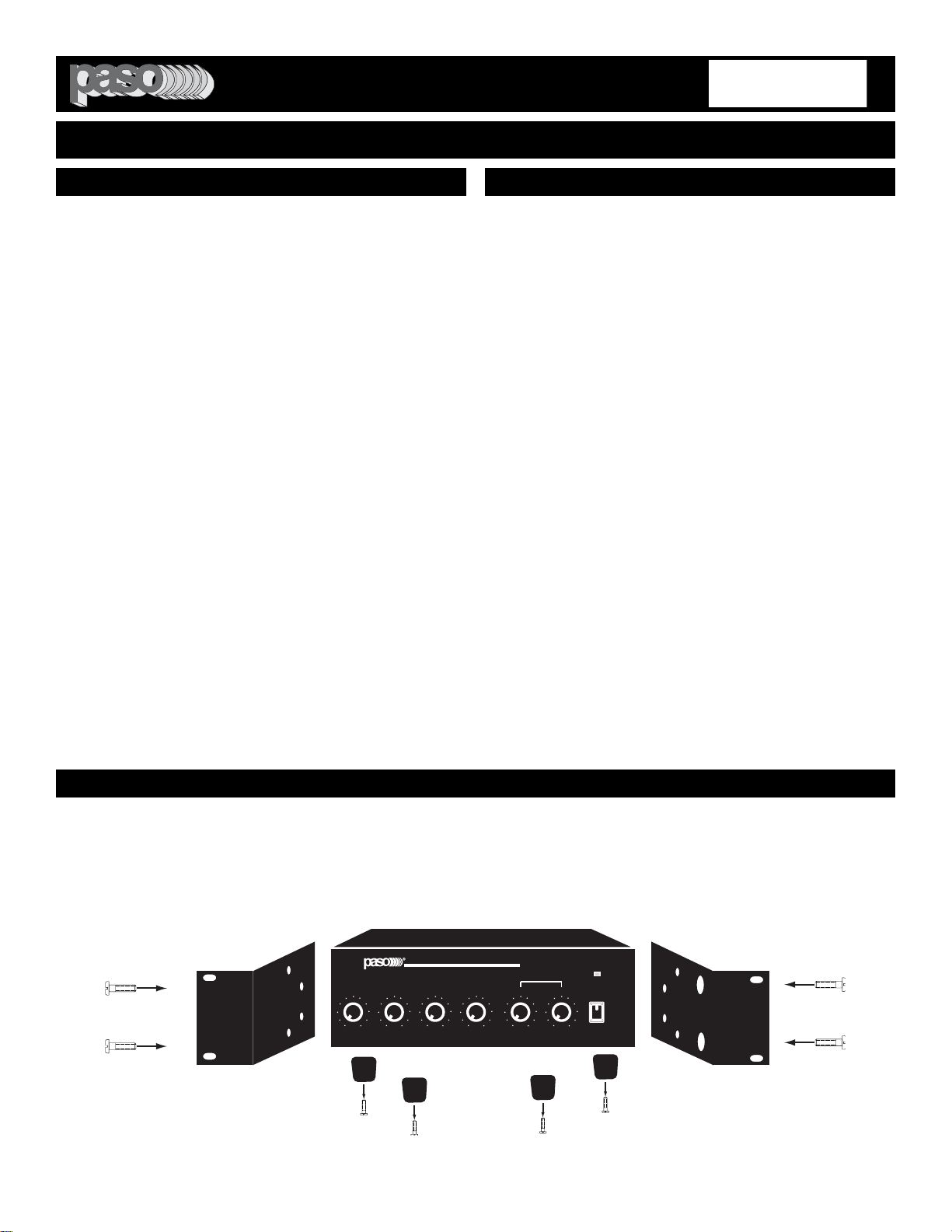
RACK MOUNTING
A) Procure the optional accessory Rack Mount Kit Model 27/3500.
B) Turn amplifier up side down and remove the four rubber feet by unscrewing the four holding screws.
C) Remove the bottom front screws on each side of the amplifier holding the amplifier cover.
D) Install the rack kit brackets by using the self-tapping screws provided.
POWER
O
INPUT 1/MIC
TEL
INPUT 3/AUX 1 INPUT 4/AUX 2
100 100 100 100
DIGITAL MUSIC AMPLIFIER
DIGITAL MUSIC SERIES
TM
DMA
BASS TREBLE
+10-10 +10-10
00
PROFESSIONAL AUDIO & SOUND
Fig. 3 - Rack Kit Mounting
READ BEFORE OPERATING READ BEFORE OPERATING
BEFORE OPERATING THE AMPLIFIER, BE SURE YOU
FULLY UNDERSTAND ALL INSTRUCTIONS AND FEA-
TURES OF THE UNIT.
1)
Read these instructions carefully.
2)
Keep these instructions.
3)
Heed all Warnings.
4)
Follow all instructions.
5) DO NOT use this apparatus near water.
6) Clean ONLY with a damp cloth.
7) DO NOT block any of the ventilation openings.
Install in accordance with the instructions provided.
8) DO NOT install near any heat sources such as
radiators, stoves, or other apparatus (including ampli-
fiers) that produce heat.
9) DO NOT mount amplifier into a container or a
closed unventilated closet while operating.
10) DO NOT place any object or accessory equipment
such as Tuners, Mixers, Cassette Decks, etc. on top of
the amplifier. Obstructing or closing the cabinet venti-
lation openings may cause overheating.
11) DO NOT defeat the safety purpose of the polar-
ized or grounding type plug. A polarized plug has two
blades with one wider than the other. A grounding type
plug has two blades and a third grounding prong. The
wide blade and or the third prong is provided for your
safety. When the provided plug does not fit into your
outlet, consult an electrician for replacement of the
obsolete outlet.
12) Use only the attachments and accessories speci-
fied in this manual.
13) If a cart is used, use caution when moving the
cart/apparatus combination to avoid injury from tip-
over.
14) Unplug this apparatus during lighting storms or
when unused for long periods of time.
15) Refer all servicing to qualified service personnel.
Servicing is required when the apparatus has been
damaged in any way, such as power supply cord or
plug is damaged, liquid has been spilled or objects
have fallen into the apparatus, the apparatus has been
exposed to rain or moisture, does not operate normal-
ly, or has been dropped.
16) DO NOT replace fuses unless power cord is
removed from the AC wall outlet.
17) DO NOT install accessories unless the power
cord is removed from the AC wall outlet.
TO REDUCE THE RISK OF FIRE OR
ELECTRIC SHOCK DO NOT EXPOSE
THIS APPLIANCE TO WATER, RAIN OR
MOISTURE
IMPORTANT SAFETY INSTRUCTIONS
PROFESSIONAL AUDIO & SOUND
®
DIGITAL MUSIC AMPLIFIERS
PAGE 4
SPECIFICATIONS ARE SUBJECT TO CHANGE WITHOUT NOTICE DMA2015/2030/2060/2120
POWER
O
INPUT 1/MIC
TEL
INPUT 3/AUX 1 INPUT 4/AUX 2
100 100 100 100
DIGITAL MUSIC AMPLIFIER
DIGITAL MUSIC SERIES
TM
DMA
BASS TREBLE
+10-10 +10-10
00
PROFESSIONAL AUDIO & SOUND
1
2 3 4
5 6 7
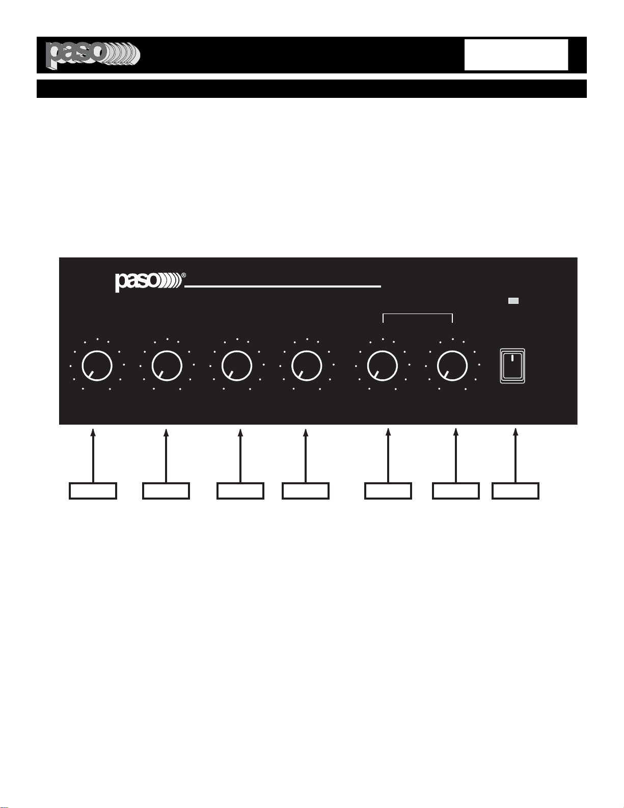
1) INPUT 1 Volume Control
2) TEL INPUT Volume Control
3) INPUT 3/AUX 1 Volume Control
4) INPUT 4/AUX 2 Volume Control
5) BASS Control
6) TREBLE Control
7) On-Off Power Switch
Fig. 4 - FRONT PANEL CONTROLS
PROFESSIONAL AUDIO & SOUND
®
DIGITAL MUSIC AMPLIFIERS
PAGE 5
SPECIFICATIONS ARE SUBJECT TO CHANGE WITHOUT NOTICEDMA2015/2030/2060/2120
AUX 1
47 Kohm 250 mV
INPUT 3 (MIC-AUX1)
15W RMS
AUX 2
47 Kohm 250 mV
INPUT 4 (MIC-AUX2)
INPUT 1 (MIC)
(AUX 2)
ATTENUATOR
(AUX 1)
ATTENUATOR
INPUT 4INPUT 3
VOX
SENS
MUTE
DELAY
3 - 60 SEC
8 OHM
2 Watt Max.
SP
INPUT 1 MAY BE
TRANSFORMER
BALANCED
WITH OPTIONAL
MODEL MT250
DMA2015
24 V DC
250 MA
-
+
1
2
3
4
5
8
7
9
12
11
10
6
13
14
DMA2015 Rear Panel
Manual
27
161718
20
21
22
24
25
26
15
19
23
28
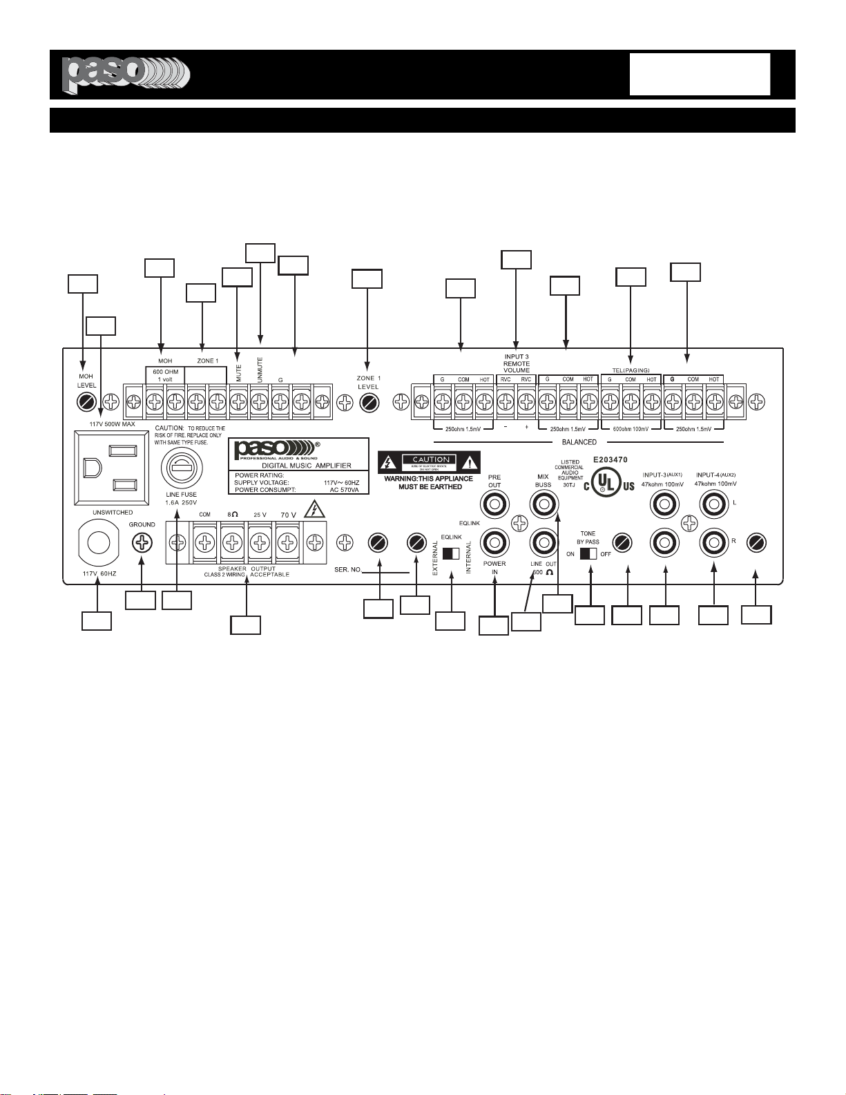
Fig. 5- REAR PANEL INPUTS - OUTPUTS - CONTROLS
1) MOH - Output Level Control
2) Unswitched AC Auxiliary Socket
3) 1 MOH - 600 ohm, 1 Volt Output
4) Zone 1 - 8 ohm, 2 Watt Max. Output
5) MUTE Terminal
6) MIC 1 UNMUTE Terminal
7) 24 Volt DC Regulated Power Supply Output
8) ZONE 1 - Output Level Control
9) INPUT 4 - AUX 2 Balanced Input
10) INPUT 3 Remote Volume Terminals
11) INPUT # _ AUX ! Balanced Input
12) TELEPHONE Paging Balanced Input 600 Ohm
13) INPUT 1 - MIC 1 Balanced Input
14) INPUT 4 - AUX 2 Input Attenuator
15) INPUT 4 - AUX 2 - Stereo Summing Jacks
16) INPUT 3 - AUX 1 - Stereo Summing Jacks
17) INPUT 3 - AUX 1 Input Attenuator
18) TONE BYPASS - ON/OFF SWITCH
19) MIX BUSS
20) LINE OUT 600 Ohm
21) EQ LINK - PREAMP. OUT/POWER AMP IN
22) Standard Module Port
23) MUTE Time Delay Control
24) VOX Sensitivity Control
25) Speaker Output Terminals
26) AC LIne Fuse
27) Chassis Ground
28) AC Power Cord
PROFESSIONAL AUDIO & SOUND
®
DIGITAL MUSIC AMPLIFIERS
PAGE 6
SPECIFICATIONS ARE SUBJECT TO CHANGE WITHOUT NOTICE
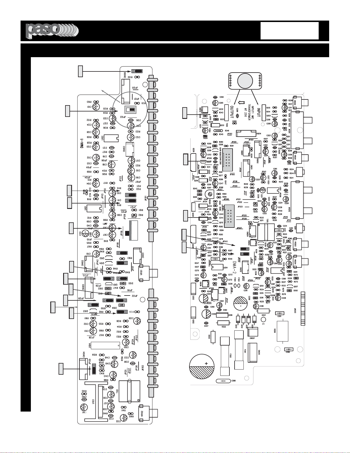
Fig. 6 - MAIN AND PREAMPLIFIER BOARD TOP VIEW
FUNCTION SWITCHES AND JUMPERS LOCATION
INPUT 1
TRANSFORMER
SWITCH
AMPLIFIER REAR PANEL
AUX 2 INPUT 4
INPUT 3
REMOTE
VOLUME
TEL PAGING
S114
OFF V1
INPUT 3
OFF MUTE1
S112
OFF M1
INPUT 3
MIC AUX1
SELECTOR
S109
MIC AUX1
S107
AUX1 AUX2
MOH - ZONE 1
AUX1 AUX2
SELECTOR
DMA COMPACT
PRE BOARD
S109
(INPUT 3)
MIC
AUX1
(INPUT 3)
S114
(INPUT 1)
OFF V1
OFF V1
S110
S115
UNMUTE
ON OFF
OFF M1
S113
(INPUT 1)
(INPUT 4) (INPUT 4)
OFF M1
OFF V1
S111
S108
S101
(INPUT 4)
AUX 2 MIC
AUX1
S107
(MOH)
AUX 2
PHANTOM
DIRECT
XFMER
(INPUT 1)
S102
(MIC 4)
S103
(MIC 3)
OFF ON
OFF ON
S104
(MIC 1)
OFF ON
PHANTOM
S112
(INPUT 3)
OFF M1
S110
OFF V1
INPUT3
OFF VOX1
S115
ON OFF
MIC 1
UNMUTE
PHANTOM
POWER
MIC 4
S102
ON OFF
PHANTOM
POWER
MIC 3
S103
ON OFF
INPUT1
XFMER
DIRECT SWITCH
S105
XFMER DIRECT
INPUT1
OFF VOX1
INPUT 1
OFF MUTE1
S113
OFF M1
S204
OFF M1
TEL
OFF MUTE1
S203
OFF V1
TEL
OFF VOX1
INPUT 4
MIC AUX2
SWITCH
S101
MIC AUX2
PHANTOM
POWER
MIC 1
S104
ON OFF
S105
AUX 1 INPUT 3 INPUT 1 MIC
MOH 600 OHM ZONE 1 8 OHM MUTE UNMUTE 24 VDC 250 MA
INPUT
OUTPUT
MIC INPUT
TRANSFORMER
MT 250
DMA COMPACT
MAIN BOARD
TEL
OFF M1
OFF V1
S204
TEL
S203
CN210
EQ MODULE
CN209
CHIME MODULE
AMPLIFIER REAR PANEL
OPTIONAL
EQ CARD
SOCKET
CN 210
OPTIONAL
CHIME CARD
SOCKET
CN 209
OPTIONAL
MIC TRANSFORMER
SOCKET
T 202
TOP PRINTED CIRCUIT BOARD
BOTTOM PRINTED CIRCUIT BOARD
PROFESSIONAL AUDIO & SOUND
®
DIGITAL MUSIC AMPLIFIERS
DMA2015/2030/2060/2120

PAGE 7
SPECIFICATIONS ARE SUBJECT TO CHANGE WITHOUT NOTICE
DMA2015/2030/2060/2120
FUNCTION SWITCHES AND JUMPERS DEFAULT SETTING TABLE
S102 INPUT 4 (MIC 4) PHANTOM POWER ON - OFF OFF
S103 INPUT 3 (MIC 3) PHANTOM POWER ON - OFF OFF
S104 INPUT 1 (MIC 1) PHANTOM POWER ON - OFF OFF
S108 INPUT 4 VOX 1 - OFF OFF
S110 INPUT 3 VOX 1 - OFF OFF
S114 INPUT 1 (MIC 1) VOX 1 - OFF V1
S115 INPUT 1 (MIC 1) UNMUTE ON - OFF OFF
S111 INPUT 4 (AUX 2/MIC) MUTE 1 - OFF M1
S112 INPUT 3 (AUX 1/MIC) MUTE 1 - OFF M1
S113 INPUT 1 (MIC 1) MUTE 1 - OFF OFF
MAIN PCB JUMPERS (Lower Board)
S203 TEL INPUT VOX 1 - OFF V1
S204 TEL INPUT MUTE 1 - OFF OFF
JUMPER AND JUMPER FUNCTION FACTORY FACTORY
SWITCH ID NO. REFERENCE DESCRIPTION SETTING SETTING
PREAMPLIFIER PCB JUMPERS (Upper Board)
S101 INPUT 4 MIC 4 OR AUX 2 SWITCH AUX 2
S105 INPUT 1 XFMER/DIRECT SWITCH DIRECT
S109 INPUT 3 - MIC 3 OR AUX 1 JUMPER AUX 1
SWITCHES/JUMPERS
S107 MOH/ZONE 1 INPUT SOURCE AUX 1 - AUX 2 AUX 1
MOH/ZONE 1 BOARD JUMPERS
S201 EQ LINK Inserts External EQ between INTERNAL
Preamp Out and Power Amp Input
S202 TONE BYPASS Defeats Front Panel Bass & Treble Controls SWITCH OFF
REAR PANEL SWITCHES
THE FOLLOWING INSTRUCTIONS REQUIRE THE REMOVAL OF THE AMPLIFIER PROTECTIVE COVER AND ARE
PROVIDED FOR USE BY QUALIFIED PERSONNEL ONLY.
TO AVOID THE RISK OF ELECTRICAL SHOCK DO NOT PERFORM ANY INSTALLATION OR SERVICING UNLESS YOU
ARE QUALIFIED TO DO SO. REFER INSTALLATION OR SERVICING TO QUALIFIED PERSONNEL.
CAUTION !
REMOVAL OF THE AMPLIFIER COVER PRESENTS AN ELECTRICAL SHOCK HAZARD
ALWAYS REMOVE THE POWER CORD FROM THE AC WALL OUTLET
PROFESSIONAL AUDIO & SOUND
®
DIGITAL MUSIC AMPLIFIERS

PAGE 8
SPECIFICATIONS ARE SUBJECT TO CHANGE WITHOUT NOTICE
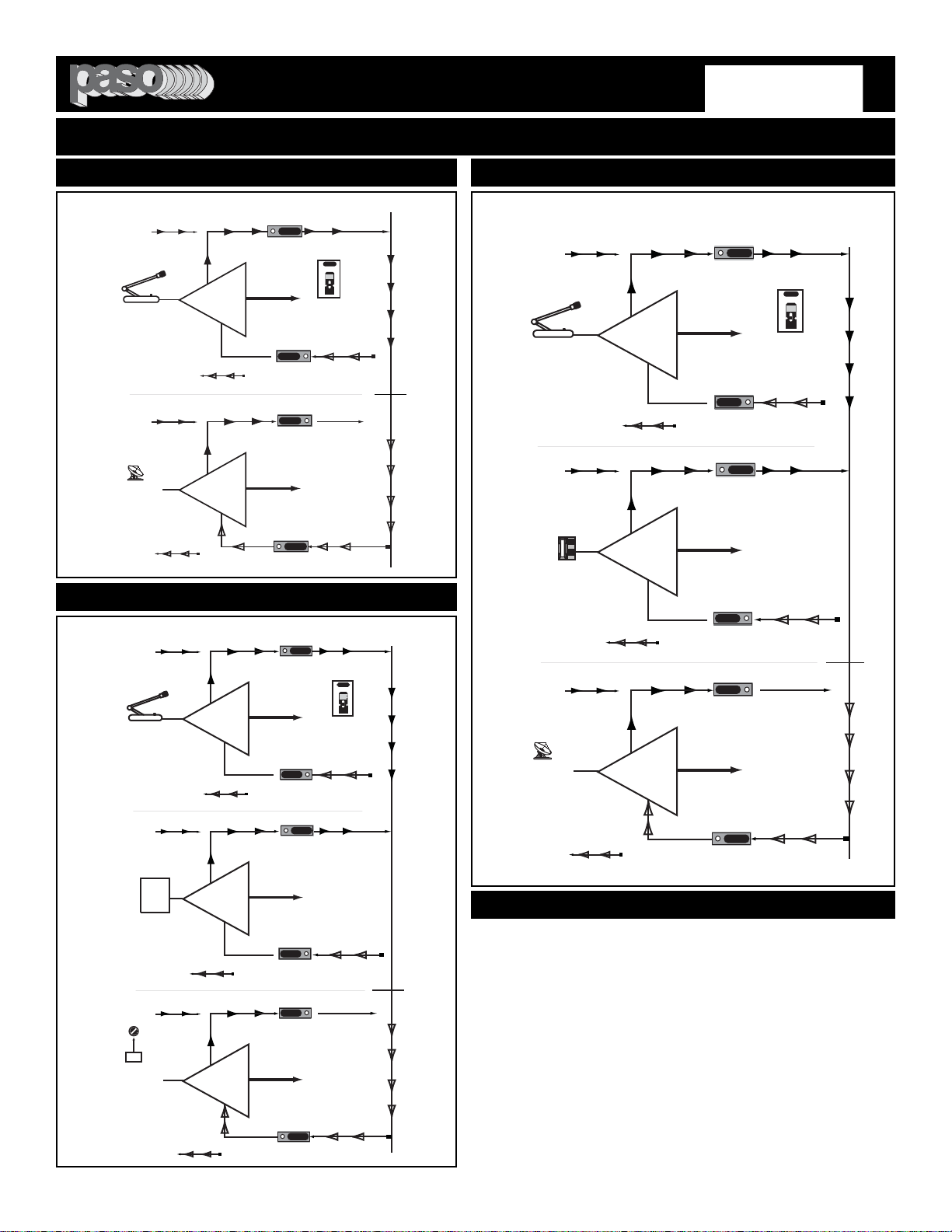
FUNCTION SWITCHES AND JUMPERS
UNDERSTANDING THE INPUT FUNCTIONS
V1
M1
ANY
INPUT
AUDIO OUT
SOURCE IN
DMA Anyinput
VOX SEND
MUTE RECEIVE
TO VOX BUSS
FROM MUTE BUSS
VOX AND MUTE - The Amplifier provides an independent VOX
and MUTE SYSTEM
FUNCTION SOCKETS - EACH INPUT IS PROVIDED WITH A
VOX (V1) AND A MUTE (M1) SOCKET.
INPUTS VOX AND MUTE FUNCTION - All Inputs provide a VOX
SEND and a MUTE RECEIVE functions. The VOX and MUTE
functions are SWITCHED-ON, on each Input, by Internal Jumpers
provided for each Input.The VOX BUSS SEND (V1) and the MUTE
BUSS RECEIVE (M1) can be independently SWITCHED-ON or
OFF to suit the application requirement.
Fig. 8 - Any Input VOX and MUTE Functions
JUMPER SETTINGS - The VOX and MUTE Functions are
SWITCHED-ON or OFF by setting the JUMPERS on the VOX (A)
and MUTE (B) SOCKET. See Fig. 8A.
The SOCKETS are located on the Main PCB inside the Amplifier
as shown on the SWITCHES and JUMPERS LOCATION DIA-
GRAM in this Manual. Each Socket is identified by an ID NUMBER
and the FUNCTION and DEFAULT settings are listed on the
FUNCTION SWITCHES and JUMPERS DEFAULT SETTING
TABLE in this Manual.
TO SET: Lift the Jumper and reset as required. making sure that
the JUMPER is properly positioned over the two shorting pins.
The VOX JUMPER has two positions: OFF, and V1
The MUTE JUMPER has two positions: OFF, and M1
V1
M1
X
MUTE 1 BUSS OFF
AUDIO OUT
DMA Anyinput 02
VOX SEND
MUTE RECEIVE
S114
JUMPER
ANY
INPUT
SOURCE IN
VOX 2 BUSS ON
OFF M1
OFF V1
S113
Fig. 8B - Any Input VOX 1 activated and MUTE 1 OFF
JUMPER
A
B
VOX JUMPERS
SOCKET
MUTE JUMPERS
SOCKET
SOCKET
ID NO.
S114
OFF M1
OFF V1
S113
The figure below shows how the VOX 1 Logic Switch is switched
ON and the MUTE 1 Logic Switch is SWITCHED-OFF by moving
the Jumpers as indicated. When the Input is activated by a Source
signal the corresponding VOX Signal is sent to the V1 BUSS.
When the VOX 1 is activated by any Input the MUTE Signal is
present on the MUTE 1 BUSS and it will MUTE any Input with the
MUTE M1 turned on.
SETTING THE VOX AND MUTE JUMPERS
Fig. 8A - VOX and MUTE Sockets
IMPORTANT NOTE
BE SURE NOT TO SET BOTH THE VOX AND
CORRESPONDING MUTE ON THE SAME
INPUT OR THE INPUT WILL MUTE ITSELF
WHEN ACTIVATED.
EXAMPLE: INPUT 1 - V 1 and M 1 BOTH ON.
PROFESSIONAL AUDIO & SOUND
®
DIGITAL MUSIC AMPLIFIERS
DMA2015/2030/2060/2120
PAGE 9
SPECIFICATIONS ARE SUBJECT TO CHANGE WITHOUT NOTICE
FUNCTION SETTINGS EXAMPLES
V1
M1
INPUT 1
X
MUTE 1 BUSS OFF
MIC OUT
MIC IN
VOX SEND
MUTE RECEIVE
V1
OFF
M1
INPUT 3
AUX 1
MUTE 1 BUSS ON
MUSIC OUT
MUSIC
IN
DMA Input 1-3- V1 - 01
VOX SEND
MUTE RECEIVE
VOX 1 BUSS OFF
X
VOX 1 BUSS ON
VOX 1 BUSS
MUTE 1 BUSS
WHEN MIC 1 IS
ACTIVATED THE VOX 1
BUSS IS SWITCHED-ON
AND THE SIGNAL
PRESENT ON THE
MUTE 1 BUSS WILL
MUTE INPUT 3/AUX 1
WHEN MIC 1 IS ACTIVATED
THE VOX 1 BUSS IS
SWITCHED-ON AND THE
SIGNAL PRESENT ON THE
MUTE 1 BUSS WILL MUTE THE
MUSIC FROM INPUT 3/AUX 1
JUMPER
VOX - MUTE JUMPERS SETTING
S114
S113
OFF M1
OFF V1
OFF M1
OFF V1
S110
S112
VOX 1 BUSS
MUTE 1 BUSS
V1
OFF
M1
OFF
INPUT 3
AUX 1
MUTE 1 BUSS ON
MUSIC OUT
MUSIC
IN
DMA Input 1-3 -Tel - 01
VOX SEND
MUTE RECEIVE
VOX 1 BUSS OFF
X
WHEN MIC1 OR TEL ARE
ACTIVATED THE VOX 1
BUSS IS SWITCHED-ON
AND THE SIGNAL PRESENT
ON THE MUTE 1 BUSS WILL
MUTE THE MUSIC FROM
INPUT 3/AUX 1
V1
M1
INPUT 1
X
MUTE 1 BUSS OFF
MIC OUT
MIC IN
VOX SEND
MUTE RECEIVE
VOX 1 BUSS ON
WHEN MIC1 IS
ACTIVATED THE VOX 1
BUSS SWITCHED-ON
AND THE SIGNAL
PRESENT ON THE
MUTE 1 BUSS WILL
MUTE THE INPUT
3/AUX 1
V1
OFF
M1
OFF
TEL INPUT
X
MUTE 1 BUSS OFF
PHONE OUT
TEL IN
VOX SEND
MUTE RECEIVE
VOX 1 BUSS ON
WHEN THE TEL
INPUT IS ACTIVATED
THE VOX 1 BUSS IS
SWITCHED-ON AND
THE SIGNAL
PRESENT ON THE
MUTE 1 BUSS WILL
MUTE INPUT 3/AUX 1
VOX - MUTE JUMPERS SETTING
JUMPER
S114
OFF V1
OFF M1
OFF V1
S203
S112
OFF M1
OFF V1
OFF M1
S113
S204
S110
EXAMPLE 9
JUKEBOX
IN
WHEN INPUT 3/AUX 1 IS
ACTIVATED THE VOX BUSS
IS SWITCHED-ON AND THE
SIGNAL PRESENT ON THE
MUTE BUSS WILL MUTE
THE MUSIC FROM INPUT
4/AUX 2
23
MUTE-
DELAY
3 to 60 Sec
VOX 1 BUSS
MUTE 1 BUSS
V1
OFF
M1
OFF
INPUT 3
AUX 1
MUTE 1 BUSS ON
MUSIC OUT
MUSIC
IN
DMA Input 1- 3 - 4 - 03
VOX SEND
MUTE RECEIVE
VOX 1 BUSS OFF
X
WHEN MIC1 OR THE
JUKEBOX ARE ACTIVATED
THE VOX 1 BUSS IS
SWITCHED-ON AND THE
SIGNAL PRESENT ON THE
MUTE 1 BUSS WILL MUTE
THE MUSIC FROM INPUT
V1
M1
INPUT 1
X
MUTE 1 BUSS OFF
MIC OUT
VOX SEND
MUTE RECEIVE
VOX 1 BUSS ON
WHEN MIC1 IS
ACTIVATED THE VOX 1
BUSS SWITCHED-ON
AND THE SIGNAL
PRESENT ON THE
MUTE 1 BUSS WILL
MUTE THE INPUT
4/AUX 2
V1
OFF
M1
OFF
X
MUTE 1 BUSS OFF
JUKEBOX OUT
VOX SEND
MUTE RECEIVE
VOX 1 BUSS ON
VOX - MUTE JUMPERS SETTING
JUMPER
S114
OFF V1
OFF M1
OFF V1
S110
S111
OFF M1
OFF V1
OFF M1
S113
S112
S108
INPUT 4
AUX 2
MIC IN
EXAMPLE 9B
EXAMPLE 9A
EXAMPLES
EXAMPLE 9 - INPUT 1 (MIC 1) mutes INPUT 3/AUX 1. When the
Microphone is activated the Music on AUX 1 is muted.
EXAMPLE 9A - INPUT 1 (MIC 1) and TEL IN (Phone Paging) both
mute INPUT 3/AUX 1. When the Microphone or the Phone Paging
are activated the Music on AUX 1 is muted.
EXAMPLE 9B - INPUT 1 (MIC 1) mutes INPUT 3/AUX 1. INPUT 3
(Jukebox) mutes INPUT 4 (Satellite Receiver). When the Jukebox is
turned-On the Background Music on AUX 2 is muted. The
Microphone Paging when activated will mute the Background Music
but not the Jukebox. The MUTE 2 DELAY (Reference 23) Control is
provided to adjust the duration of the MUTE when the Jukebox is
activated (this effects also the duration of the MUTE when Paging
from the Microphone.
PROFESSIONAL AUDIO & SOUND
®
DIGITAL MUSIC AMPLIFIERS
DMA2015/2030/2060/2120
PAGE 10
SPECIFICATIONS ARE SUBJECT TO CHANGE WITHOUT NOTICE
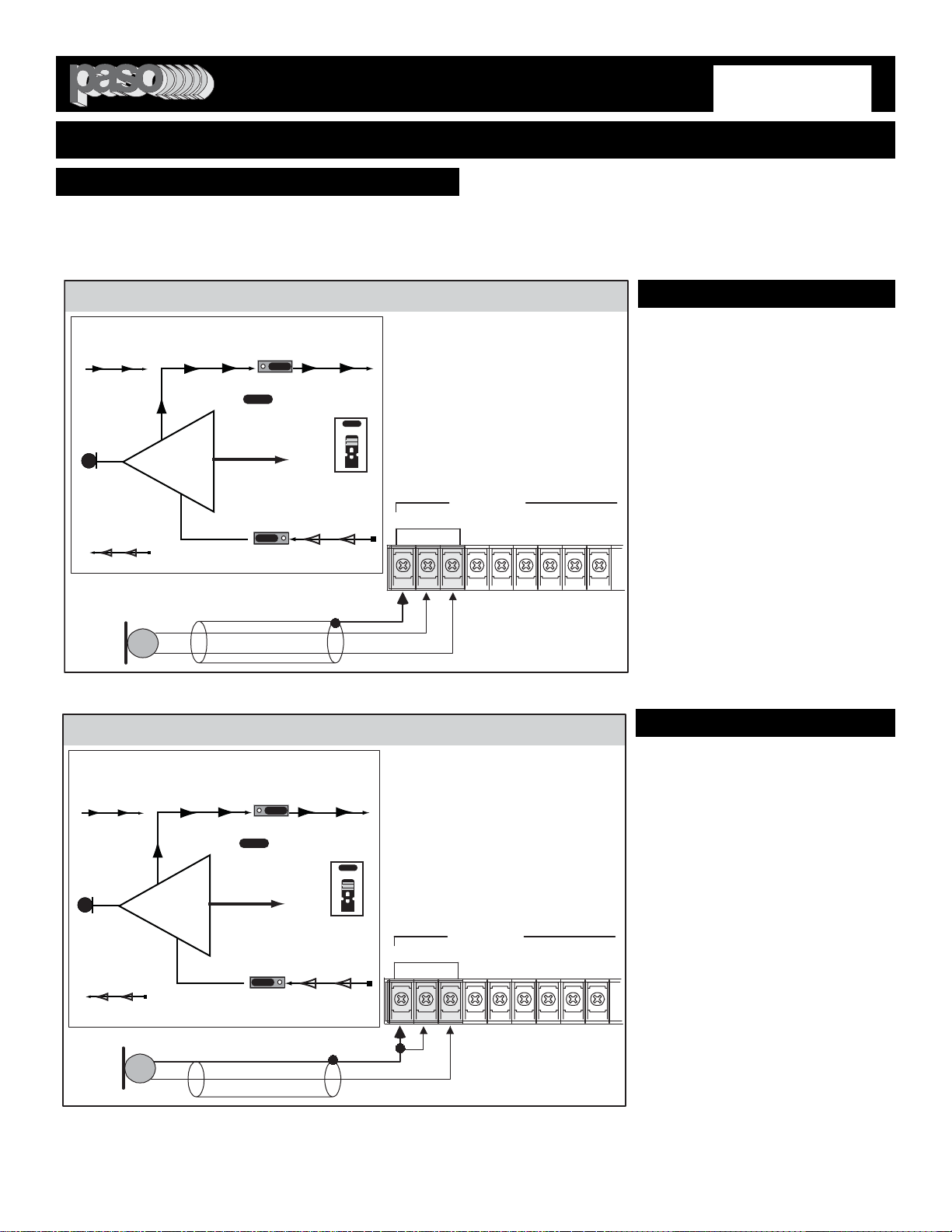
INPUT 1 - MICROPHONE INPUT
MICROPHONE TYPE
The Microphone Input accepts Low Impedance (250-600 ohm)
Dynamic Microphones. The Microphone may be a balanced output
type (three wire) or an unbalanced output type (two wire).
PASO MICROPHONES
All PASO low impedance Microphones have a balanced output for
best performance. Connect the RED lead to terminal HOT, the
WHITE lead to terminal COM and the SHIELD to terminal G.
DMA Micbal 01
THREE LEADS BALANCED MICROPHONE WIRING
SHIELD
MIC
Lo Z
RED
WHITE
INPUT 1 - Default Jumper Settings
INPUT 1 (MIC)
G COM HOT
BALANCED
250ohm 1.5mV
The Diagram at Left shows the
Default Settings for INPUT 1.
VOX 1 is SWITCHED ON
MUTE 1 is SWITCHED OFF
When the INPUT 1 (MIC 1) is
activated the VOX 1 BUSS is ON
and it will MUTE any Input with the
MUTE 1 Setting SWITCHED ON.
NOTE: To change the
INPUT Default Settings
refer to the appropriate
section in this Manual
The microphone leads color refers to Paso Microphones only.
When using other brand refer to instructions packed with that
unit.
V1
VOX 1 BUSS
ACTIVATED
INPUT 1
X
MUTE 1 BUSS OFF
AUDIO OUT
MIC IN
Input 1 - V1 - 01
VOX SEND
MUTE RECEIVE
VOX - MUTE JUMPERS SETTING
=
JUMPER
JUMPER
S114
JUMPER
OFF M1
OFF V1
S113
TWO LEADS UNBALANCED MICROPHONE WIRING
INPUT 1 - Default Jumper Settings
INPUT 1 (MIC)
G COM HOT
BALANCED
250ohm 1.5mV
The Diagram at Left shows the
Default Settings for INPUT 1.
VOX 1 is SWITCHED ON
MUTE 1 is SWITCHED OFF
When the INPUT 1 (MIC 1) is
activated the VOX 1 BUSS is ON
and it will MUTE any Input with the
MUTE 1 Setting SWITCHED ON.
NOTE: To change the
INPUT Default Settings
refer to the appropriate
section in this Manual
SHIELD
MIC
Lo Z
HOT LEAD
DMA Micunbal 01
V1
VOX 1 BUSS
ACTIVATED
INPUT 1
X
MUTE 1 BUSS OFF
AUDIO OUT
MIC IN
Input 1 - V1 - 01
VOX SEND
MUTE RECEIVE
VOX - MUTE JUMPERS SETTING
=
JUMPER
JUMPER
S114
JUMPER
OFF M1
OFF V1
S113
WIRING
CABLE
MICROPHONE INPUT
Attach the microphone leads to the ter-
minal strip as per diagrams at left.
DO NOT GROUND THE MICROPHONE
CABLE SHIELD TO THE CHASSIS OF
THE AMPLIFIER
BALANCED MICROPHONE
IMPORTANT NOTE: The use of an
unbalanced Microphone (two leads) is
not recommended. For best results in a
PA Application always use a
Unidirectional Dynamic, Low
Impedance, Balanced Microphone
(three leads).
UNBALANCED MICROPHONE
Attach the Microphone leads to the ter-
minal strip as per diagram in Fig 10A.
The cable length should not exceed: 15
Ft. (4.5 m).
Fig. 10 - Balanced Microphone Input 1 Wiring
CAUTION:
TO PREVENT POSSIBLE DAMAGE TO SPEAKERS OR THE AMPLIFIER
ALL INPUT CONNECTIONS MUST BE MADE WITH THE AMPLIFIER POWER OFF.
CABLE LENGTH - If the distance
between the Microphone and the
Amplifier Input is greater than 15 ft (4.5
m) a Balanced Microphone must be
used. Use a two conductor shielded wire
and connect Microphone to Amplifier as
per Diagram in Fig. 10.
MICROPHONE CABLE ROUTING - The
Microphone Cable should be carefully
routed. Improper Cable routing will
cause spurious oscillations, regenerative
noises, hum, etc. that may permanently
damage the Amplifier.
z Do not route cable next to power
lines.
z
Do not route cable near or over
Fluorescent Fixtures.
z
Do not route cable next to
Speaker Wires.
z
Do not install cable inside Power
Line Conduits.
z
Avoid the use of staples that may
penetrate the cable.
Fig. 10A - Unbalanced Microphone Input 1 Wiring
INSTALLATION AND WIRING
PROFESSIONAL AUDIO & SOUND
®
DIGITAL MUSIC AMPLIFIERS
DMA2015/2030/2060/2120
 Loading...