


PPowerMaster ™ Pro
MODEL F-350P
Framing Nailer
P
IMPORTANT!
DO NOT DESTROY
It is the customers responsibility to have all operators and service personnel read and understand this manual.
OPERATING MANUAL AND SCHEMATIC
PRINTED IN U.S.A. |
|
© 2016, Illinois Tool Works Inc. |
1 |
515022-5 |
11/16
INTRODUCTION
The PASLODE® F-350P framing nailer is a quality-built tool designed for use in residential framing applications. This tool will deliver efficient, dependable performance when used according to the manufactures guidelines. Please study this manual including the safety instructions to fully understand the operation of this tool.
TOOL AND FASTENER SPECIFICATIONS ................................................................. |
3 |
SAFETY INSTRUCTIONS ........................................................................................... |
4 |
TOOL INSTALLATION AND OPERATION ................................................................ |
5-6 |
AIR SYSTEMS ............................................................................................................. |
7-8 |
FEATURES AND BENEFITS .......................................................................................... |
9 |
EXPLODED VIEW AND SPARE PARTS LIST ....................................................... |
10-11 |
MAINTENANCE ....................................................................................................... |
12-13 |
TROUBLESHOOTING .................................................................................................. |
14 |
WARRANTY .................................................................................................................. |
15 |
ACCESSORIES ........................................................................................................... |
16 |
2
TOOL AND FASTENER SPECIFICATIONS
TOOL SPECIFICATIONS
MODEL NO. |
F-350P (Part# 515000) |
|
|
HEIGHT |
13.5” |
WIDTH |
5.5" |
LENGTH |
20.5" |
WEIGHT |
7 lbs. 13 oz. |
|
|
OPERATING PRESSURE |
80 to 120 p.s.i. (5.5 to 8.3 bars) |
|
|
FASTENER SPECIFICATIONS
NAIL LENGTH |
2" - 3¼" |
|
|
SHANK DIAMETER |
.113 - .131 |
|
|
TOOL AIR FITTINGS:
This tool uses a 3/8” N.P.T. male plug. The fitting must be capable of discharging tool air pressure when disconnected from the air supply.
OPERATING AIR PRESSURE:
80 to120 p.s.i. (5.5 to 8.3 bars). Select the operating air pressure within this range for best tool performance.
DO NOT EXCEED THIS RECOMMENDED OPERATING PRESSURE.
3

SAFETY INSTRUCTIONS
SAFETY FIRST
These safety instructions provide information necessary for safe operation of Paslode® tools. DO NOT ATTEMPT
TO OPERATE THE TOOL UNTIL YOU READ AND
UNDERSTAND ALL SAFETY PRECAUTIONS AND
MANUAL INSTRUCTIONS.
WEAR EYE AND HEARING PROTECTION
Always wear hearing and eye protection devices, that conform to ANSI Z87.1 requirements, when operating or working in the vicinity of a tool. As an employer you are responsible for enforcing the use of eye protection.
Wear hard hats in environments that require their use.
THE TOOL MUST BE USED ONLY FOR THE PURPOSE FOR WHICH IT WAS DESIGNED
Do not throw the tool on the floor, strike the housing in any way or use the tool as a hammer to knock material into place.
NEVER ENGAGE IN HORSEPLAY WITH THE TOOL
The tool is not a toy so do not use it like one. Never engage in horseplay with the tool or point it at yourself or any other person, even if you think it is not loaded.
NEVER ASSUME THE TOOL IS EMPTY
Check the magazine for fasteners that may be left in the tool. Even if you think the tool is empty or disconnected, never point it at anyone or yourself. Unseen fasteners could fire from the tool.
NEVER CLAMP THE TRIGGER IN A LOCKED OR OPERATING POSITION
The trigger of the tool must never be tampered with, disabled or clamped in a locked or operating position since this will cause the tool to drive a fastener any time the work contacting element depressed.
DO NOT LOAD FASTENERS WITH THE AIR LINE CONNECTED, OR WITH THE TOOL TRIGGER OR WORK CONTACTING ELEMENT DEPRESSED
When loading fasteners into the tool be sure you disconnect the air line and that you do not depress the trigger or work contacting element.
OPERATE THE TOOL ONLY ON A WORKPIECE
The tool should be operated only when it is in contact with the workpiece. Even then you should be careful when fastening thin material or working near the edges and corners of the workpiece since the fasteners may drive through or away from the workpiece.
DO NOT DISABLE OR REMOVE THE WORK CONTACTING ELEMENT
This tool is equipped with a safety mechanism, called a work contacting element, to help prevent accidental firing. Never tamper with, disable or remove the work contacting element. Do not use the tool unless the work contacting element is working properly. The tool could
fire unexpectedly.
DISCONNECT THE TOOL WHEN NOT IN USE
Always disconnect the tool from the air line when it is not in use, when you leave the work area or when moving the tool to a new location. The tool must never be left unattended because people who are not familiar with the tool might handle it and injure themselves or others.
CARRY THE TOOL ONLY BY THE HANDLE
Always carry the tool by the handle only. Never carry the tool by the air hose or with the trigger depressed since you could drive a fastener unintentionally and injure yourself or someone else.
DO NOT WEAKEN THE TOOL HOUSING
The tool housing is a pressure vessel and should never be weakened by having your companyʼs name, area of work or anything else stamped or engraved into its surface.
DISCONNECT THE TOOL WHEN PERFORMING REPAIRS AND CLEARING JAMS
Never attempt to clear a jam or repair a tool unless you have disconnected the tool from the air line and removed all remaining fasteners from the tool.
ALWAYS USE THE PROPER FITTING FOR THE TOOL
Only MALE pneumatic type air connectors should be fitted to the tool, so that high pressure air in the tool is vented to atmosphere as soon as the air line is disconnected.
NEVER install FEMALE quick disconnect couplings on the tool. Female couplings will trap high pressure air in the tool when the air line is disconnected, leaving the tool charged and able to drive at least one fastener.
DO NOT EXCEEDTHE MAXIMUM RECOMMENDED AIR PRESSURE
Operate the tool only at the recommended air pressure. Do not exceed the maximum air pressure marked on the tool. Be sure the air pressure gauge is operating properly and check it at least twice a day.
Never use any bottled air or gases such as oxygen to operate the tool since they could cause the tool to
explode. Do not operate in explosive atmospheres.
INSPECT TOOL FOR PROPER OPERATION
Clean the tool at least daily and lubricate as required.
Never operate a dirty or malfunctioning tool.
USE ONLY PASLODE RECOMMENDED PARTS AND FASTENERS
Use only parts and fasteners specifically designed and recommended by Paslode for use in the tool and for work to be done. Using unauthorized parts and fasteners or modifying the tool in any way creates dagerous situations. Replace all missing warning labels. Refer to tool schematic for correct placement and part number.
WARNING
Failure to follow any of the above instructions could result in severe personal injury to tool user and bystanders or cause damage to tool and property.
Contact your local Paslode Representative for presentation of Paslodeʼs Safety Awareness Program
4
TOOL INSTALLATION
Your Paslode tool comes ready for immediate use and can be installed by following these steps:
1.SAFETY - All tool operators and their immediate supervisors must become familiar with the operator safety instructions before operating the tool. The instructions are on page 4 of this manual.
2.Included with each tool are one copy of this Safety and Maintenance manual and one copy of the Tool Schematic. Keep these publications for future reference. An ownership registration card is
also included. This card must be completed and
returned to Paslode immediately to register your ownership.
3.The plastic cap in the air inlet of the tool must be removed before the male fitting is installed. The fitting must be a male pneumatic type that discharges the air from the tool when the air line is disconnected.
4.Install a filter/regulator/lubricator unit, with a gauge as close as practical to the tool, preferably within ten feet. Refer to the Air Systems section of this manual for air hose requirements and lengths. In general, no other special installation is required.
5.If the operator is working at a bench or table, it is usually best to run the air line underneath the bench. A small tray under the benchtop can hold the fastener supply and the tool when not in use.
6.If this tool does not work when it is first connected, do not try to make repairs. Call your Paslode
representative immediately.
TOOL OPERATION
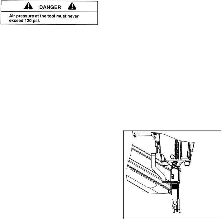
Depth of Drive Adjustment
(On tools equipped with this feature)
The depth of drive adjustment is made by turning the thumbwheel on the work contact element.
If the tool is overdriving (the fastener head is driven below the work surface), the work contact element should be moved downward. If the fasteners stand up (the head not flush with the surface), the work contact element should be moved up.
Adjust the work contact element until the fastener head depth meets job requirements.
ROTATE
 THUMBWHEEL
IN EITHER
DIRECTION
WORK 
CONTACT
ELEMENT
5
TOOL OPERATION - continued
Loading of Nails
Step 1 - Grasp the handle firmly.
Step 2 - Insert one or two strips of nails into the rear of the magazine.
Step 3 - Pull the follower to the rear of the magazine until it is engaged behind the nails.
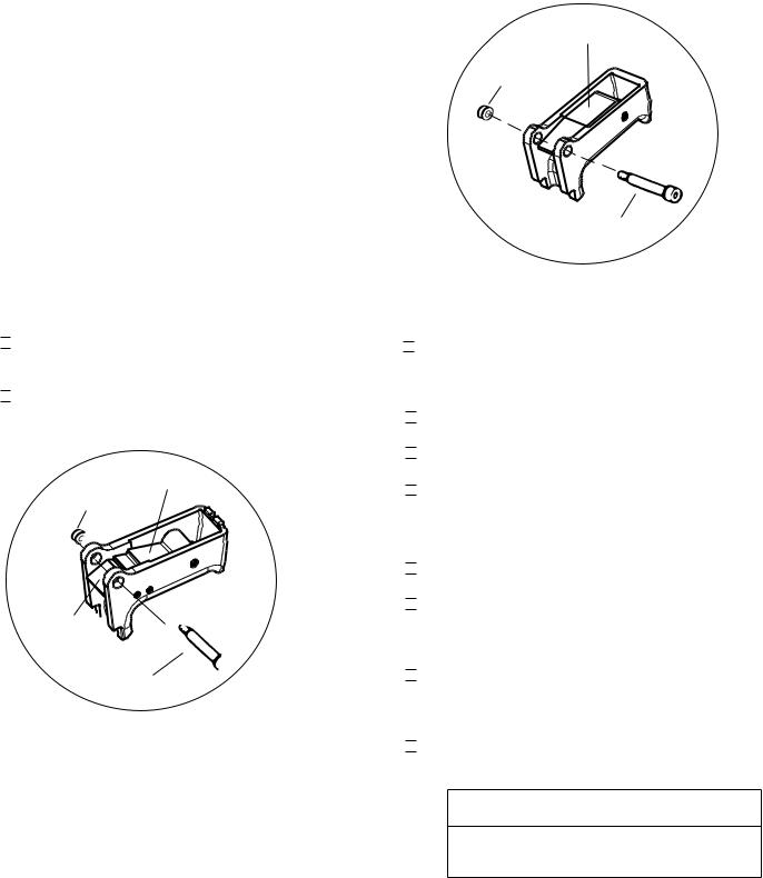
Sequential Operation - (Silver Trigger)
The tool is manufactured with a (Silver) sequential trigger installed.
The sequential operating trigger prevents successive or “bounce” driving.
■
 Depress the work contacting element and hold it against the work surface before pulling the trigger.
■
 After each fastener is driven, completely release the trigger and lift the tool from the work surface.
Sequential Lever
Grommet
 Sequential
Trigger
Sequential 

Actuator
Trigger Pin
#501039
Contact Trip (Bounce) Trigger Operation
(Orange Trigger)
The trigger kit (#501048) allows successive or “bounce” driving.
Bottom Trip Lever
Grommet
 Contact
Trigger
Trigger Pin
#501048
Precision Placement Driving
■
 Grasp the tool handle firmly and place the bottom of the work contacting element firmly against the workpiece until it is completely depressed.
■
 Squeeze the trigger to drive the fastener.
■
 Lift the tool from the workpiece.
■
 Repeat the procedure for the next fastener.
Successive (Bounce) Driving
■
 Grasp the handle firmly.
■
 Squeeze the trigger and move the tool along the workpiece with a bouncing motion, depressing the work contacting element at the points where you want to insert a fastener.
■
 Keep the trigger depressed and continue to bounce the work contacing element against the workpiece, positioning the tool above as carefully as possible.
■
 When the desired number of fasteners have been driven, release the tool trigger to avoid unintentional fastener discharge.
 WARNING
Do not clamp or hold the trigger with anything other than your hand.
6

AIR SYSTEMS
For air-powered tools to work their best, the air supply system must be properly installed and maintained regularly. A drawing in this section shows a properly installed air supply system. Handy checklists for installing and maintaining air supply systems follow.
Indoor Air System Installation -Be certain that:
 All pipes supplying air have a large enough inside diameter to ensure adequate air supply.
 The main supply pipe slopes down, away from the compressor (1/16 inch per foot).
 Air storage is provided along lengthy air lines.
 Pipe line branch outlets are at the top of the main pipe line.
 Cutoff valves are provided at each branch pipe line throughout the system.
 Water legs extend from the bottom of each branch line.
 A refrigerant-type dryer is installed on the system.
 Air hoses are kept as short as practical.
 A regular maintenance program is followed.
Outdoor Air System Installation -Be certain that:
 A moisture trap and a filter/regulator/lubricator are installed at the compressor.
 Air hoses and fittings are large enough so that air flow is not restricted. Minimum hose size is
3/8 inch ID with 1/2 inch ID hose used for any application over 25 feet.
 Air hoses are not longer than 150 feet.
 The air system is lubricated regularly.
 A regular maintenance program is followed.
Filter/Regulator/Lubricator Units
Filter/regulator/lubricator units that can supply enough air and protection for Paslode tools must meet the following specifications:
 Minimum 3/8 inch NPT port size .
 50 micron or fine filters.
 Regulated pressure from zero to 120 psi.
 Lubricators designed for low or changing airflow.
7

AIR SYSTEMS - Continued
Calculating Compressor Size
Use the air consumption chart in the Tool Schematic for each tool when calculating
the operating requirements for the tools. Paslode tools are designed to operate effciently between 80 and 120 psi and should never be operated at pressure greater than 120 psi.
The air consumption chart will help you find
the correct compressor size for your application that will quickly replenish tool air pres-
sure. To use the chart you will need to know
how many tools will be used and approximately how many fasteners will be driven
each minute by each tool onthe line. Using the equation:
Number of tools X average fasteners/minute/ tool X 1.2 (safety factor) X air consumption (scfm) @ pressure* (psi) = scfm required.
We can use the following example:
10 tools X 30 fasteners/minute/tool X 1.2 X 0.051scfm* (@100psi) = 18.36 scfm.
*This number is found in the Air Consumption Chart
In this example, using the air consumption chart we find that a compressor providing at least 19 scfm of air is required. Because in compressors approximately 1 hp is required to produce 4 scfm, a compressor of at least 5 hp is required.
Calculated Required Piping
For example, given a 20 hp electric compressor supplying approximately 80 cfm of air at 120 psi and a main supply pipe length of 350 feet, we see by the table the minimum main pipe inside diameter required for this application is 1-1/4 inch.
VOLUME |
|
LENGTH OF RUN (FT.) |
|
||
|
|
|
|
|
|
OF AIR |
50-200 |
290-500 |
500-1000 |
1000-2500 |
2500-5000 |
(CFM) |
|
|
|
|
|
|
NOMINAL PIPE DIAMETER (IN.) |
|
|||
|
|
|
|||
30-60 |
1 |
1 |
1¼ |
1½ |
1½ |
60-100 |
1 |
1¼ |
1¼ |
2 |
2 |
100-200 |
1¼ |
1½ |
2 |
2¼ |
2½ |
200-500 |
2 |
2½ |
3 |
3½ |
3½ |
500-1000 |
2½ |
3 |
3½ |
4 |
4½ |
Pneumatic System Maintenance
-Be certain that:
•Pneumatic fittings are tight and do not leak.
and ensure that automatic draining systems are operating correctly.
•Air lines are cleared to prevent freezing, especially in winter.
•Lubricator operation is checked regularly and ensure it has an adequate supply of lubricant. (Paslode Part No. 403720)
•Only regulated air is being used and that each regulator is operating properly.
8
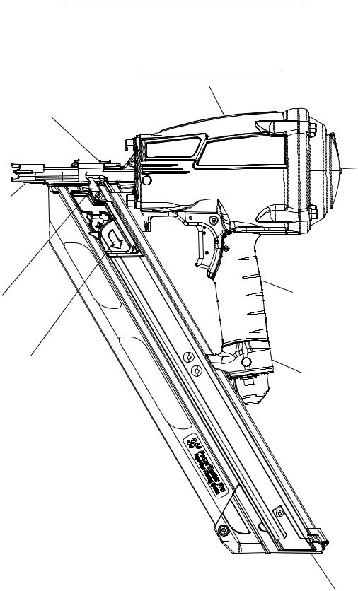
F-350P FEATURES & BENEFITS
Tool Less Depth of
Drive
Provides precise control
of nail depth without adjusting the compressor.
(on other side)
Agressive
Work Contact
Grabs the wood when toe nailing.
Lock Out
Eliminates blank
firing.
Bypass Follower
For fast 2-step loading.
Durable and Reliable Engine
For shot after shot performance.
P
Easy to Service to limit downtime.
Light Weight Design
Well balanced. Easy to manuever with less arm
fatigue.
Rafter Hook
Conveniently stowes the tool.
 In-line Magazine
for better balance
Rear Load Magazine
Holds 2 strips or 84 nails.
9

PARTS LEGEND |
PowerMaster Pro ™ |
F-350P, 515000 |
▲ 1 |
501043 |
1 |
T.H.S.C.S. 1/4 -20 x 1/2” |
2 |
501016 |
1 |
Air Deflector |
3 |
501300 |
4 |
S.H.C.S. 1/4-20 x 1-1/4” |
4 |
501017 |
1 |
Cap |
* 5 |
500461 |
1 |
O-Ring |
* 6 |
092042 |
2 |
O-Ring |
7 |
500407 |
1 |
Spring, Main Valve |
* 8 |
501001 |
1 |
Gasket, Cap |
9 |
406041 |
1 |
Retaining Ring |
10 |
500455 |
1 |
Upper Valve Piston |
11 |
401946 |
1 |
Seal, Main Valve |
*12 |
091208 |
1 |
O-Ring |
*13 |
401950 |
1 |
O-Ring |
14 |
500456 |
1 |
Lower Valve Piston |
*15 |
095432 |
1 |
O-Ring, Post |
16 |
500454 |
1 |
Post |
17 |
500453 |
1 |
Bumper, Post |
18 |
402906 |
1 |
B.H.S.C.S.10-32 x 5/8" |
*19 |
092971 |
1 |
O-Ring, Piston |
20 |
501337 |
1 |
Piston |
■ *21 |
501218 |
1 |
Driver Blade |
*22 |
402011 |
1 |
Seal Sleeve |
23 |
501283 |
1 |
Sleeve |
*24 |
500249 |
1 |
O-Ring, Sleeve |
*25 |
092235 |
1 |
O-Ring, Sleeve |
26 |
500779 |
1 |
Flange, Sleeve |
*27 |
501002 |
1 |
O-Ring, Midcheck |
*28 |
500866 |
1 |
Bumper |
29 |
500729 |
1 |
Blade Seal |
30 |
515017 |
1 |
Housing |
31 |
515013 |
1 |
Label,Housing Logo-Right |
32 |
515012 |
1 |
Label,Housing Logo-Left |
33 |
071297 |
3 |
Roll Pin |
*34 |
401598 |
1 |
Valve Body |
*35 |
097746 |
1 |
Valve Pin |
*36 |
092174 |
1 |
O-Ring, Valve Body |
*37 |
097748 |
1 |
Spring, Valve Pin |
38 |
402669 |
1 |
Pin Trigger |
39 |
402668 |
1 |
Retaining Ring |
*Denotes Normal Wear Items
**Make sure Warning Label (Part No. 515009) is properly affixed. Replace if necessary.
▲Apply Loctite 242 (Blue) Part No. 093500
■Apply Loctite (Green)
Denotes New Change
40 |
501039 |
1 |
Sequential Trigger |
41 |
515003 |
1 |
End Plug |
42 |
501299 |
2 |
S.H.C.S. 1/4-20 X 1” |
43 |
502930 |
1 |
Spring, Rafter Hook |
44 |
515005 |
1 |
Rafter Hook |
45 |
515018 |
1 |
Bushing, Rafter Hook |
46 |
444786 |
1 |
S.H.C.S. ,1/4-20 x 5/8” |
47 |
515002 |
1 |
Nose, 30º |
48 |
095417 |
4 |
Lockwasher 5/16 |
49 |
009016 |
4 |
S.H.C.S. 5/16-18 x 1” |
50 |
502014 |
2 |
Magazine Isolator |
51 |
515016 |
1 |
Compression Spring |
▲52 |
502050 |
1 |
Detent Body |
53 |
404361 |
1 |
Roll Pin 1/8” x 1/2” |
54 |
515004 |
1 |
Upper W.C.E. |
55 |
515010 |
1 |
Detent Spring |
56 |
502049 |
1 |
Detent Ball |
57 |
502299 |
1 |
Thumbwheel |
58 |
515006 |
1 |
Lower W.C.E. |
59 |
515008 |
1 |
1/4-20 x 3/8” |
** 60 |
515009 |
1 |
Warning Label |
61 |
442681 |
2 |
Locknut, 1/4-20 |
62 |
404325 |
2 |
Locknut #8-32 |
63 |
502029 |
1 |
Magazine Cap |
64 |
502031 |
2 |
S.H.C.S. 8-32 x 1/2” |
65 |
502038 |
1 |
S.H.C.S. 8-32 x 1" |
66 |
515020 |
1 |
Label, Magazine |
67 |
502017 |
2 |
B.H.C.S. 1/4”-20 X 3/4” |
68 |
502019 |
1 |
Follower Claw |
69 |
403796 |
1 |
Roll Pin |
70 |
502021 |
1 |
Lockout Bar |
71 |
511118 |
1 |
Follower Body |
72 |
502020 |
1 |
Follower Spring |
73 |
502025 |
1 |
Drum Pin Assembly |
74 |
502026 |
1 |
Negator Spring |
75 |
501008 |
1 |
Lever, Bottom Trip |
76 |
501009 |
1 |
Spirol Pin |
77 |
501010 |
1 |
Bump trigger |
|
AIR CONSUMPTION CHART |
||
- SCF/FASTENER |
|
|
|
CONSUMPTIONAIR |
|
|
.082 |
|
|
|
• SCF |
 WARNING
All parts must be periodically inspected and replaced if worn or broken. Failure to do this can affect the toolʼs operation and present a safety hazard.
AIR PRESSURE - PSIG
Note: For optimum performance Paslode recommends the use of a 3/8” Male fitting.
10
50 |
1 |
|
# |
|
|
|
|
|
|
2 |
|
160 |
3 |
|
# |
|
|
|
4 |
|
|
5 |
|
|
6 |
|
|
7 |
MAIN VALVE |
|
|
|
|
8 |
L |
|
ASSEMB Y |
|
|
|
500463 |
|
|
9 |
|
|
10 |
PowerMaster™ Pro
MODEL F-350P
PISTON DRIVER |
515000 |


 19
19


 20 ASSEMBLY
250 |
501519 |
|
|
# |
|
21 |
|
22
23


 24
24 


 25
25
|
75 |
OPTIONAL: |
|
|
BUMP |
||
|
|
||
|
|
TRIGGER |
|
77 |
76 |
ASSEMBLY |
|
501048 |
|||
|
|
|
11 |
|
12 |
14 |
|
13 |
|
|
|
|
|
15 |
16 |
|
|
|
|
|
17 |
|
|
18 |
20 |
|
|
# |
48
47
49
325 #
|
|
50 |
51 |
|
|
52 |
|
Upper |
|
Work Contact |
|
|
|
|
|
|
Assembly |
|
53 |
#515011 |
|
|
|
26 |
|
|
44 |
120 |
|
|
|
|
||
|
27 |
|
|
|
# |
|
|
|
|
46 |
|
|
|
|
|
43 |
45 |
|
28 |
|
|
|
|
|
29 |
|
|
|
42 |
|
|
|
6 |
160 |
|
|
|
|
|
||
|
30 |
|
# |
||
|
|
|
|||
|
|
|
|
||
|
|
|
|
41 |
|
31 |
|
|
|
|
|
32 |
|
|
|
38 |
|
|
37 |
|
40 |
|
|
|
|
36 |
|
|
|
|
|
|
|
|
|
33 |
|
|
33 |
39 |
|
34 |
35 |
|
15 |
||
|
|
||||
|
|
|
|
# |
|
|
|
|
|
62 |
|
|
|
|
|
|
|
59 |
|
61 |
|
|
|
160 |
|
|
|
|
|
|
|
|
|
64 |
|
# |
|
|
|
|
|
|
|
|
|
|
|
60 |
|
|
|
|
65 |
63
54


 55
55 


 56
56 


 57
57
58
Magaizine
Assembly
#515030
66
67 |
160 |
# |
|
|
69 |
68 |
|
73 |
70 |
|
74 |
71 |
64 |
72 |
|
15 |
|
|
|
|
|
|
# |
#Torque Values
IN/LBS
11

MAINTENANCE
Paslode® tools are built for ease of maintenance. A few simple details will assure trouble-free operation and long tool life. Anyone who uses or maintains the tool must read the safety and maintenance instructions. Study the schematic drawing before starting any repairs on the tool.
Air-operated tools must be inspected periodically, and worn or broken parts must be replaced to keep the tool operating safely and efficiently. Also the items on the maintenance chart must be checked often.
Cold Weather Care
When temperatures are below freezing, tools should be kept warm by any convenient, safe method. If this is not possible, the following procedure should be used to warm up the tools.
Reduce the regulated air pressure to 30 psi.
Remove all fasteners from the tool.
Collect an air line and blank fire the tool. The reduced air pressure will be enough to free-fire the tool. Slow speed operation tends to warm up the moving parts. Slowing up the piston helps the bumper and the O-rings to become springy.
Once the tool is warmed up, readjust the regulator to the proper working pressure and reload the tool.
Tool operators working outdoors or in unheated areas in extremely cold temperatures should also:
Use Paslode pneumatic oil with antifreeze in the lubricator, Part No. 219090 (8oz.)
Once a week, depending on the amount of tool use, take the tool apart and wash away any sludge with tool cleaner (Paslode Part No. 219348) to keep the tool operating efficiently.
Cleaning the air-operated tools with solvents removes the thin coating of grease applied to the cylinder wall and O-rings at the factory. To replace this coating of grease, use Chemplex grease (Paslode Part No. 403734).
Open the drain on the air compressor tank to drain any moisture at least daily in extremely cold or humid weather. A few ounces of anti-freeze in the tank will keep the air free of frost.
Testing the Tool After Servicing
After replacing any part or parts, it is important to check the tool for proper operation. This ensures that the tool was put together correctly, is safe to use, and will perform the job properly.
Ensure that all hardware is tight.
Ensure that the work contacting element is installed correctly in relation to the trigger, and that both parts move freely.
Ensure that the magazine is properly attached.
Ensure that the required safety information on the tool is legible.
Use only Paslode approved fasteners in the tool, and ensure that they are correct for the application.
Ensure that a male air fitting is securely connected to the tool.
Test the tool by driving fasteners into a workpiece identical to the tool's application.
Check the tool for air leaks during testing and for the proper sequence of operation.
Ensure that all fasteners are driven to the same depth and that the crown of the fastener is flush with the workpiece.
Tool Lubrication
It is most important that the tool be properly lubricated by keeping the air line lubricator filled and correctly adjusted. Without proper lubrication the tool will not work properly and parts will wear prematurely.
Use the proper lubricant in the air line lubricator. The lubricator should be of low air flow or changing air flow type, and should be kept filled to the correct level. Use only Paslode recommended lubricants. Substitutes may harm the rubber compounds in the tools O-rings and other rubber parts. Paslode Part No. 403720 is a pneumatic lubricating oil specially made for pneumatic applications. If a filter/regulator/lubricator is not installed on the air system, air operated tools should be lubricated at least once a day with 6 to 20 drops of oil, depending on the work environment, directly through the male fitting in the tool housing.
Most minor problems can be resolved quickly and easily using the maintenance table that follows. If problems persist, contact your Paslode dealer for assistance.
12

MAINTENANCE - Continued
 CAUTION
Disconnect the tool when performing repairs or clearing jams.
MAINTENANCE TABLE
ACTION |
|
WHY |
HOW |
|
|||
|
|
|
|
Drain air line filter(daily). |
|
Prevent accumulation of |
Open manual petcock (most |
|
|
mositure and dirt. |
air supply systems have such |
|
|
|
a valve). |
|
|
|
|
Keep lubricator filled. |
|
Keep tool lubricated. |
Fill with Paslode pneumatic |
|
|
|
tool lubricant. Part No. |
|
|
|
403720. |
|
|
|
|
Clean filter element-then blow |
|
Prevent clogging of filter with |
Wash with soap and water or |
air through filter in direction |
|
dirt. |
follow manufacturers instruc- |
opposite to normal flow. |
|
|
tions. |
|
|
|
|
Check that all screws on tool |
|
Prevent air leakage and pro- |
Check screws daily. |
are tight. |
|
mote efficient operation. |
|
|
|
|
|
Keep work contacting elelment |
|
Promote operator safety and |
Blow clean daily. |
working properly. |
|
efficient tool operation. |
|
|
|
|
|
Keep magazine and feeder |
|
Prevent jamming of fasteners. |
Blow clean daily. |
mechanism clean. |
|
|
|
|
|
|
|
Lubricate "O" rings that are |
|
Assure long life and proper |
Use Chemplex grease, Part |
replaced. |
|
operation of tool. |
No. 403734. |
|
|
|
|
Use only Paslode replacement |
|
Keep tool operating efficiently |
Order any repacement parts |
parts. |
|
and maintain Paslode tool |
needed from Paslode Dealer. |
|
|
warranty. |
|
|
|
|
|
13

OPERATOR TROUBLESHOOTING
 CAUTION
Disconnect the tool when performing repairs or clearing jams.
PROBLEM |
|
CORRECTIVE ACTION |
|
|
|
Fasteners will not drive completely into wood. |
|
Adjust work contacting element (retract length). |
|
|
Increase air pressure (do not exceed 120 psi). |
|
|
|
Fasteners penetrate properly during normal |
|
Increase air flow to tool -- use larger air lines |
operation, but won't drive fully at faster speeds. |
|
(3/8 inch ID minimum). |
|
|
|
|
|
Adjust work contacting element (extend length). |
Fasteners drive too deeply into wood. |
|
Reduce air pressure. |
|
|
|
|
|
|
|
|
Check magazine for proper fasteners. Magazine fol- |
Tools skips during operation - no fasteners are |
|
lower should slide freely. Clean as needed to remove |
driven from time to time. |
|
debris. |
|
|
Make sure correct fasteners are being used. |
|
|
Use fasteners that meet Paslode® specifications only. |
|
|
Increase air flow to tool -- use larger air lines |
|
|
(3/8 ID minimum). |
|
|
Adjust work contacting element where available. |
|
|
|
|
|
Check magazine for proper fasteners. Fasteners |
Tool operates, but no fasteners are driven. |
|
should slide freely with no follower pressure. |
|
|
Increase air pressure (do not exceed 120psi). |
|
|
|
Air leaks at cap when tool is connected to air. |
|
Tighten cap screws. |
|
|
|
|
14 |
|
|
|
|
|
|
|
30
14

TOOL WARRANTY
PAn Illinois Tool Works Company
155 Harlem Avenue
Glenview, IL 60025
MODEL F-350P
Framing Nailer
TOOL WARRANTY AND LIMITATIONS
Paslode warrants that newly purchased power fastening tools, parts and accessories will be free from defects in material and workmanship for the period shown below, after the date of delivery to the original user.
ONE-YEAR LIMITED WARRANTY
A one-year warranty will apply to all parts, except those which are specifically covered by an extended warranty.
FIVE-YEAR EXTENDED LIMITED WARRANTY
A five-year warranty will apply to all housing and cap assembly castings.
WARRANTY STATEMENT
Thiswarrantyislimitedtotoolssoldandservicerequested in the United States. To obtain information on warranty service in the United States, refer to the Service Center listing that was provided with your tool.
Paslode's sole liability hereunder will be to replace any part or accessory which proves to be defective within the specific time period. Any replacement part or accessory provided in accordance with this warranty will carry a warranty for the balance of the period of warranty applicable to the part it replaces. This warranty does not apply to part replacement required due to normal wear.
This warranty is void as to any tool which has been subjected to misuse, abuse, accidental or intentional damage, use with fasteners,not meeting Paslode specification, size, or quality, improperly maintained,repaired with other than genuine Paslode replacement parts,damaged in transit or handling, or which, in Paslode's opinion,has been altered or repaired in a way that affects or detracts from the performance of the tool.
PASLODE MAKES NO WARRANTY, EXPRESSED OR IMPLIED,RELATINGTOMERCHANTABILITY,FITNESS,OR OTHERWISE, EXCEPT AS STATED ABOVE, and Paslode's liability AS STATED ABOVE AND AS ASSUMED ABOVE is in lieu of all other warranties arising out of, or in connection with, the use and performance of the tool, except to the extent other wise provided by applicable law. PASLODE SHALL IN NO EVENT BE LIABLE FOR ANY DIRECT, INDIRECT, OR CONSEQUENTIAL DAMAGES, INCLUDING, BUT NOT LIMITED TO, DAMAGES WHICH MAY ARISE FROM LOSS OF ANTICIPATED PROFITS OR PRODUCTION, SPOILAGE OF MATERIALS, INCREASED COST OF OPERATION, OR OTHERWISE.
Paslode reserves the right to change specifications, equipment, or designs at any time without notice and without incurring obligation.
15
 Loading...