

Materials Testing Machine
7100 N
Load Cell
Leadscrews
Calibration
Rod and Nut
Load Bar
(crosshead)
Tensile Samples*
(60)
Sensor
Cable
Load Bar
Round Nut
Velcro® Loop
Material
Safety Shield (2)
Velcro® Hook
Material
WARNING: Provide proper eye
protection when using the Materials
Testing Machine or its Accessories.
Operate the Materials Testing Machine
behind protective Safety Shields.
Crankshaft
Base
USB Link*
*Items from the
ME-8230 Materials
Testing System
Materials Testing
Machine
Materials Testing System
Instruction Manual
012-13762D
ME-8236
Part of the
Comprehensive
ME-8244
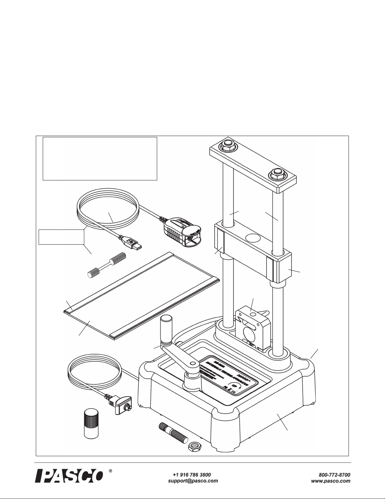
Materials Testing Machine Introduction
Materials Testing Machine (ME-8236)
.
Included Items Included Items
Materials Testing Machine Calibration Rod and Nut
Load Bar Round Nut Safety Shield (2)
Required Items*
PASCO Interface (PASPORT compatible)
PASCO Capstone Data Collection Software
*See the PASCO catalog or web site at
WWW.PASCO.COM
Materials Testing System (ME-8230)
The Materials Testing System includes the items in the
Materials Testing Machine PLUS an interface, software, and
sixty tensile samples as shown in Table 1.
Table 1: .Materials Testing System
Model Materials Testing System Items
ME-8236 Materials Testing Machine
PS-2100A USB Link
UI-5401 PASCO Capstone Software
ME-8231 Tensile Sample, Aluminum (10)
ME-8232 Tensile Sample, Brass (10)
ME-8233 Tensile Sample, Annealed Steel (10)
ME-8234 Tensile Sample, Acrylic (10)
ME-8235 Tensile Sample, Polyethylene (10)
Table 2: Comprehensive Materials Testing System
Model Comprehensive Materials Testing
System Items
ME-8230 Materials Testing System (MTS)
ME-8229 Materials Testing System Base
ME-8237 Materials Bending Accessory
ME-8238 Materials Coupon Adapter
ME-8239 Materials Shear Accessory
ME-8240 Materials Shear Samples (3 ea. of 3)
ME-8241 Materials Photoelasticity Accessory
ME-8242 Materials Structures Beam Adapter
ME-8245 Material Testing System Clevis Clip
ME-8246 MTS 10-32 Adapter
ME-8247 MTS Compression Accessory
ME-8248 MTS Compression Samples (20)
ME-8249 MTS Four-point Load Anvil
ME-6983 Cast Beam Spares Kit (10 molds)
ME-7011 Photoelastic I-Beams (24 each size)
ME-7012 Thin I-Beams (24 each size)
AP-8222* Coupons, Plastic (10 each of 4 types)
AP-8223* Coupons, Metal (10 each of 5 types)
*AP-8217A Replacement Test Coupons (Full Set) consists of the AP-8222 Plastic Coupons and the AP-8223
Metal Coupons.
ME-8243 Tensile Sample, Steel (10)
Comprehensive Materials Testing System (ME-8244)
The Comprehensive Materials Testing System includes all
the items in the Materials Testing System shown in Table 1
PLUS the accessories and other items shown in Table 2.
2
012-13762D
Introduction
The PASCO Materials Testing Machine is a device for measuring force and displacement for various materials as the
materials are stretched, compressed, sheared, or bent. The
Materials Testing Machine has a built-in load cell (strain
gauge transducer) capable of measuring up to 7100 newtons
(N) of force (1600 pounds), and an optical encoder module
that measures displacement of the load bar. A crank-and-gear
system raises or lowers the load bar on two leadscrews (also
known as power screws or translation screws). Force data
from the load cell and displacement data from the encoder
module can be recorded, displayed, and analyzed by a
PASCO Interface with PASCO Data Collection Software.
The sensor cable from the Materials Testing Machine connects to a PASPORT input port. (See the PASCO catalog or
web site at www.pasco.com for more information about
PASCO interfaces and data collection software.)
Model No.ME-8236 Materials Testing System
diameter = 3.3 mm
M12 x 1.75
19 mm
31.7 mm
NOTE: An Experiment Guide in electronic format
is available to download from www.pasco.com.
Enter “Materials Testing System” in the Search
window and look for the downloadable file(s)
under “Resources”.
Included Equipment
The Materials Testing Machine (ME-8236) includes a cali-
bration rod and nut, a load bar round nut, and a pair of safety
shields with Velcro® hook material.
Calibration Rod and Nut, Load Bar Round Nut, Safety Shields
• The calibration rod and nut can be used to determine
how much the Machine itself flexes as force is applied,
either in tension or in compression.
• The load bar round nut is used to connect one end of a
tensile sample to the load bar, for example, or can be
used to attach an accessory or adapter to the bottom side
of the load bar.
• The safety shields attach to the Velcro® loop material
on the front and back of the load bar.
Materials Testing System
The Materials Testing System (ME-8230) consists of the
Materials Testing Machine, plus a PASPORT interface called
the USB Link, PASCO Capstone Software, and sixty tensile
samples.
The USB Link connects the sensor cable of the Materials
Testing Machine to a USB port on a computer. The PASCO
Capstone software records, displays, and analyzes the data
from the Materials Testing Machine. (The software is available as an automatic digital download from PASCO.)
The tensile samples include four metals: aluminum, brass,
annealed steel, and steel and two plastics: acrylic and polyethylene, for tensile strength testing. There are ten samples
for each material.
Tensile Sample Information
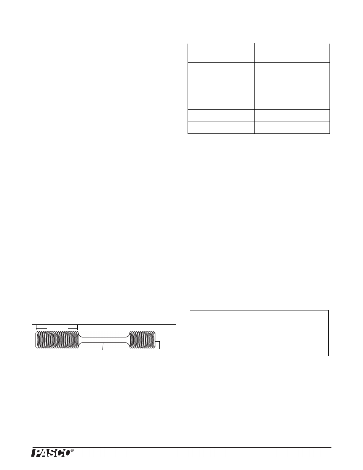
All the tensile samples (ME-8231 through ME-8235 and
ME-8243) have an overall length of 90 millimeters (mm) or
3.5 inches. The center section of each sample has an approx-
imate diameter of 3.3 mm or 0.131 inches. The threaded
ends are metric M12 x 1.75.
The table shows typical values.
Table 3: Typical Values
Material Tensile
Strength
Aluminum (2024-T3) 400 MPa 70 GPa
Brass (360) 500 MPa 80 GPa
Steel (1018) 700 MPa 200 GPa
Annealed Steel (1018) 400 MPa 200 GPa
Polyethylene 30 MPa 1 GPa
Acrylic 80 MPa 3 GPa
Young’s
Modulus
Accessories
Table 2 lists accessories and adapters that are included in the
Comprehensive Materials Testing System and are available
separately for the Material Testing Machine.
Other accessories and adapters are being developed.
Replacement Items
Also available separately are replacement items such as the
previously mentioned Tensile Samples, the Materials Shear
Samples (ME-8240) with nine metal rods (three each of aluminum, brass, and steel), the Plastic Coupons (AP-8222)
with ten samples each of four different plastics, the Metal
Coupons (AP-8223) with ten samples each of five different
metals, and the MTS Compression Samples (ME-8248).
About This Manual
The manual describes the basic setup of the Materials Testing Machine and the accessories and replacement items
included in the Comprehensive Materials Testing System. It
also describes the procedure for calibrating the Materials
Testing Machine using the included calibration rod and nut.
Experiment Guide
The tensile samples can be ordered separately.
Operation
Caution: Be sure to wear adequate eye protection when using the Materials Testing Machine or its accessories. Operate the Machine from behind a protective shield.
Basic operation involves mounting the Materials Testing
Machine firmly to a sturdy support, calibrating the Machine,
mounting the item to be tested onto the Materials Testing
Machine, connecting the Materials Testing Machine to an
012-13762D
3
Materials Testing Machine Operation
Storage Base
Sturdy support*
C-clamp*
Bolt*
Nut*
(*Items not included)
interface for data recording, and then turning the crank to
apply tension (stretching), compression (squeezing), bending, or shearing (cutting) forces to the test item.
ME-8229 MTS Storage Base
Secure the Materials Testing Machine
There are two holes through the base of the Materials Testing
Machine that can be used for bolting the Machine to a sturdy
support. The two 6 millimeter (mm) diameter holes are 15
centimeters apart; one on either side of the label.
Bolting the Machine will avoid the problem of the Machine
moving during a sample test. The Materials Testing System
Storage Base (ME-8229) is designed for two purposes: provide a sturdy base to which the Materials Testing Machine
can be bolted, and serve as a storage place for accessories,
tools, and other items in the Comprehensive Materials Testing System.
The Storage Base includes two screws and two washers and
has two threaded holes that match the spacing of the holes in
the Materials Testing Machine base. Place the Materials
Testing Machine on the Storage Base. Put the washers on the
screws, and put one screw through a hole in the base of the
Materials Testing Machine. Align the screw with the
threaded hole in the Storage Base, and tighten the screw
using your fingers. Put the other screw through the base and
align it with the other threaded hole. Use a 7/16 inch (11
mm) wrench to tighten the screws in place. Use C-clamps to
fasten the Storage Base to a sturdy table or bench. An option
is to bolt the Machine directly to a table or bench as shown.
The Storage Base has through holes at each of its corners.
PASCO Capstone data collection software includes a “calibration wizard” that allows the calibration information called a “compliance calibration” - for the Materials Testing
Machine to be stored for later use. (PASCO Capstone is provided in the ME-8230 Materials Testing System.)
Lab 02: Compliance Calibration Tutorial
NOTE: A PASCO Capstone workbook file about compliance
calibration is available to download from the PASCO web
site. Go to www.pasco.com and enter “Materials Testing
System” in the Search window. In the web page that opens,
select Materials Testing System. Click “Sample Labs” and
then download the ZIP file for Lab 02.
Information covered in the Compliance Calibration Tutorial
includes:
• How a compliance calibration works.
• How to create, save, and delete calibrations.
• Hints and practice in making an accurate calibration.
Reason for Calibration
The reason for the compliance calibration procedure is this:
if the Materials Testing Machine were perfectly rigid it
would give completely accurate measurements of force and
displacement. However, the Machine is not perfectly rigid.
To correct for the fact that the Machine “flexes” slightly, the
stiffness of the Machine is characterized and a calculation is
performed in the software to adjust the raw position data and
compute the displacement that is due only to the distortion of
the sample being tested. The compliance calibration information for the Machine can then be stored within the
Machine or stored in a Capstone file.
The calibration rod will not change shape significantly under
tension or compression. This means that any displacement
measured when the calibration rod is used is due to the flexing of the Materials Testing Machine itself.
Calibration Setup
The calibration rod and nut can be used for calibrating the
Materials Testing Machine for compression or tension. The
4
012-13762D
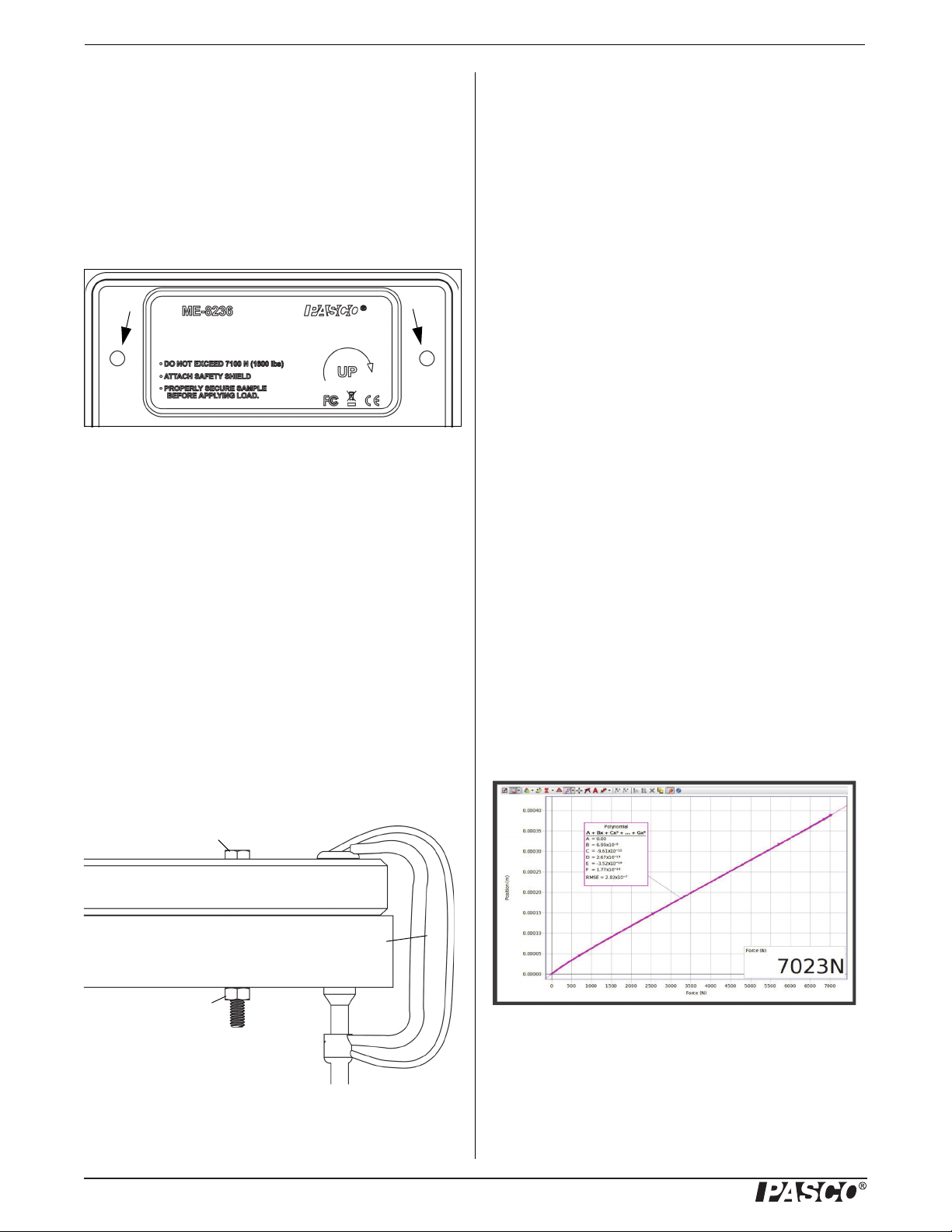
For example, the sample graph shows that the Machine
flexes 0.2 mm per 3,500 newtons of force when the calibration rod is stretched. If you use the Machine to stretch a
material sample, then the “flex” amount of 0.2 mm per 3,500
N would need to be subtracted.

Model No.ME-8236 Operation
Load Bar
Round
Nut
Load Bar
(crosshead)
Calibration
Rod
Crank
Handle
Load
Cell
Figure: Mount Calibration Rod for Tension
Calibration
Nut
Figure: Mount Calibration Rod and Nut for Compression
Load
Cell
Load Bar
(crosshead)
Sensor
Cable Plug
USB Link
Creating the Compliance Calibration Information
In the software, a polynomial curve fit is applied to the plot
of position versus force data. The coefficients of the polynomial curve fit are saved as the calibration information.
Once the compliance calibration is created for the Machine,
the software automatically subtracts the amount of “flex”
from the raw data. After the calibration information is stored
in the Machine, it cannot be edited. However, it you make a
new calibration, it will replace the stored calibration data.
Saving the Calibration Information
The calibration information can be saved in two ways: in the
Capstone file or in the Materials Testing Machine itself. If
the calibration information is saved in the Capstone file, it
can be used with any Materials Testing Machine. If the calibration information is stored in the Materials Testing
Machine, the information stays with that unit (even when it
is unplugged) and can be used with any Capstone file in the
future.
Mount the Calibration Rod for Tension
To mount the calibration rod for tension, screw the
short-threaded end of the rod into the top of the load cell.
Lower the load bar until the threaded part at the top of the
calibration rod goes through the hole in the load bar. Screw
the load bar round nut onto the top of the calibration rod.
section. Lower the load bar until the bottom of the load bar
rests on the top of the calibration nut.
Attach the Safety Shields
Attach the Velcro® hook material on the two safety shields
to the Velcro® loop material on the front and back of the
Load Bar. Adjust the position of the shields so that they will
block any fragments that may come from the calibration rod
in case it accidentally breaks.
Mount the Calibration Rod for Compression
To mount the calibration rod for compression, screw the
short-threaded end of the rod into the top of the load cell.
Screw the calibration nut onto the top threaded part of the
calibration rod until the nut is at the bottom of the threaded
Prepare to Record Calibration Data
Connect the plug on the sensor cable into a PASPORT interface, such as the USB Link (included in the Materials Testing System). Connect the interface to a USB port on a
computer.
See Appendix A for details of the Calibration Procedure.
After the Calibration Procedure is complete, return to this point.
Mount a Tensile Sample
Select a tensile sample to mount onto the Materials Testing
Machine. Put the end of the sample with the short threaded
section into the threaded hole in the top of the load cell.
Screw in the sample until the top edge of the short threaded
section is flush with the top of the load cell.
012-13762D
5

Materials Testing Machine Operation
Load Bar
Sample
Nut
Tensile
Sample
Crank
Handle
Load
Cell
Figure: Mount Tensile Sample
Loop
Material
for Safety
Shield
Load Bar
(crosshead)
Figure: Materials Bending Accessory
Load
Cell
Plunger
Sample
Anvil
Anvil
Crank
Handle
Sample
Nut
Base
Load Bar
(crosshead)
Lower the load bar so that the longer threaded section of the
sample goes up through the hole in the center of the load bar.
Adjust the load bar until the bottom edge of the longer
threaded section is flush with the bottom of the load bar.
While holding the tensile sample so it does not turn, screw
the sample nut onto the longer threaded section until the
sample is held tightly in place.
bar using the sample nut. The base for the adjustable anvils
is screwed onto the top of the load cell.
The spacing between the two triangular support anvils can be
adjusted. Use the hex key to loosen the screws holding the
anvils and slide them closer together or farther apart. Tighten
the screws securely.
Use the sample nut to secure the plunger in place on the load
bar. Remove the screws from the base for the anvils and
align the base on top of the load cell. Use the screws and the
hex key to fasten the base in place.
Place a sample for testing on the two support anvils.
Attach the Safety Shields
Attach the Velcro® hook material on the two safety shields
to the Velcro® loop material on the front and back of the
Load Bar and adjust the position of the shields if needed.
Apply a Force
Turn the crank counterclockwise to apply a compression
force through the plunger onto the sample.
Attach the Safety Shields
Attach the Velcro® hook material on the two safety shields
to the Velcro® loop material on the front and back of the
Load Bar. Adjust the position of the shields so that they will
block any fragments that may come from the sample.
Record Data
Prepare PASCO Capstone software to record data. (If there is
a stored calibration file that is to be used, select it in the
“Calibration” window.)
Start data recording. Turn the crank in a clockwise direction
to apply a tension force to the tensile sample. Observe the
graph display of force and position. (Note that the default for
the Materials Testing Machine in the software shows force
and position as ‘negative’ when a tension force is applied.
See Appendix A for information about changing signs.))
When the sample breaks, or is stretched the maximum
amount, stop data recording.
Materials Bending Accessory (ME-8237)
The Materials Bending Accessory includes a plunger, a
adjustable support anvils, and a small hex key (allen
wrench). The plunger is mounted on the bottom of the load
Materials Coupon Adapter (ME-8238)
The Materials Coupon Adapter includes two coupon clamps,
a “tee-handle”, and a 3/8” socket (12 point). One clamp fits
in the load cell and the other fits in the load bar. They can be
used to mount a plastic coupon (AP-8222) or metal coupon
(AP-8223) onto the Materials Testing Machine for testing of
tensile strength.
6
012-13762D

Model No.ME-8236 Operation
Movable
Jaw
Fixed
Jaw
Hex Nut
Upper
Clamp
Lower
Clamp
Metal
Coupon
Plastic
Coupon
Figure: Materials Coupon Adapter
Front
Piece
Back
Piece
0.067”,
1.7 mm
0.099”,
2.5 mm
0.161”,
4.0 mm
0.130”,
3.3mm
Mounting
Screws
Hold the upper clamp so it remains parallel to the lower
clamp and tighten the sample nut slightly to remove any
slack in the coupon.
Attach the Safety Shields
Attach the Velcro® hook material on the two safety shields
to the Velcro® loop material on the front and back of the
Load Bar and adjust the position of the shields if needed.
Loosen but do not remove the hex nut on each clamp. The
jaws of the clamp are spring loaded, so the moveable jaw
will separate from the fixed jaw. Screw the clamp with the
shorter threaded section into the load cell. Put the threaded
section of the other clamp up through the hole in the load
bar, and use the sample nut to hold the upper clamp. NOTE:
Do not completely tighten the sample nut yet.
Materials Shear Accessory (ME-8239)
The Materials Shear Accessory consists of two pieces of
hardened steel - a front piece and a back piece - held together
by a pair of permanent screws, and a package of Materials
Shear Samples. The front piece can slide vertically relative
to the back piece, which is designed to be mounted on the
load cell using an included hex key (allen wrench). The two
pieces have pairs of matching holes with four different diameters to fit a variety of samples for testing. The hole diameters are approximately 1/16”, 3/32”, 1/8”, and 5/32”. The
Materials Shear Samples includes three 1/8” diameter rods
each of three metals: aluminum, brass, and mild steel.
NOTE: Do not use a sample with a hardness greater
than mild steel.
Carefully place one end of a coupon between the jaws of the
bottom clamp. While holding the moveable jaw to keep it
aligned with the fixed jaw, use the tee-handle and socket to
tighten the hex nut. CAUTION: Each coupon is fragile. Do
not let the moveable jaw twist out of alignment with the
fixed jaw as this might bend the coupon.
Turn the upper clamp so that it is aligned with the lower
clamp. Adjust the position of the load bar so that you have
room to carefully put the other end of the coupon between
the jaws of the upper clamp. Keep the movable jaw aligned
with the fixed jaw so that the coupon does not twist or bend.
Once again, tighten the hex nut.
Use the two mounting screws and the included hex key
(allen wrench) to attach the back piece of the Materials Shear
Accessory to the top of the load cell. Note that when the
front piece is raised by hand as far as it will go, the holes in
the front piece align with the matching holes in the back
piece.
Insert the test sample through the pair of holes that best
match the diameter of the sample. Use a sample that is long
enough so that it extends about 1/4” (6 mm) beyond the front
and back pieces. Doing this makes it easier to remove the
sample remnants from the accessory after the test.
012-13762D
7

Materials Testing Machine Operation
Materials Shear
Accessory
Figure: Materials Shear Accessory
Polarizer
Hook
Material
Figure: Polarizers on Load Bar
Figure: Materials Structures Beam Adapter
Clamp for
Load Bar
Clamp for
Load Cell
To place the polarizers on the Load Bar, align a polarizer
with the strips of loop material on the front of the Load Bar
and press the edges of the polarizer so that the hook material
adheres to the loop material. Repeat the process with the second polarizer on the other side of the load bar.
Adjust the position of the load bar so that it rests on the top
surface of the front piece.
Attach the Safety Shields
Place a light source so that it shines through the polarizers
from behind.
Attach the Velcro® hook material on the two safety shields
to the Velcro® loop material on the front and back of the
Load Bar. Adjust the position if needed.
Materials Structure Beam Adapter (ME-8242)
Materials Photoelasticity Accessory (ME-8241)
Clear plastic samples that are viewed through crossed polarizers reveal patterns of different colors that show stress distribution. The Materials Photoelasticity Accessory is
designed to demonstrate the photoelastic phenomenon in
clear plastic samples.
The Accessory consists of two rectangles of polarizer material that can be attached to the Velcro® loop material on the
Load Bar of the Materials Testing Machine.
The PASCO Structures System includes a variety of beams
that can be used with the Materials Testing Machine. The
beams are models of I-beams and other structure elements.
The Materials Structure Beam Adapter is designed to hold a
structures beam so that it can be tested under tension and
compression.
The Materials Structures Beam Adapter consists of two
clamps and an included hex key. Each clamp has two jaws,
one of which can be removed so that an end of a structures
beam can be put in the clamp. The threaded ends of the two
clamps fit in the load bar and load cell of the Materials Testing Machine.
8
Use the included hex key to remove the screws that hold the
two parts of the clamp together. Put the ends of a structures
beam, such as a #3 I-Beam, into one part of each clamp, and
then use the screws to reattach the other part of each clamp.
012-13762D

Model No.ME-8236 Operation
Structures
Beam
Remember to attach the two safety shields to the Load Bar.
MTS 10 – 32 Adapter (ME-8246)
There are several devices used in material testing that hold
materials in place and have a threaded 10 - 32 hole designed
for mounting the device on a materials tester, such as the
Materials Testing System. The Materials 10 - 32 Adapter is
designed to connect devices with a threaded 10 - 32 hole to
the Load Bar and Load Cell of the Materials Testing
Machine.
The 10 - 32 Adapter with the longer larger diameter threaded
section is mounted in the Load Bar of the Materials Testing
Machine, and the 10 - 32 Adapter with the shorter threaded
section and the hex nut is mounted in the top of the Load
Cell.
Screw the clamp with the short threaded end into the top of
the load cell, and put the other clamp through the hole in the
load bar. Use the sample nut to secure the clamp to the load
bar.
Attach the Safety Shields
Attach the Velcro® hook material on the two safety shields
to the Velcro® loop material on the front and back of the
Load Bar. Adjust the position if needed.
MTS Clevis Clip (ME-8245)
The Materials Testing System Clevis Clip is designed to tensile test a wide variety of samples that have hooked ends or
through holes. The diameter of each clevis pin is 0.187 in
(0.47 cm). Each pin contains a pair of small, spring-loaded
spheres near its end to keep the pin from slipping out of the
clip.
The Clevis Clip with the longer threaded section is mounted
in the Load Bar of the Materials Testing Machine, and the
Clevis Clip with the shorter threaded section and the hex nut
is mounted in the top of the Load Cell.
MTS Compression Accessory (ME-8247)
The Materials Compression Accessory is designed to work
with the Materials Testing Machine to compress samples.
The Compression Accessory consists of two one inch (2.54
cm) diameter platforms that provide a sturdy base for compression samples.
The Materials Compression Accessory includes twenty
Materials Compression Samples (ME-8248). The polyethylene cylinders are approximately 0.5 in (1.3 cm) in diameter
and 0.75 in (2 cm) long.
MTS Four-point Load Anvil (ME-8249)
The Materials Four-point Load Anvil extends the capabilities of the Materials Bending Accessory. When used with the
Bending Accessory and the Materials Testing Machine, data
to find the flexural plastic modulus and the modulus of rup-
012-13762D
9

Materials Testing Machine Operation
Rebar Member
Mold
#3 Beam
#4 Beam
ture of tested samples can be measured, recorded, and analyzed.
Cast Beam Spares Kit (ME-6983)
The Cast Beam Spares Kit includes 30 “Rebar” members
and 10 “molds”. A Cast Beam consists of a beam that is a
model of the reinforcement bars (“rebar”) used in construction, and a mold that is used to produce a model of a beam of
reinforced “concrete” or prestressed “concrete”. A mixture
of fine sand, plaster, and water is poured into the assembled
rebar beam and mold. After the mixture hardens and the
mold is removed, the beam can be used as a #4 beam in any
PASCO Structure Set, or tested on the Materials Testing
Machine.
Photoelastic I-Beams (ME-7011)
The Photoelastic I-Beams are similar to the #3 I-Beams and
#4 I-Beams that are part of the PASCO Structures Systems
(such as the Truss Set, ME-6990). However, the Photoelastic
I-Beams differ in that they are clear polycarbonate plastic
and do not have any holes in the web area of the beam. They
can be mounted on the Materials Testing Machine using the
Materials Structures Beam Adapter. When viewed with the
Materials Photoelasticity Accessory, the distribution of stress
in the beams can be studied.
The set includes twenty-four each of the two sizes of
I-beams. The #3 I-Beam is 11.5 cm long, and the #4 I-Beam
is 17 cm long.
Thin I-Beams (ME-7012)
The Thin I-Beams set consists of 48 thin I-Beams of two
sizes: #3 Beam (24) and #4 Beam (24). The beams are like
those in the PASCO Structures Systems, but there are no
holes in the web area. Therefore, when used with the Materials Testing Machine, the test results are more like the results
would be for the type of metal I-Beam used in construction.
Maintenance
The illustration shows a Cast Beam with the Materials Testing Machine and the Four-point Load Anvil attached to the
Bending Accessory.
Regular maintenance for this equipment is minimal. The
leadscrews need to be kept clean, and they may need to be
re-lubricated at some point. Use a food grade anti-seize
grease containing PTFE (polytetrafluoroethylene, commonly
known as Teflon®).
If problems arise with the Materials Testing Machine, notify
PASCO scientific. It is not recommended that you attempt to
fix this equipment yourself. (See the Technical Support
information at the end of this manual.)
Specifications
Item Description
Load Cell capacity 7100 N (1600 lbs)
Load Cell maximum 100% of capacity
Experiment Guide
NOTE: An Experiment Guide in electronic format is available to download from www.pasco.com. The Experiment
Guide includes information about the calibration procedure
and also describes the available Capstone Workbook files for
the Materials Testing Machine.
Enter “Materials Testing System” in the Search window and
look for the downloadable file(s) under “User Resources”.
10
The list of Capstone Workbook files for the Materials Testing Machine includes the following. Each lab is available as
012-13762D

Model No.ME-8236 Technical Support
a downloadable ZIP folder containing a PDF setup file and a
Capstone data file:
Sample Labs
• Lab 01: Intro to Materials Tester
• Lab 02: Compliance Calibration Tutorial
• Lab 03: Tensile Testing - Brass
• Lab 04: Young’s Modulus
• Lab 05: Tensile Testing - Annealed Steel
• Lab 06: Tensile Testing - Metal Coupons
• Lab 07: Tensile Testing - Plastic Coupons
• Lab 08: Tensile Testing - Plastic Samples
• Lab 09: Three Point Bending
• Lab 10: Round Rod Bending
• Lab 11: Bend Testing Beams
• Lab 12: Tensile Testing Beams
• Lab 13: Column Buckling and Slenderness Ratio
• Lab 14: Euler Column Buckling
will be recycled in a manner that protects human health and
the environment. To find out where you can drop off your
waste equipment for recycling, please contact your local
waste recycle/disposal service, or the place where you purchased the product.
The European Union WEEE (Waste Electronic and Electrical Equipment) symbol
(to the right) and on the product or its
packaging indicates that this product must
not be disposed of in a standard waste container.
Technical Support
For assistance with any PASCO product, contact PASCO at:
Address: PASCO scientific
10101 Foothills Blvd.
Roseville, CA 95747-7100
Phone: +1 916-462-8384 (worldwide)
877-373-0300 (U.S.)
E-mail: support@pasco.com
Web www.pasco.com
For the latest information about the Materials Testing
Machine or the replacement items and accessories, so to the
PASCO web site at www.pasco.com and enter the model
number in the search window.
Limited Warranty For a description of the product warranty, see the
PASCO catalog. Copyright The PASCO scientific Instruction Manual
is copyrighted with all rights reserved. Permission is granted to
non-profit educational institutions for reproduction of any part of this
manual, providing the reproductions are used only in their laboratories and classrooms, and are not sold for profit. Reproduction under
any other circumstances, without the written consent of PASCO scientific, is prohibited. Trademarks PASCO, PASCO Capstone,
PASPORT, SPARK Science Learning System, SPARK SLS, and
SPARKvue are trademarks or registered trademarks of PASCO scientific, in the United States and/or in other countries. For more information visit www.pasco.com/legal.
Product End of Life Disposal Instructions:
This electronic product is subject to disposal and recycling
regulations that vary by country and region. It is your
responsibility to recycle your electronic equipment per your
local environmental laws and regulations to ensure that it
012-13762D
11

Materials Testing Machine Appendix A: Calibration
Materials Testing Machine
icon
Properties
icon
Appendix A: Calibration
General Information: Pre-Calibration
Lab 02: Compliance Calibration Tutorial
REMINDER: A PASCO Capstone workbook file about compliance calibration is available to download from the PASCO web
site. Go to www.pasco.com and enter “Materials Testing System” in the Search window. In the web page that opens, select
Materials Testing System. Click “Sample Labs” and then download the ZIP file for Lab 02.
Information covered in the “Lab 02 Compliance Calibration Tutorial” includes:
• How a compliance calibration works.
• How to create, save, and delete calibrations.
• Hints and practice in making an accurate calibration.
Optional: Change Sign
NOTE: The default for the Materials Testing Machine in the software is
a negative value for force and position as ‘negative’ when a tension
force is applied. Although it is possible to use the Materials Testing
Machine with negative values for force and position, it is easier to
change the sign convention to be positive while you use the “Calibration Wizard” for the calibration procedure.
• To change the sign for the force and position data, click the “Hardware Setup” icon in the Tools palette.
• In the Hardware Setup window, click the “Properties” icon (shaped
like a gear wheel) to open the “Properties” window for the Materials Testing Machine.
• In the “Properties” window, note that the default for the
“Change Sign” is an un-checked box. This means there is a
positive value for both position and force when the Load Bar is
moving down, as in a compression.
• If you want positive values for both position and force when
the Load Bar is moving up, as in tension, click the check box
for “Change Sign”.
• Click OK to close the “Properties” window.
• Click the “Hardware Setup” icon to close the “Hardware
Setup” window.
Prepare to use the software to calibrate the Material Testing
Machine.
12
012-13762D

Model No.ME-8236 Appendix A: Calibration
Calibration Procedure
The following steps describe how to use the “calibration wizard” in PASCO Capstone to create a compliance calibration for
the Materials Testing Machine. Please preview the steps to become familiar with the procedure before doing the calibration.
Step One: Choose the Type of Measurement to Calibrate
In the Capstone software, select the “Calibration” icon ( ) in the
Tools palette to open the “Calibration” window.
There are two types of calibration for the Materials Testing Machine.
One is a simple calibration of the force measured by the Load Cell. The
other, the default choice, is “Materials Testing System: Compliance
Calibration”. Use this choice to setup the program to automatically
make corrections on position data.
• Click Next to show Step Two, the “Choose Calibration Action” menu.
Step Two: Choose Calibration Action
There are several choices in “Create New Calibration” that allow you to create, select, save, modify, and delete calibrations.
• Create New Calibration: This is the default choice. In this selec-
tion, the “calibration wizard” will take you through the steps
needed to create and save a new compliance calibration. This
includes prompting you to install the calibration rod (Step Three),
record a data run on the graph provided (Step Four), and create a
polynomial curve fit (Step Five) that will be stored as your compliance calibration.
The following is a description of the other Calibration Action choices.
• Use Calibration: If the text window below “Use Calibration” is
blank, it means that there is no “active” calibration being used.
However, if any compliance calibrations have been saved previously in this Capstone file, they will be displayed in the pull down
menu (click the down arrow). (The previously saved compliance
calibration “7000 N cal (Tue Dec 17 11:37:30 2013)” is shown as
an example.) If you select a previously saved compliance calibration from the pull down menu, it becomes the “active” calibration.
When you click Finish, the selected calibration will be used to
make the compliance correction to any future data you collect.
012-13762D
13

Materials Testing Machine Appendix A: Calibration
• Import Calibration From Sensor: If any compliance calibrations
have been stored in the Materials Testing Machine (the “Sensor”),
they will be displayed in the pull down menu. (The stored calibration “7100N 100N pre (Tue Feb 25)” is shown as an example.) If
you click Finish, the selected stored calibration will be imported
and added to the list for use. It will also become the “active” calibration. NOTE: Calibrations stored in the Material Testing
Machine (the Sensor) can not be used or renamed until they are
imported.
• Use Raw Values: If this choice is selected and you click Finish,
the selected compliance calibration (if any) is temporarily disabled. Any future data collected will not be adjusted. NOTE: The
calibration is still saved.
• Manage Existing Calibration: If this choice is selected and you
click Next, Step 3 is revealed as shown in the illustration. Your
choices are: Delete Calibration, Rename Calibration, or Save Calibration in Sensor (the Materials Testing Machine).
• If you wish to delete a calibration, select the calibration you want
to delete from the pull down menu and then select “Delete Calibration”. Click Finish to delete the calibration.
• If you select “Rename Calibration” (the default choice) and click
Next, a text window opens and you can enter a new name for a
calibration. ADVICE: Create a name that includes the maximum
force used. It is also helpful to record any pre load that is used.
Click Finish after entering a name.
• If you select “Save Calibration in Sensor” and click Next, the window shows “Store Calibration” and “Choose which calibration to
overwrite”. The default view of the pull down menu shows
“Empty Calibration 0”. If you click Finish, the calibration you
wish to store will take the place of “Empty Calibration”.
CAUTION: Only four calibrations can be stored in the Materials Testing Machine. If you already have four calibrations stored, and you wish
to store another calibration, you will be prompted to select which calibration you want to replace.
NOTE: You can have any number of calibrations saved as part of the
Capstone file. When you name your calibration as in Step Six “Name
the calibration” (see below), create a name that includes the maximum
force used. It is also helpful to record any pre load that is used. When
the saved Capstone file is re-opened, the calibrations will still be available.
• After you have made your Calibration Action choice (REMINDER: “Create New Calibration” is the default), click Next
to show the illustration in Step Three, “Install the calibration rod”.
14
012-13762D

Model No.ME-8236 Appendix A: Calibration
Position (m)
Force (N)
Digits display of
Force (N)
Position versus
force data
Polynomial curve fit
Step Three: Install the Calibration Rod
The ‘calibration wizard” changes to show an illustration about how to
install the calibration rod.
In addition to the illustration, a Graph display of Position (m) versus
Force (N) opens. A Digits display of Force (N) is part of the Graph display.
• Click Next to show Step Four: “Record a smooth data run”.
Step Four: Record a Smooth Data Run
NOTE: To make a calibration that will accurately correct for compliance, it is necessary to calibrate the Materials Testing Machine over the
same range of force and the same conditions you expect to use when
you are testing your samples.
• Click Record and collect a smooth run of position versus force
data.
• When the data collection is finished, click Stop.
REMINDER: If the run of data is not smooth, delete the run and try again.
NOTE: A Polynomial curve fit is automatically applied to the run of position versus
force data.
• Click Next to open Step Five, “Polynomial Fit”.
012-13762D
15

Materials Testing Machine Appendix A: Calibration
Step Five: Polynomial Fit
NOTE: By default, the “Show Curve Fit Editor” window is open in the
“Polynomial Fit” window. The Curve Fit Editor window shows the
default values for the coefficients of the polynomial.
In the Curve Fit Editor window you can change the “Number of Terms”,
enter an “Initial Guess” for each coefficient and lock or unlock a coefficient value.
• If the message “Curve fit was successful” is shown, click Next to
open Step Six, “Name the calibration”.
NOTE: If the curve fit was not successful, use “trial-and-change” in the
Curve Fit Editor to adjust the coefficients until the curve fit is successful.
Click “Update Fit” to determine if the new coefficients made a better
curve fit
Step Six: Name the Calibration.
• Type a name for the calibration in the text area. (Example names
might be “Calibration 7000” or “Tension Calibration”.)
• Click Finish to store the calibration as part of the Capstone file.
Finishing Step
NOTE: The “Calibration” window goes back to Step One. When you
click Next, the “Choose Calibration Action” window (Step Two) will show a menu of the saved and/or stored calibration(s).
• Click “Use Calibration” and select a specific saved calibration
from the pull down menu below “User Calibration”, or click
“Import Calibration From Sensor” to load a selected stored calibration from the pull down menu below “Import Calibration From
Sensor”.
• Click Finish. The “Calibration” window goes back to Step One.
• Click the “Calibration” icon in the Tools palette to close the “Calibration” window. Save the Capstone file for future use.
16
012-13762D

Model No.ME-8236 Appendix A: Calibration
• From the “File” menu, save the Capstone file for future use.
012-13762D
17

Materials Testing Machine Appendix B: “Seating” a Test Sample and Setting a Pre-Load
Appendix B: “Seating” a Test Sample and Setting a Pre-Load
In the following procedure, a test sample is stretched and relaxed to properly “seat” the sample (remove any slack) and a
pre-load is set.
“Seat” the Sample
1. Mount a test sample onto the Materials Testing Machine. Make sure that the Load Bar Round Nut is slightly loose and not
applying a force on the test sample.
2. In the Capstone software, set up a Graph display of Position versus Force, and a Digits display of Force.
3. Click Record.
• NOTE: If the position and force data on the graph are not zero, check the “Properties” window in the “Hardware Setup”
panel. The check box for “Zero Sensor Measurement at Start” should be checked.
4. Turn the crank clockwise about a quarter of a turn and note that the position and force data are being plotted on the Graph
display.
5. With data still being recorded, slowly turn the crank back counter-clockwise. Watch the Digits display, and turn the crank
to reduce the force to between 10 and 20 N. Don’t let the force go back to zero.
6. Turn the crank clockwise to increase the force as before. Notice how the second plot of data looks on the graph compared
to the first. If the second plot of data “tracks” on top of the first plot, then the sample is properly “seated” and you can
click Stop. If not, repeat the process of applying force and then unloading the force.
• NOTE: Usually it is necessary to load and unload the system several times to remove all the slack and “seat” the test sample.
7. When two consecutive plots of data track on top of each other, the test sample is properly “seated”. Click Stop.
Set a Pre-Load
8. Click Record to begin collecting data and increase the force back up to 100 N. Click Stop and DO NOT change the crank
position. Since the Materials Testing Machine is set to automatically zero itself the next time you start recording data, this
puts a pre-load of 100 N on the sample, which results in better data.
18
012-13762D
 Loading...