

Page 1

Instructions
Demonstrations
Experiments
Sample Data
Sine Wave Generator
Instruction Manual
No. 012-08678A
WA-9867
Page 2

Sine Wave Generator Model No. WA-9867
Contents
Introduction. . . . . . . . . . . . . . . . . . . . . . . . . . . . . . . . . . . . . . . . . . . . . . . . . . . . . . . . . . . . . . . . 3
Setup . . . . . . . . . . . . . . . . . . . . . . . . . . . . . . . . . . . . . . . . . . . . . . . . . . . . . . . . . . . . . . . . . . . . . 4
Operation. . . . . . . . . . . . . . . . . . . . . . . . . . . . . . . . . . . . . . . . . . . . . . . . . . . . . . . . . . . . . . . . . . 5
Specifications. . . . . . . . . . . . . . . . . . . . . . . . . . . . . . . . . . . . . . . . . . . . . . . . . . . . . . . . . . . . . . 9
Operational Flow Chart . . . . . . . . . . . . . . . . . . . . . . . . . . . . . . . . . . . . . . . . . . . . . . . . . . . . .10
Applications . . . . . . . . . . . . . . . . . . . . . . . . . . . . . . . . . . . . . . . . . . . . . . . . . . . . . . . . . . . . . . 11
Experiment 1:
Standing Waves In Strings . . . . . . . . . . . . . . . . . . . . . . . . . . . . . . . . . . . . . . . . . . . . . . . . . . 15
Experiment 2:
Resonance Tubes. . . . . . . . . . . . . . . . . . . . . . . . . . . . . . . . . . . . . . . . . . . . . . . . . . . . . . . . . . 21
Experiment 1:
Teachers’ Notes–Standing Waves in Strings. . . . . . . . . . . . . . . . . . . . . . . . . . . . . . . . . . . . 27
Experiment 2:
Teachers’ Notes–Resonance Tubes. . . . . . . . . . . . . . . . . . . . . . . . . . . . . . . . . . . . . . . . . . . 29
Safety. . . . . . . . . . . . . . . . . . . . . . . . . . . . . . . . . . . . . . . . . . . . . . . . . . . . . . . . . . . . . . . . . . . . 31
Technical Support . . . . . . . . . . . . . . . . . . . . . . . . . . . . . . . . . . . . . . . . . . . . . . . . . . . . . . . . . 31
Copyright and Warranty Information . . . . . . . . . . . . . . . . . . . . . . . . . . . . . . . . . . . . . . . . . . 31
Page 3

Model No. WA-9867 Sine Wave Generator
Power
Supply
Sine Wave
Generator
Sine Wave Generator
Model No. WA-9867
Included Eq ui pm e n t Replace m ent Pa rt Nu m ber
Sine Wave Generator
Power Supply
Suggested Accessories Model Number
String V ibrato r
Economy Wave Driver
Mechanical Wave Driver
Open Speaker
Economy Resonance Tube
Banana Patch Cords
WA-9867
540-057
WA-9858
WA-9854
SF-9324
WA-9900
WA-9495
SE-7123
Introduction
The PASCO Sine Wave Generator supplies adjustable-frequency AC power for applications such
as driving speakers, wave drivers and string vibrators. The digital display and easy-to-use
frequency and amplitude controls make this unit ideal for student labs.
The additional features of Auto Play and Advanced Mode with Record and Playback enhance
classroom demonstrations and permanent displays requiring automated signal variation.
The Sine Wave Generator outputs AC power at up to about 10 volts amplitude (20 V peak-topeak) and 1 amp. The output frequency, adjustable in increments of 0.1 Hz, ranges from 1 Hz to
800 Hz.
®
3
Page 4
Sine Wave Generator Setup
Power Input
On/Off
Switch
Increment
Keys
Amplitude
Knob
Fine Frequency
Knob
Course Frequency
Knob
Display
Output Jacks
Setup
Input Power
Connect the included power supply to the power input of the Sine Wave Generator. Slide the
ON/OFF switch to the right to turn it on.
Output Power
Connect a device such as a speaker or string vibrator to the output jacks of the Sine Wave
Generator with a pair of 4 mm banana patch cords. Both jacks produce AC signals with opposite
phases, so polarity is not important. (Note that the outputs do not float with respect to ground.)
If the Sine Wave Generator is connected to a short-circuit, the unit’s short-circuit protection will
shut off the output. Remove the short and cycle the input power to restore it.
Mounting and Storage
You can use the built-in clamp on the back of the unit to mount the Sine Wave Generator on a
vertical rod, as shown. Rod mounting makes the display more visible for demonstrations and
allows you to position the controls
conveniently when you set up an
experiment.
For storage, recessed dimples in the top
of the case align with the feet on the
bottom, allowing several units to be
stacked as shown.
4
®
Page 5
Model No. WA-9867 Operation
Operation
In addition to the description given here, there is a complete operational flow chart on page 10.
Manual Control
Amplitude
Adjust the amplitude of the output signal with the Amplitude knob. The amplitude range is
approximately 0 V to 10 V.
Frequency
Set the output frequency with the Coarse and Fine Frequency knobs (labeled “1.0” and “0.1”).
The LED display indicates the frequency to 0.1 Hz resolution. When the Sine Wave Generator is
first turned on, it outputs the default frequency of 100 Hz. You can adjust the output signal from 1
Hz to 800 Hz.
The Frequency knobs are mechanical encoders with 24 discrete detents, or clicks, per revolution.
One click of the Fine knob changes the frequency by 0.1 Hz. One click of the Coarse knob
changes the frequency by 1.0 Hz if the knob is turned slowly, or 4.0 Hz if the knob is turned
quickly. This allows you to change the frequency more quickly over a large range.
You can also use the Up and Down Increment keys to change the frequency. Each quick press of
the Up or Down key changes the frequency by the stored increment. By default the increment is
100 Hz. To change the stored increment, see the Increment Keys section below. (If you press and
hold the Increment keys, a different function will occur, so only use quick presses to change the
frequency.)
This following sections describe how to change the stored frequency increment and program the
Sine Wave Generator to play automatic sequences of notes. If you would like to skip to some
practical demonstrations, see the Applications se ction on page 11.
Incremen t Key s
The Up and Down arrow keys have multiple functions. The Increment function is activated by a
single quick press and release of either key . Other functions are activated when you press and hold
the keys. For example, to implement the Play function you would press and hold the Up arrow
key for about 1 second. The instructions may read, “press and hold the Play key,” or, “press the
Up Increment key.” Both refer to the same key , but different functions. The labels below the keys
(Store/Exit and Play) indicate the press-and-hold functions of the keys.
Changing the Output Frequency by the Stored Increment
Each quick press of the Up or Down Increment key changes the output frequency by the amount
stored as the increment. The default increment (when unit is initially turned on) is 100 Hz. Thus, a
single press of the Up Increment key will add 100 Hz to the output frequency. Try this:
®
5
Page 6

Sine Wave Generator Operation
1. Turn the Sine Wave Generator on (if it is already on, turn it off for a second, then back on).
The initial output frequency is 100 Hz.
2. Press the Up Increment key. The frequency changes to 200 Hz. Press it again and it changes to
300 Hz. Press the Down Increment key and the frequency changes back to 200 Hz.
3. Use the Frequency knobs to change the frequency to 220 Hz.
4. Press the Up Increment key; the frequency changes to 320 Hz.
5. Press the Up Increment key several more times so that the output is 720 Hz. Additional
presses of the Up Increment key will do nothing because the output will not exceed 800 Hz.
Setting the Stored Increment
The harmonics of a resonating device (such as a vibrating string or tube) are usually spaced at
equal frequency increments. It is useful to set the Sine Wave Generator’s stored increment to
match your device.
The label below the Up arrow key reads Store/Exit. When you press and hold this key, it will
function as a Store key; the stored increment will change to the value on the display (which is the
output frequency). Try this:
1. Use the Increment keys and the Frequency knobs to set the output to 120 Hz.
2. Press and hold the Store key. After 1 second the display will blink and you can release the key .
The stored increment is now 120 Hz.
3. Press the Up Increment key a few times; the frequency changes by 120 Hz with every press.
This value will remain stored until a new value replaces it or the unit is turned off.
Auto Play
In Auto Play mode you can program the Sine Wa ve Genera tor to scan automatically through the
harmonics of a device.
Setup
The label below the Up arrow key reads Play. When you press and hold it, this key will start
automatic play. Try this:
1. Set the stored increment to 120 Hz (as described above).
2. Use the Amplitude knobs to change the output frequency to 60 Hz.
3. Press and hold the Play key. The di splay will blink to show you that Auto Play has st arted, and
you can release the key .
4. The Sine Wave Generator will play the starting note (60 Hz), then increment to the next notes
(180 Hz, 300 Hz, 420 Hz, etc.), playing each note for 1.5 seconds. You can use the Amplitude
knob to adjust the output.
6
®
Page 7
Model No. WA-9867 Operation
Duration of Each Note
While in Auto Play mode, you can use the Frequency knobs to change the duration of each note.
By default, each note is played for 1.5 seconds. If you turn the Course (1.0) knob one click
clockwise, it will increase the duration by 1 se cond. The display will switch over to show the
duration (in seconds), and then switch back to showing the frequencies. One click of the Fine
(0.1) knob will change the duration by 0.1 second. The duration can be set from 0.1 to 99.9
seconds.
Wrap Around
Auto Play will continue to increment the frequency until it reaches the maximum (up to, but not
over 800 Hz); then it will wrap around and start the sequence again. To make Auto Play wrap
around at a lower frequency, press and hold the Play key when the sequence is at the highest note
that you want. (The display will blink after 1 second to indicate that you can release the key.)
Exit Auto Play
To stop Auto Play, press and hold the Store/Exit key. (The display will blink after 1 second to
indicate that you can release the key. ) The Sine Wave Generator will return to normal mode, and
the output frequency will return to the original starting frequency.
Advanced Mode: Record and Playback
In Advanced Mode you can set, store and play back a sequence of up to 80 notes. The Sine Wave
Generator will record the frequency and amplitude of each note. Advanced Mode is espec ially
useful when demonstrating resonance in vibrating strings because it allows you to set the optimal
amplitude and frequency for each harmonic.
This mode is a hidden sub-layer so as to not confuse the student with extra complexity in normal
lab use. It is intended for the teacher’s use in demonstrations. Although it is “hidden”, it is easily
accessible and straightfor war d to use.
Entering Advanced Mode
Press and hold both arrow keys simultaneously (as shown) until
the display changes to indicate the number of recorded notes. If
no sequence is stored it will display “0.”
After entering Advanced Mode there are 3 options:
Exit: Press and hold the Store/Exit key to leave Advanced
Mode and return to normal mode.
Play the St ored Sequence: Press and hold the Play key. The
Sine Wave Generator will enter Playback Mode and play the
sequence of recorded notes. (If there is no recorded seque nce, this action will exit Advanced Mode.)
Enter Record Mode: Press and hold both keys simultaneously again to enter Record Mode. The
display will show “0” (to denote tha t it has cleared out the previously stored sequence) and begin to
flicker to indicate that the unit is in Record Mode.
®
7
Page 8

Sine Wave Generator Operation
Record a Sequence of Notes
In Record Mode the display will always flicker. When you enter Record Mode, the display shows
the output frequency. Connect the apparatus (such as a string vibrator with a string) to the Sine
Wave Generator so that you can tune the frequency and amplitude for each harmonic.
1. Enter Record Mode (see above).
2. Set the frequency and amplitude of the first note in the sequence (usually the fundamental
resonance frequency of the apparatus).
The Frequency knobs and the Increment keys function as norma l. Use only a quick press and
release to implement the up and down increment. The increment value is what it was set to
before you entered Advanced Mode.
3. Press and hold the Store key until the display changes; for a moment the display will show the
total number of stored notes, then return to showing the frequency.
4. Adjust the frequency and amplitude for the next note in the sequence and return to step 3.
5. After you have stored the entire sequence of notes, press and hold the Play key until the
display stops flickering. The Sine Wave Generator will switch to Playback M ode and begin to
play the sequence that you have recorded.
While you are recording a sequence, be careful not to make a mist ake. There is no way to edit a
note in the sequence after it has been stored. When you enter Record Mode, all previous notes are
erased and you start over. Once you have stored a note, you can not change or erase it.
Playback of Stored Notes
With the Sine Wave Generator in Playback Mode and playing the stored sequence, you have
several options:
Amplitude: If you turn the Amplitude knob all the way up, the unit will play ba ck the stored
notes exactly as you recorded them. If you turn the knob down, it decreases all of the stored notes
by the same proportion.
Duration: You can use the Frequency knobs to change the duration of every note. The default
duration is 1.5 seconds. The Course (1.0) knob changes the duration by 1 second per click, the
Fine (0.1) changes the duration by 0.1 second per click. If you exit Advanced Mode and return
later, the Sine Wave Generator will remember the previous duration setting.
Pause: A quick press of the Down arrow key pauses the playback of the stored sequence. To
resume playback, press and hold Play until the display blinks.
While paused, a quick press of the Up or Down arrow key will cause the next or previous note in
the sequence to play.
While paused, you can use the Frequency knobs to vary the output frequency. This is useful to
show what happens when the driving frequency is slightly off resonance. Changing the frequency
with the knobs while playback is pause d does not change the stored notes.
8
®
Page 9
Model No. WA-9867 Specifications
Sequence S tar t-over: When the last stored note has been played, the Sine Wave Generator wraps
around and starts over with the first note. At any time during play mode, a quick press of the Up
arrow key will cause the sequence to start over with the first note.
S top Playback: Pre s s and hold the Store/Exit key to return to normal mode. The output
frequency will be set to the stored increment.
The sequence remains in storage. You can go back to Advanced Mode and play the sequence
again, even if you turned the unit off and unplug it in the interim.
Specifications
Frequency 1 to 800 Hz
Adjustable in 0.1 Hz increments
Output DC coupled push-pull
Short-circuit protected
Amplitude 0 to 10 V peak (approx.)
Current >1 A into 8 Ω load
Memory Up to 80 stored notes
Display 4 digit LED
Input Power 100–240 VAC, 50/60 Hz
Dimensions 12 × 11 × 5 cm
(not including separate power supply)
®
9
Page 10
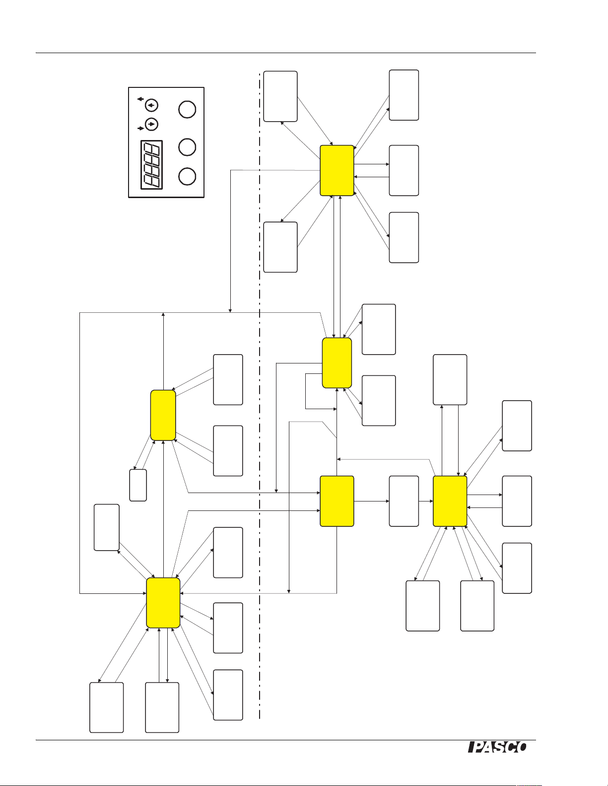
Sine Wave Generator Operational Flow Chart
NORMAL
SHOW
NUMBER OF
STORED
NOTES
INC/DEC
FREQ by 1
INC/DEC
FREQ by 0.1
FREQ 0.1
FREQ 1.0,
(SLOW)
INC/DEC
FREQ by 4
FREQ 1.0,
(FAST)
MEMORIZE
INCREMENT
HOLD
STORE/EXIT
INCREASE
FREQ BY
INCREMENT
DECREASE
FREQ BY
INCREMENT
PRESS PLAY
PRESS STORE/
EXIT
HOLD PLAY
INC/DEC
INTERVAL BY
1 SEC
INC/DEC
INTERVAL BY
0.1 SEC
FREQ 1.0 FREQ 0.1
MAX INTERVAL = 99.5 SEC MIN INTERVAL = 0.5 SEC,
DISPLAY TEMPORARILY SHOWS INTERVAL, THEN
REVERTS TO NORMAL OPERATION.
PAUSED PLAY
PRESS STORE/EXIT
HOLD PLAY
STORED
NOTES:
BACKWARDS
STORED
NOTES:
FORWARDS
PRESS
PLAY
PRESS
STORE/EXIT
AMPLITUDE RAMPS DOWN
AND UP AT CHANGE OF
FREQUENCY. RAMP TURNED
OFF FOR INTERVALS LESS
THAN 1 SECOND.
RECORD
MODE
CLEAR
STORED
VALUES
ADJUST
FREQUENCY AND
AMPLITUDE THEN:
HOLD STORE/EXIT
SHOW #
STORED
NOTES X sec
IF NUMBER OF STORED NOTES
EXCEEDS CAPACITY (80), LAST
NOTE DISPLAYED THEN
RETURN.
HOLD PLAY
AND STORE/EXIT
HOLD PLAY
HOLD
STORE/EXIT
WA-9867 SINE WAVE GENERATOR OPERATIONAL FLOW CHART
Rev 1.01
05/07/2004
SET MAX
FREQ.
HOLD
PLAY
AUTOPLAY:
INCREMENT
PLAY STORED
NOTES
(STORED NOTES > 0)
(STORED NOTES= 0)
HOLD PLAY
AND STORE/EXIT
HOLD PLAY AND
STORE/EXIT
INITIAL PRESS 'FREEZES'
DISPLAY. IF HELD, MAX
FREQUENCY IS SET.
FREQUENCY
REVERTS TO POINT
WHEN NORMAL
MODE EXITED
RETURN AFTER DELAY
DISPLAY FLICKERS IN RECORD MODE
HOLD STORE/EXIT
HOLD
STORE/EXIT
INC/DEC
FREQ by 1
INC/DEC
FREQ by 0.1
FREQ 0.1
FREQ 1.0,
(SLOW)
INC/DEC
FREQ by 4
FREQ 1.0,
(FAST)
INC/DEC
FREQ by 1
INC/DEC
FREQ by 0.1
FREQ 0.1
FREQ 1.0,
(SLOW)
INC/DEC
FREQ by 4
FREQ 1.0,
(FAST TURN)
BUTTON PLAYS
FORWARDS
STORED NOTES.
INCREASE
FREQ BY
INCREMENT
DECREASE
FREQ BY
INCREMENT
PRESS PLAY
PRESS
STORE/EXIT
STORE/EXIT PLAY
AMPLITUDEFREQUENCY
0.11.0
INCREMENT
WA-9867
BUTTON PLAYS
BACKWARDS
THROUGH STORED
NOTES.
INC/DEC
INTERVAL BY
1 SEC
INC/DEC
INTERVAL BY
0.1 SEC
FREQ 1.0 FREQ 0.1
HOLD PLAY
HOLD PLAY AND STORE/EXIT
HOLD STORE/EXIT
MAX INTERVAL = 99.5 SEC, MIN INTERVAL = 0.1 SEC; DISPLAY TEMPORARILY
SHOWS INTERVAL, THEN REVERTS TO NORMAL OPERATION.
ADVANCED
OPERATION
BASIC OPERATION
AMPLITUDE RAMPS
DOWN AND UP AT
CHANGE OF
FREQUENCY. RAMP
TURNED OFF FOR
INTERVALS LESS
THAN 1 SECOND.
NOTES:
1. "PRESS" means press the button then immediately release.
2. "HOLD" means press and hold the button(s) for at least one
second, then release. In most modes the display will "blink" after
the key has been held for the required amount of time.
PRESS PLAY
SEQUENCE
RESTART
THROUGH
Operational Flow Chart
10
®
Page 11

Model No. WA-9867 Applications
Applications
Open Resonance Tube
The resonance tube shown here has both ends open and a fundamental resonance frequency of
120 Hz. It is set up to be driven by a speaker and Sine Wave Generator. (Note the position and
angle of the speaker relative to the end of the tube.)
There are two ways to use the Auto Play feature to demonstrate resonance. With the first method,
the Sine W a ve Generator steps through a series of resonance frequencies. With the second
method, it scans slowly through a frequency range encompassing one resonance frequency.
Method 1: Step Through the Harmonics
1. Using the Frequency knobs, set the output to the fundamental resonance frequency of the tube
(120 Hz in this case). Listen carefully while adjusting to determine the optimal driving
frequency.
2. Press and hold the Store/Exit key to store the increment as 120 Hz (or whatever the current
output frequency is).
®
11
Page 12

Sine Wave Generator Applications
3. Press and hold the Play key to start Auto Play. The speaker will play 120 Hz, 240 Hz, etc., up
to 720 Hz, then repeat.
4. You will notice that the tube does not resonate well above a certain frequency. When the
sequence reaches the highest note that you want, press and hold the Play key. Thereafter, the
sequence will wrap around after that note.
5. Adjust the amplitude of the driving signal with the Amplitude knob.
6. Adjust the duration of each note with the Course (1.0) and Fine (0.1) Frequency knobs.
7. To stop Auto Play, press and hold the Store/Exit key .
Method 2: Scan Across the Fundamental Resonance
1. Using the Frequency knobs, turn the frequency down to 1 Hz. (If you turn the Coarse knob
slowly , the frequency changes by 1 Hz per click; if you turn it faster , the frequency changes by
4 Hz per click.)
2. Press and hold the Store/Exit key to store the increment as 1 Hz.
3. Use the Frequency knobs again to set the fr equency to 110 Hz.
4. Press and hold the Play key to start Auto Play. When the frequency reaches 130 Hz, press and
hold the Play key again to make the frequency wrap around and repeat.
5. Use the Frequency knobs to adjust the duration of each note to about 0.5 seconds.
The Sine Wave Generator will now repeatedly scan across the resonance at 120 Hz. Remove the
tube to show that the sound level from the speaker is constant, then put the tube back in place to
show how much louder it gets each time the frequency is near resonance.
Closed Resonance Tube
1. Replace the tube from the previous demonstration with a tube that has one closed end, one
open end, and a fundamental resonance of 60 Hz.
2. Use the Frequency knobs to set the output frequency to the fundamental resonance, then press
and hold Play to make the speaker play 60 Hz, 120 Hz, 180 Hz, etc.
3. Why doesn’t the tube resonate at 120 Hz? This is a good way to demonstrate that closed pipes
only play the odd harmonics.
You can also set up the Sine W a ve Generator to play only the odd harmonics.
1. Using the frequency knobs, set the f r equency to 120 Hz.
2. Press and hold the Store/Exit key to store the increment as 120 Hz.
3. Use the frequency knobs again to set the initial frequency to 60 Hz.
4. Press and hold the Play key; the speaker will play 60 Hz, 180 Hz, 300 Hz, etc.
12
®
Page 13

Model No. WA-9867 Applications
Vibrati n g Str ing
This automated display of a vibr ating string is a good example of where the Advanced Mode is
useful. With a 2 meter elastic cord and the PASCO String Vibrator (WA-9857), you can easily get
a standing wave of 10 segments or more.
In this demonstration, the Sine Wave Generator scans through the resonance frequencies so that
you see the string vibrate with 1, 2, 3, etc., segments. The generator is mounted vertically to
display the driving frequency. Once set up, it will cycle indefinitely, making for an engaging
permanent display.
For best results, use Advanced Record and Playback Mode. If you were to use the regular Auto
Play mode, there are two problems that would occur. First, the optimal driving-signal amplitude
for the lower harmonics would be insufficient to excite visible vibrations at the higher harmonics.
Second, it would be difficult to perfectly tune a single increment value so that the driving
frequencies for all 10 harmonics were exactly correct.
Both of these problems are solved with Advanced Mode, since you store both the frequency and
amplitude of each note in the sequence. Because the Sine Wave Generator is working as you
record the sequence, you can finely tune the dr iving signal for maximum effect at every harmonic.
See the Advance Mode section on page 7 for programing instructions, and the PASCO String
V ibr ator manual for mechanical details of the setup.
®
13
Page 14

Sine Wave Generator Applications
14
®
Page 15

Model No. WA-9867 Sine Wave Generator
Experiment 1:
Stand ing Waves In Strings
Equipment Part Number
Sine Wave Generator
String V ibrato r
Braided String (inelastic, low-density)
Yellow Braided Cord (inelastic, higher-density)
Elastic Cord
Banana Patch Cords (qty. 2)
Clamp or other device of securing the St ring Vibrator
Super Pulley
Mounting Rod for Super Pulley
Universal Table Clamp
Mass and Hanger Set
Balance
Tape Measure
Strobe (optional)
WA-9867
WA-9857
SE-80 50 or similar
ME-9409 or similar
Part o f WA-9857, SE-9409 or similar
SE-71 23 or similar
SE-72 86 or similar
ME-9450
SA-9242
ME-9472 or similar
ME-8967 or similar
SE-8765A or similar
SE-8712A or similar
SF-92 11 or similar
Introduction
The general appearance of waves can be shown by means of standing waves in a string. This type
of wave is very important because most vibr ations of extended bodies, such as the prongs of a
tuning fork or the strings of a piano, are standing waves. In this experiment you will discover how
the speed of the wave in a vibr ating string is affected by the density of the string, the st retching
force and the frequency of the wave.
Theory
Standing waves (stationary waves) are produced by the interference of two traveling waves, both
of which have the same wavelength, speed and amplitude, but travel in opposite directions
through the same medium. The necessary conditions for the production of standing waves can be
met in the case of a stretched string by having waves set up by some vibrating body, reflected at
the end of the string and then interfe ring with the oncoming waves.
®
15
Page 16

Sine Wave Generator Standing Waves In Strings
L
String
String
Vibrator
Hanging
Mass
Pulley
A stretched string has many natural modes of vibration (three examples are shown above). If the
string is fixed at both ends then there must be a node at each end. It may vibrate as a single
segment, in which case the length (L) of the string is equal to 1/2 the wavelength (λ) of the wave.
It may also vibrate in two segments with a node at each end and one node in the middle; then the
wavelength is equal to the length of the string. It may also vibrate with a larger integer number of
segments. In every case, the length of the string equals some integer number of half wavelengths.
If you drive a stretched string at an a rbitrary frequency, you will probably not see any particular
mode; many modes will be mixe d together. But, if the driving frequency, the tension and the
length are adjusted correctly, one vibrational mode will occur at a much greater amplitude than
the other modes.
For any wave with wavelength λ and frequency f, the speed, v, is
(eq. 1) v = λ f
In this experiment, standing waves are set up in a stretched string by the vibrations of an
electrically-driven string vibrator. The arrangement of the apparatus is shown below. The tension
in the string equals the weight of the mass suspended over the pulley. You can alter the tension by
changing the mass. You can adjust the amplitude and frequency of the wave by adjusting the
output of the Sine Wa ve Generator , which powers the string vibrator.
16
®
Page 17

Model No. WA-9867 Experiment 1: Standing Waves In Strings
Setup
1. As shown in the picture, clamp the Sine W ave Generator and pulley about 120 cm apart.
Attach about 1.5 m of braided string to the vibrating blade, run it over the pulley , and hang
about 150 g of mass from it.
2. Measure from the knot where the string attaches to the string vibrator to the top of the pulley.
This is distance L. (Note that L is not the total length of the string, only the part that is
vibrating.)
3. Turn on the Sine Wave Generator and turn the Amplitude knob all the way down (counter-
clockwise). Connect the Sine Wave Generator to the string vibrator using two banana patch
cords. Polarity does not matter.
Part I:
Wavelength and Frequency
Procedure
1. Set the Amplitude knob about midway. Use the Coarse (1.0) and Fine (0.1) Frequency knobs
of the Sine Wave Generator to adjust the vibrations so that the string vibrates in one segment.
Adjust the driving amplitude and frequency to obtain a large-amplitude wave, but also check
the end of the vibrating blade; the point where the string attaches should be a node. It is more
important to have a good node at the blade than it is to have the largest amplitude possible.
However, it is desirable to have a large amplitude while keeping a good node.
2. Record the frequency. How much uncertainty is there in this value? How much can you
change the frequency before you see an effect?
3. Repeat steps 1 and 2 for a standing wave with two segments. The string should vibrate with a
node at each end and one node in the center.
4. How is the frequency of the two-segment wave related to the frequency of the one-segment
wave? Calculate the ratio of the frequencies. Is the ratio what you would expect?
5. With the wave vibrating in two segments, the length of the string, L, is one wavelength
(L = λ). Does it look like one wavelength? Since the string vibrates up and down so fast, it is
hard to see that when one side is up, the other is down. Examine the vibration of the string
®
17
Page 18

Sine Wave Generator Standing Waves In Strings
using a strobe light if one is available. Adjust the strobe frequency to be near the frequency of
the Sine Wave Generator. The string will look like it is moving in slow motion.
6. Try touching the stri ng at an anti-node. What happens? Try touching the string at the central
node. Can you hold the string at the node and not significantly effect the vibration?
7. What was the wavelength when the string was vibrating in one segment? Use Equation 1 to
calculate the speed of the one-segment wave.
8. Calculate the speed of the two-segment wave. How do these to values compare? Are they
about the same? Why?
9. Adjust the frequency so that the string vibrates in three segments. Has the velocity changed?
Does the speed of the wave depend on the wa velength and the frequency?
Further Investigations
Changi ng Tension
1. Adjust the frequency so that the string vibrates in two segments. Now, without changing the
frequency, decrease the mass on the hanger until the string vibrates in 4 segments. (You may
have to use small masses to get a good waveform. Remember that it is more important to have
a good node at the end of the blade than to have the biggest amplitude possible.)
2. Record the total hanging mass, including the mass hanger. Calculate the ratio of the new mass
to the original mass. Why is the ratio not 2? You will learn more about the relationship
between wave velocity and string tension in Part II of this lab.
Changing Length
1. Return the mass to its original amount. Set the frequency to a value between the frequencies
that produced waves of two and three segments. Adjust the frequency so that no particular
standing waveform is present.
2. Unclamp the string vibrator and slowly move it towards the pulley. (Do not let go of the string
vibrator without clamping it to the table again.)
3. Without changing the driving frequency or the hanging mass decrease the length of vibrating
string until it vibrates in two segments. Adjust the position to get the best node at the blade, as
before. (If the hanging mass touches the floor, reattach it to the string higher up.)
4. Measure the new wavelength and calculate the speed of the wave. Is it about the same as
before? Does the speed of the wave depend on the length of the string?
18
®
Page 19

Model No. WA-9867 Experiment 1: Standing Waves In Strings
v
F
µ
---=
L
l
String
String
Vibrator
Hanging
Mass
Pulley
f
2 4g
µL
2
----------
m=
Part II:
Wave Speed and String Density
Theory
As stated in Equation 1, the speed of any wave is related to the wavelength and the frequency. For
a wave on a string, the speed is also related to the Tension (F) in the string, and the linear density
(µ) of the string, as shown by
(eq. 2)
The linear density (µ) is the mass per unit length of the string. The Tension (F) is applied by the
hanging a mass (m), and is equal to the weight (mg) of the hanging mass.
For this part of the expe riment, you will always adjust the frequency so that the wave vibrates in
four segments, thus the length of the string will always equal two wavelengths (L =2λ).
In this case F = mg and L =2λ; these equations can be combined with equations 1 and 2 to show
(eq. 3)
where:
f = driving f r equency of the Sine Wave Generator
g = acceleration due to gravity
m = total hanging mass
L = length of string (vibrating part only)
µ = linear density of the st ring (mass/length)
®
19
Page 20

Sine Wave Generator Standing Waves In Strings
slope
4g
µL
2
----------
=
% Deviation
Measured Actual–
Actual
---------------------------------------------
100%×=
Procedure
1. Clamp the String V i brator about 120 cm from the pulley . Hang about 50 g from the string over
the pulley . Measure from the knot at the vibrating blade to the top of the pulley. This is the
distance L. (Note that L is not the total length of the string, only the part that is vibrating.)
2. Record the total hanging mass, including the mass hanger.
3. Adjust the frequency of the Sine Wave Generator so that the string vibrates in four segments.
As before, adjust the driving amplitude and frequency to obtain a large-amplitude wave, and
clean nodes, including the node at the end of the blade. Record the frequency.
4. Add 50 g to the hanging mass and repeat steps 2 and 3.
5. Repeat at intervals of 50 g up to at least 250 g. Record your data in a table.
6. Make a graph of Frequency-squared, f
2
, versus hanging mass, m. (The units will be easier to
work with later if you graph the mass in kilograms.) Is the graph linear?
7. Find the slope (including uncertainty) of the best-fit line through this data.
8. As you can determine from Equation 3, the slope of the f2 vs. m graph is:
From the slope of your graph, calculate the density (µ) of the string. What is the uncertainty?
9. Determine the actual density of the string by m easuring the mas s of a known length. If you do
not have a balance readable to 0.01 g, use several meters of string.
10. Compare the density that you measured in step 8 to the actual density that you determined in
step 9. Calculate the percent deviation.
Further Investigations
20
1. Repeat the procedure using the yellow cord. Put the data from the string and cord on the same
graph to show the difference in their densities.
2. Repeat the procedure with elastic cord. The density is muc h larger, so put the data on a
separate graph. Look carefully at the graph. Is it linear like the first two? Calculate the density
using both the minimum and maximum slopes.
3. Measure how much the elastic cord stretches when you place the maximum mass on the
hanger. Based on the unstretched density of the cord, and the amount that it stretches, estimate
the “stretched” density of the cord. Compare this value to the densities that you calculated
from your graph.
®
Page 21

Model No. WA-9867 Sine Wave Generator
Experiment 2:
Resonance Tubes
Equipment Part Number
Sine Wave Generator
Open Speaker
Banana Patch Cords (qty. 2)
Economy Resonance Tube
Twirlable Sound Tubes (optional)
WA-9867
WA-9900 or similar
SE-71 23 or similar
WA-9495
SE-86 92 (4-pack)
Introduction
In this experiment you will discover the relationship between the wavelength, wave speed and
frequency of sound waves in resonance tubes. You will learn about nodes, anti-nodes and the end
effect in both closed and open tubes.
Set-up
1. Turn on the Sine Wave Generator and turn the amplitude knob all the way down (counter-
clockwise).
2. Connect the generator to the speaker using two banana patch cords. Polarity does not matter.
3. Place the Resonance Tube horizontally, as shown, with the speaker near the open end. Place
the speaker at a 45° angle to the end of the tube, not pointed directly into it.
®
21
Page 22

Sine Wave Generator Resonance Tubes
Node
Closed End
Open End
Antinode
λ 4L=
v λ f=
L ¼
v
1
f
-- -
=
Part I:
Closed Tube of Varia ble Length
Theory
A resonating tube with one end open and the other end closed will always have a node at the
closed end and an anti-node at the open end. A node represents an area where the velocity of the
air is a minimum (zero), and an anti-node represents an area where the velocity of the air is a
maximum. If the tube is resonating in the fundamental mode (lowest possible frequency) it will
have no other nodes or anti-nodes. This is shown in the diagram below , where the curved lines
represent the velocity profile of the air in the tube.
On a sine wave, the distance from one of the maxima to the next point where it crosses zero is a
quarter wavelength. Thus, for a tube with one open end and one closed end, the length of the tube,
L, and the wavelength, λ, are related by:
(eq. 1)
For all types of waves, the rela tionship between the fr equency (f) and the velocity (v) of the wave
is:
(eq. 2)
For a resonating tube, v is t he speed at whi ch sound travels through the air in the tube, and f is the
frequency of the sound. In this experiment, the sound frequency is the frequency of the Sine W ave
Generator.
Combining equations 1 and 2 yields:
(eq. 3)
Thus we see that the length of the tube is inversely proportional to the fundamental frequency.
Procedure
1. Extend the tube so that the scale reads 100 cm (the white tube slides inside the blue tube). Use
a meter stick inside the tube to check if the scale is accurate. If the value is not correct within
22
0.2 cm, record the offset and compensate for this discrepancy in all future measureme nts .
®
Page 23

Model No. WA-9867 Experiment 2: Resonance Tubes
Slope ¼
v
=
v 331 m/s 0.6 T+=
% Deviation
Measured Actual–
Actual
---------------------------------------------
100%×=
2. Extend the tube to 120 cm. Set the Sine Wave Generator frequency to 50 Hz, and turn up the
amplitude to a reasonable level.
3. Slowly increase the frequency using the coarse (1.0) knob, and lis ten for resonance. When you
are within a few hertz of the fundamental frequency, the loudness off the sound will increase
noticeably. (You will hear this resonance before the frequency reaches 100 Hz.) Using the
coarse knob, adjust the frequency up and down across the resonance. Listen carefully to
determine at what frequency it is loudest . Try to determine the resonance frequency to the
nearest 1 Hz. Record the tube length and fr equency in a table.
4. Decrease the length of the tube to 110 cm and repeat the previous step. Take data at 10 cm
intervals down to a length of 50 cm. (The resonance frequency will eventually exceed 100
Hz.)
5. Make a graph of Tube Length versus Inverse Frequency (L vs.1/f ). Note that the horizontal
axis is the inverse of frequency.
6. Find both the slope and the y-intercept of the best-fit line through this data.
7. From Equation 3 we see that the slope of the graph is:
Use the slope from your graph to calculate the speed of sound in air. Estimate the uncertainty.
8. The act ua l speed of sound depends on the temperature of the air:
where T is the temperature of the air in degrees Celsius. Measure the air tempera ture and
calculate the actual speed of sound.
9. Compare your measured speed of sound from step 7 to the actual speed of sound. Calculate
the percent deviation.
10. On your graph of L vs. 1/f, why isn't the y-intercept zero? Is the intercept negative?
A negative intercept indicates that the effective length of the tube is longer than the actual
length. The anti-node at the open end of the tube is actually formed past the end, slightly
outside the tube. This phenomenon is called the “end effect”. The extra end-effect length is
proportional to the diameter of the tube, a nd can be empirically represented as
End Effect = 0.3 × Diameter of Tube
Measure the diameter of the tube and use this equation to calculate the end effect. How does
this value compare with the y-intercept of your graph?
®
23
Page 24

Sine Wave Generator Resonance Tubes
L
First Harmonic
L
= 1/2 λ
Second Harmonic
L
= λ
Further Investigations
1. Set the frequency to 230 Hz, and extent the tube to 120 cm. Without changing the frequency,
slowly shorten the tube until you hear resonance. Adjust the tube length back and forth across
the resonance to locate the position of the node. Record the position of the node (which is the
length of the tube).
2. Without changing the driving frequency, continue to shorten the tube until you hear resonance
again. Record the position of this node.
3. The distance between the two resonance positions (the distance between adjacent nodes) is
1⁄2 λ. Why?
4. Calculate the wavelength from the distance between the nodes. From this wavelength and the
frequency of the Sine Wave Generator , calculate the speed of sound. How does it compare
with your earlier value?
5. Draw a companion sketch of the waveform diagram on page 22, showing two nodes and the
same frequency . Remember that there must be a node at the closed end and an anti-node at the
open end. Hint: the tubes in the two drawings should not be the same length, but the
wavelengths are the same.
Part II:
Open and C losed Tubes of Fixe d Length
Theory
A resonating tube with both ends open will always have an anti-node at either end, and at least
one node in between. The number of nodes is related the wavelength and the harmonic. The first
harmonic (or fundamental) has one node, the s econd harmonic has two, etc., as shown here:
At higher harmonics, the frequency is higher and the wavelength is shorter (length of tube does
not change).
Procedure
1. Slide the inner tube all the way out, and separate it f rom the outer tube. Use only the outer
blue tube with two open ends.
24
®
Page 25

Model No. WA-9867 Experiment 2: Resonance Tubes
2. Set up the Sine Wave Generator and the speaker as before. Start with the frequency at 50 Hz
and slowly increase it using the coarse (1.0) knob. Find the frequency of the fundamental (to
the nearest 1 Hz) as you did before. Why is the frequency of the fundamental higher for the
open tube than it was for the closed tube?
3. Calculate the wavelength from the frequency and the speed of sound. Use Equation 2, and the
speed of sound that you found in Step 8 of Part I. (You do not need to know the length of the
tube).
Look at the diagram of the fundamental (first harmonic), and use that information to calculate
the effe ctive len g th of the tube.
4. Use a meter stick to measure the actual length of the tube. How does it compare to the
effective length? How big is the end effect? (The effect is about twice as big compared to the
previous tube because there are two open ends.)
5. To store the fundamental frequency in the Sine Wave Generator’ s memory, press and hold the
Store/Exit key until the display blinks. Press the up arrow key to increment the frequency up
to the second harmonic. Move the tube away and back again to convince yourself that it is at
resonance. Repeat for the third harmonic. Draw a companion sketch of the waveform
diagrams on page 24 showing the third harm onic (remember that L is constant).
6. Return the frequency to the fundamental, and then replace the open tube with the closed tube.
Is it still at resonance? Using the coarse frequency knob, decrease the frequency until you find
the fundamental resonance of the closed tube.
7. Calculate the ratio of the ope n-tube frequency to the closed-tube frequency. What should this
ratio be? Why.
8. Press and hold the Store/Exit key to store the fundamental frequency of the closed tube. Press
the up arrow key to increment the frequency up to the second harmonic. Do you hear a
resonance? Move the tube away to make sure. Is it louder with the tube near? Press the up
arrow key again to increment the frequency up to the third harmonic. Can you hear resonance
now? Explain why.
Further Investigations
1. Why does a tube open at both ends play all the harmonics, but a tube with one end closed only
plays the odd harmonics (1, 3, 5, etc.). What is the relationship between the tube length and
the wavelength for the third harmonic of a closed tube?
2. Draw a companion sketch of the waveform diagram in Part I on page 22 (closed tube)
showing the third harmonic in a tube of the same length. Remember that you mu st still have a
node at the closed end and an anti-node at the open end. Why is this set of pictures different
from what you drew in Part I? In each case, what is forced to stay constant, and what is
allowed to change?
3. If twirlable Sound Tubes are available, twirl one around in a circle. As you spin it at different
speeds you will hear different notes. How are these notes related? Spin a tube of different
length. Which tube plays the lower fr equency? How is tube length r elated to frequency?
®
25
Page 26

Sine Wave Generator Resonance Tubes
26
®
Page 27

Model No. WA-9867 Sine Wave Generator
Density µ
49.8 m/s
2
97900 Hz2/kg
1.23 m()
2
----------------------------------------------------------------
2.65 10
4–
× kg/m 0.265 g/m== = =
Actual Density
1.58 g
6.09 m
------------------- 0.259 g/m==
Density µ
49.8 m/s
2
22400 Hz2/kg
1.23 m()
2
---------------------------------------------------------------- 1.16 103–× kg/m 1.16 g/m== = =
Actual Density
2.36 g
2.00 m
-------------------- -
1.18 g/m==
Experiment 1:
Teachers’ Notes–Standing Waves in Strings
String
Slope = 97900 Hz2/kg
% Deviation = 2%
Cord
Slope = 22400 Hz2/kg
% deviation = -2%
String Cord
m
(kg)
0.055 74.1 5491 34.8 1211
0.105 102.1 10424 48.2 2323
f
(Hz)
2
f
(Hz2)f(Hz)
2
f
(Hz2)
0.155 124.1 15401 58.9 3469
0.205 142.2 20221 67.7 4583
0.255 158.3 25059 75.4 5685
®
27
Page 28

Sine Wave Generator Teachers’ Notes–Standing Waves in String s
Density µ
4 9.8 m/s
2
5890 Hz2/kg
1.23 m()
2
-------------------------------------------------------------
4.4 10
3–
× kg/m 4.4 g/m== = =
Actual Density (unstretched)
5.58 g
1.3 m
----------------- - 4.3 g/m==
Elastic Cord
Minimum Slope = 5890 Hz2/kg
% Deviation = 2%
String
m
(kg)
f
(Hz)
2
f
(Hz2)
0.055 19.3 372
0.105 25.7 660
0.155 31.0 961
0.205 36.3 1318
0.255 42.7 1823
0.310 49.4 2440
0.360 55.4 3069
28
®
Page 29

Model No. WA-9867 Experiment 2: Teachers’ Notes–Resonance Tubes
Experiment 2:
Teachers’ Notes–Resonance Tube s
If you have twirlable Sound Tubes (SE-8692), trim them to slightly different lengths so they play
different notes.
Part I
L
(cm)f(Hz)
120 68 0.015
110 74 0.014
100 80 0.013
90 88 0.011
80 98 0.010
70 111 0.0090
60 128 0.0078
50 155 0.0065
1/
f
(1/Hz)
Slope = 8570 cm/s = 85.7 m/s
v = 4 (85.7 m/s) = 343 m/s
v = 331 m/s + (0.6)(25 °C) = 346 m/s. (The scale factor in this formula should have units of K-1.
That detail has be en omitted for simplicity.)
% Deviation = -1%
Tube Diameter = 14.5 cm
End Effect = 0.3(14.5) = 4.4 cm, as compared to the y-i ntercept , which is 6.7 cm. Still, this shows
the concept that the wave extends outside the end of the tube by several centimeters. Ask students
to consider the unc ertainty of the best-fit line’s y-intercept.
Further inve stigations:
f = 230 Hz
Position of first node = 104 cm
Position of second node = 28 cm
λ = 2 (104 cm - 28 cm) = 152 cm
v = λ f = (1 .52 m)(230 Hz) =350 m/s
% Deviation = 1%
®
29
Page 30

Sine Wave Generator Teachers’ Notes–Resonance Tubes
1st Harmonic
3rd Harmonic
3rd Harmonic
Part II
f1 = 122 Hz (fundamental)
λ = (346 m/s)/(122 Hz) = 2.84 m
L = 1/2 λ = 1.42 m (effective length)
Actual Tube Length = 1.31 m
End effect (per end) = (1.42 m-1. 31 m)/2 = 5.5 cm, which is between the values from Part I.
30
®
Page 31

Model No. WA-9867 Sine Wave Generator
Safety
Read the instructions before using this
product. Students should be super vised by
their instructors. When using this pr oduct,
follow the instructions in this ma nual a nd all
local safety guidelines that apply to you.
Technical Support
For assistance with any P ASC O product,
contact PASCO at:
Address: PASCO scientific
10101 Foothills Blvd.
Roseville, CA 95747-7100
Phone: (916) 786-3800
(800) 772-8700
Fax: (916) 786-3292
Web: www.pasco.com
Email: techsupp@pasco.com
Copyright and Warranty Information
Copyright Notice
The PASCO scientific 012-08678A Sine
Wave Generator Instruction Manual is
copyrighted and all rights reserved.
However, permission i s granted to non-profit
educational institutions for reproduction of
any part of this manual, providing the
reproductions are used only for their
laboratories and are not sold for profit.
Reproduction under any other
circumstances, without the written consent
of PASCO scientific, is prohibited.
Limited Warranty
For a description of the product warranty , see
the PASCO catalog.
Authors: Jon Hanks
Alec Ogston
Page 32

 Loading...