

Page 1
Thermal Cavity
TD-8580A
2
TD-8580A
TD-8580A
INPUT POWER
INPUT POW
(10 VOLT MAX)
(10 VOLT MAX)
2
ER
1
1
THERMAL CAVITY
THERMAL CAVITY
Instruction Manual
012-09373B
5
5
6
6
3
3
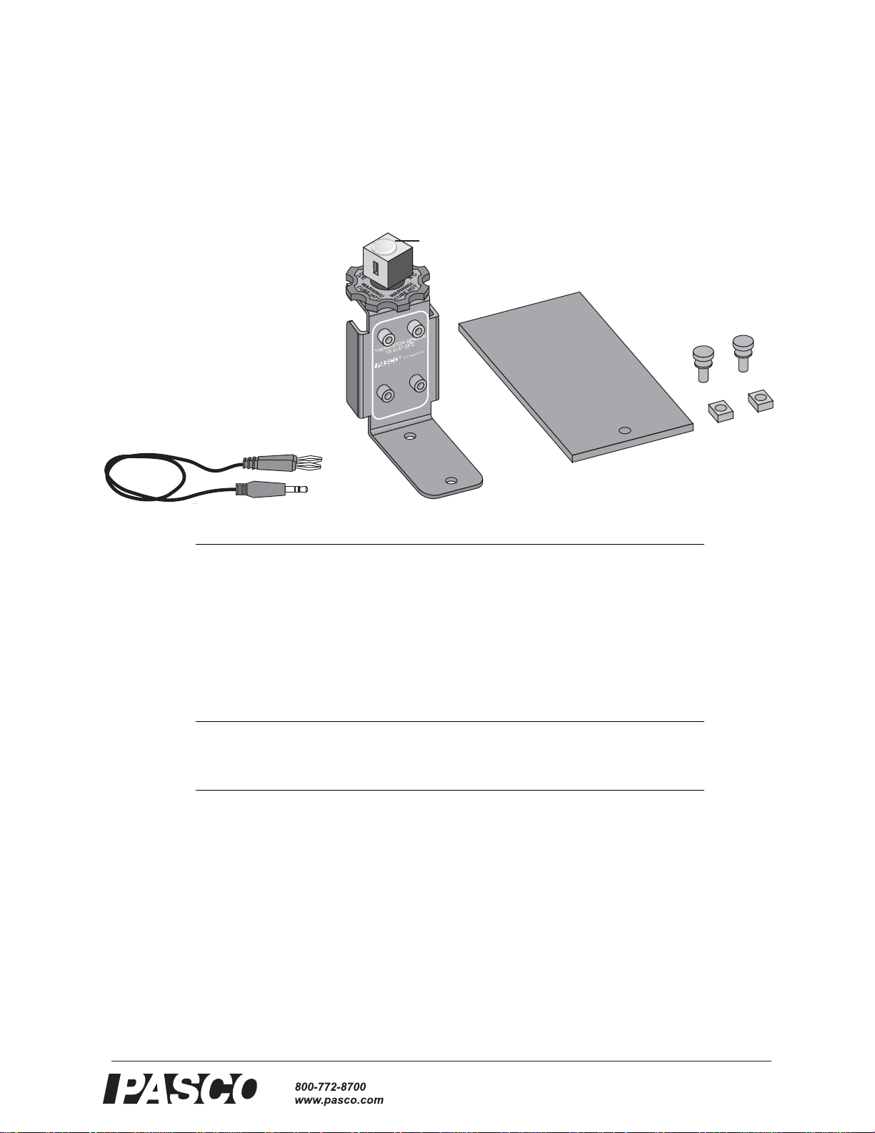
Included Equipment Part Number
1. Thermal Cavity Assembly TD-8580
2. Cavity Plug 699-122
3. Thermistor Cable PS-2515
4. Base ME-9205
5. Thumbscrews (qty. 2) 617-015
6. Square Nuts (qty. 2) 614-054
7. CD-ROM: Experiment Configuration
Files for DataStudio 576-09345
Required Equipment
Power Supply, 10 V, 1 A CI-6552A, PI-9877, SE- 9720a, SF-9584A, or similar
10 kΩ Thermistor-type Temperature Sensor
or
Resistance Meter
1
See “Suggested Experiments” starting on page 3 for more information about the recommended
equipment and additional equipment required for the experiments described in this manual.
1
CI-6527A, PS-2125, or similar
SE-9786A
4
4
Introduction
The TD-8580A Thermal Cavity can be used in studies of thermal radiation, the Stefan-Boltzmann law, and
reflection and emission of light from different surfaces. The rotatable aluminum cube has a cavity and four different surface finishes: black, white, polished, and matte.
When powered by a stand-alone power supply or a Power Amplifier connected to a ScienceWorkshop interface,
the built-in heating element can raise the temperature of the cube to 100 °C. A thermistor embedded in the cube
allows the temperature to be measured with a PASPORT Temperature Sensor, a ScienceWorkshop Thermistor
Sensor, or a resistance meter.
®
Page 2
Thermal Cavity Equipment Setup
With an Infrared Sensor students can examine IR light emission from each of the
cube's surfaces. The addition of a Light Sensor, Rotary Motion Sensor, Aperture
Bracket, and Linear Translator allows students to scan the cavity and generate intensity versus position graphs for visible and infrared light.
The apparatus can be mounted on the included rectangular base or on a PASCO Basic
Optics Bench.
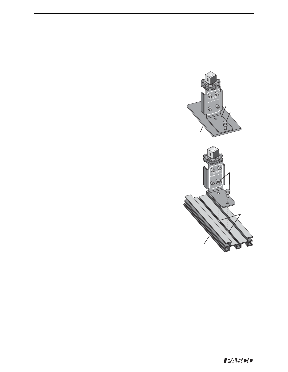
Equipment Setup
Mounting on Included Base
1. Place the apparatus upright with the chassis (horizontal support piece)
on the base.
2. Align the outer hole in the chassis with the tapped hole in the base.
3. Insert a thumbscrew through the hole in the chassis and thread it into
the base.
Mounting on an Optics Bench
Mount the apparatus on a Basic Optic Bench for use with a Linear Translator, Aperture Bracket, and other optics equipment.
1. Slide both nuts into the center slot of the optics bench.
2. Align the holes on the chassis of the Thermal Cavity apparatus with
the nuts.
3. Insert the thumbscrews through the holes in the chassis and thread
them loosely into the nuts.
4. Move the apparatus to the desired position on the optics bench.
5. Tighten the thumbscrews.
Base
580
-8
TD
AL C
M
ER
H
T
INPUT POWER
(10 VOLT MAX)
TD-8580A
THERMAL CAVITY
INPUT P
(10 V
A
ITY
AV
R
E
OW
AX)
OLT M
Chassis
Thumbscrew
Thumbscrews
Nuts
Thermistor Sensor Connection
Use the included cable to connect the white pair of jacks labeled
“THERMISTOR SENSOR” to a ScienceWorkshop Thermistor Sensor, a PASPORT
Temperature Sensor, or the temperature port of the Xplorer GLX interface.
You can also use a stand-alone resistance meter or multimeter to read the temperature.
Measure the resistance between the white jacks and use the conversion formula on
page 7 to calculate the temperature.
Power Supply Connection
The Thermal Cavity requires a power supply capable of 10 V and 1 A.
1. Use two banana patch cords to connect the power supply to the red pair of jacks
labeled “INPUT POWER.”
2. Set the voltage as high as 10 V. The cube will reach 100 °C in about 30 minutes.
2
Optics Bench
IMPORTANT: Do not
apply voltage to the white
thermistor jacks.
®
Page 3
Model No. TD-8580A Safety
Safety
CAUTION: The cube can reach 100 °C (212 °F). Do not touch the cube while
the apparatus is in use. Allow the apparatus to cool completely after use before
handling. Do not apply more than 10 V to the apparatus. Always monitor the temperature when the apparatus is in use. Do not allow the cube to exceed 100 °C. This
apparatus is intended for use by students only under instructor supervision.
Suggested Experiments
The configuration files called for in these activities can be found on the included
CD-ROM. There are three folders, each containing different versions of the files.
Refer to the table below to find the appropriate files for your equipment.
Equipment Folder containing configuration files
PASPORT PASPORT
ScienceWorkshop (without Power Amplifier) ScienceWorkshop
ScienceWorkshop with Power Amplifier SW with Power Amp
1. Infrared Light Intensity versus Temperature
In this experiment you will measure the IR intensity emitted by the cube as its temperature increases.
Required Equipment
Thermal Cavity TD-8580A
For use with PASPORT
Infrared Sensor PS-2148
Temperature Sensor PS-2125 or similar
PASPORT interface or interfaces
Power Supply, 10 V, 1 A PI-9877, SE- 9720a, SF-9584A, or similar
For use with ScienceWorkshop
Infrared Sensor CI-6628
Thermistor Sensor (10 kΩ) CI-6527A
ScienceWorkshop Interface See PASCO catalog or www.pasco.com
Power Amplifier
or
Power Supply, 10 V, 1 A
1
Any PASPORT temperature sensor compatible with thermistor temperature probes can be
used, including the Xplorer GLX’s built-in temperature port.
2
A multiple-port interface or combination of two single-port interfaces is required.
3
The Power Amplifier requires a ScienceWorkshop 750 or 700 interface.
3
2
See PASCO catalog or www.pasco.com
CI-6552A
PI-9877, SE- 9720a, SF-9584A, or similar
1
Setup
1. Mount the Thermal Cavity on the included base. Connect the Thermal Cavity to
the Thermistor Sensor and power supply (but don’t turn it on yet).
2. Connect both sensors to the interface (or interfaces).
1
3. Position the IR sensor on a stand or book so that its sensitive element is 2 cm
from the black surface of the cube.
®
1
If you are using a
ScienceWorkshop interface, connect the IR sensor to Channel A and the
Thermistor sensor to
Channel B; connect the
Power Amplifier (if used)
to Channel C; set the
gain of the IR Sensor
to 1.
3
Page 4

Thermal Cavity Suggested Experiments
4. Open the configuration file IR_vs_Temp.ds.
Procedure
Start with the cube below 40 °C.
1. Click Start.
2. Apply 10 V to the apparatus.
When the cube reaches 40 °C, data recording will automatically begin.
3. After the cube has reached 90 °C, click Stop. (If the cube reaches 100 °C, data
recording will automatically stop.)
4. Turn off power to the apparatus.
Analysis
1. According to your data, how is measured IR intensity related to cube temperature?
2. The Stefan-Boltzmann law states that a surface’s radiant intensity, I, is related to
its absolute temperature, T, by
I εσT
4
=
where ε is the emissivity of the surface, and σ is the Stefan-Boltzmann constant.
The measurement of I made by the IR sensor is proportional to the net power
exchange, P
, between the surface and the sensor. The net power is related to
net
the surface’s absolute temperature, T, and the sensor’s own absolute temperature,
T
, by
0
4
P
net
where k is a constant related to the geometry of the surface and the sensor.
εkσ T
4
T
–()=
0
2
Observe the graphs of I versus T and I versus T4. Does your data appear to
support this relationship?
3. Repeat the experiment with the polished and white surfaces of the cube. How do
the emissivities of the black, polished, and white surfaces compare?
5.670 × 10⁻⁸ W/m2·K
σ=
2
The PASPORT IR sensor makes a direct measurement of T
you can use in your analysis.
, which
0
4
4
®
Page 5
Model No. TD-8580A Suggested Experiments
2. Reflected Visible Light and Emitted Infrared Light
In this experiment you will measure the profile of visible light reflected by the cavity
side of the cube and compare it to the profile of infrared light emitted by it.
Required Equipment
Thermal Cavity TD-8580A
60 cm Optics Bench OS-8541 or part of OS-8515A
Linear Translator OS-8535
Aperture Bracket OS-8534
For use with PASPORT
Light Sensor PS-2106
Infrared Sensor PS-2148
Temperature Sensor PS-2125 or similar
Rotary Motion Sensor PS-2120
PASPORT Extension Cable
PASPORT interface or interfaces
Power Supply, 10 V, 1 A PI-9877, SE- 9720a, SF-9584A, or similar
For use with ScienceWorkshop
Light Sensor CI-6504A
Infrared Sensor CI-6628
Thermistor Sensor (10 kΩ) CI-6527A
Rotary Motion Sensor CI-6538
ScienceWorkshop Interface See PASCO catalog or www.pasco.com
Power Amplifier
or
Power Supply, 10 V, 1 A
1
Any PASPORT temperature sensor compatible with thermistor temperature probes can be
used, including the Xplorer GLX’s built-in temperature port.
2
Not required if the Light and IR sensors will be used with a USB Link.
3
A multiple-port interface or combination of three single-port interfaces is required.
4
The Power Amplifier requires a ScienceWorkshop 750 or 700 interface.
4
2
3
PS-2500
See PASCO catalog or www.pasco.com
CI-6552A
PI-9877, SE- 9720a, SF-9584A, or similar
1
Setup
1. Mount the Thermal Cavity on the Optics Bench.
Connect the thermistor sensor and power supply
(but don’t turn it on yet).
2. Mount the Linear Translator on the optics bench.
Assemble the Linear Translator, Aperture Bracket,
and Light Sensor (refer to the instructions accompanying the Linear Translator).
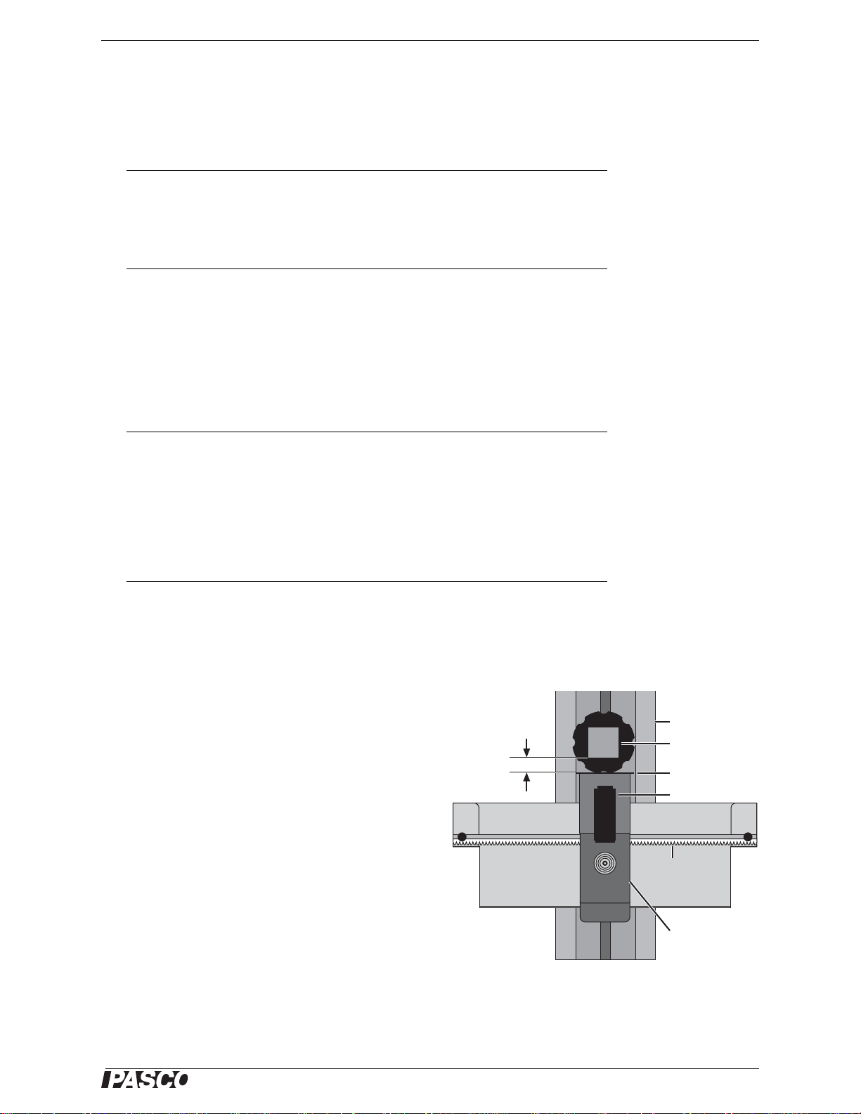
3. Arrange the apparatus so that the cavity side of the
cube is about 1.5 cm from the front of the Aperture
Bracket.
4. Turn the wheel on the Aperture Bracket to select
aperture #6.
5. Open the configuration file Reflected_and_Emitted_Light.ds.
®
1.5 cm
Optics Bench
Cube
Aperture Bracket
Light Sensor
Linear
Translator
Rotary Motion
Sensor
5
Page 6

Thermal Cavity Suggested Experiments
6. Connect the Light, Thermistor, and Rotary Motion sensors to the interface (or
interfaces).
3
Leave the IR Sensor unconnected for now.
7. In DataStudio, start data monitoring (open the Experiment menu and select Monitor Data). The measured cube temperature will appear in the digits display.
8. Turn on the power supply and set the voltage to 10 V. When the cube temperature
reaches about 80 °C, set the voltage to about 7 V. Allow the temperature to stabilize between 80 and 100 °C before proceding.
4
Procedure
1. Move the Light Sensor to one end of the Linear Translator.
2. Click Stop to stop data monitoring, then Click Start to start data recording.
3. Move the Light Sensor at a slow, steady pace across the Linear Translator to scan
the cavity side of the cube. Click Stop.
Observe the graph of Visible Light Intensity versus Position. If necessary, delete
the data
5
and repeat this step to obtain a satisfactory graph.
4. Remove the Light Sensor from the Aperture Bracket and replace it with the IR
Sensor. Connect the IR Sensor to the interface.
6
5. Move the IR Sensor to one end of the Linear Translator.
6. Click Start.
7. Move the IR Sensor at a slow, steady pace across the Linear Translator to scan
the cavity side of the cube. Click Stop.
3
If you are using a
ScienceWorkshop interface, refer to the
DataStudio configuration
file for sensor gain settings and channel asignments.
4
If you are using a Power
Amplifier, the power turns
on automatically whenever data is being monitored or recorded. The
temperature is thermostatically set for 80 °C.
Turn on data monitoring
between data-recording
runs to keep the cube
hot.
5
Open the Experiment
menu and select Delete
Last Run.
6
If you are using a Power
Amplifier and a
ScienceWorkshop interface, disconnect the
Light Sensor from Channel A and replace it with
the IR Sensor.
Observe the graph of IR Light Intensity versus Position. If necessary, delete the
data and repeat this step to obtain a satisfactory graph.
8. Turn off power to the Thermal Cavity.
Analysis
1. Compare the graphs of visible and IR light intensity. Which graph displays
reflected light and which displays emitted radiation?
2. When you look at the cavity, does it appear lighter or darker than the surrounding
cube surface? How is the appearance of the cavity represented in the graph of visible light intensity?
3. Allow the cube to cool to room temperature, then remove the cap from the top of
the cube. Does the inner surface of the cavity appear lighter or darker than outer
surface of the cube?
4. In the infrared region of the spectrum, was the cavity brighter or darker than the
cube surface?
5. Compare the emitted radiation of the cavity and the cube surface. Which source
of radiation has the higher emissivity?
6
®
Page 7
Model No. TD-8580A Sample Data
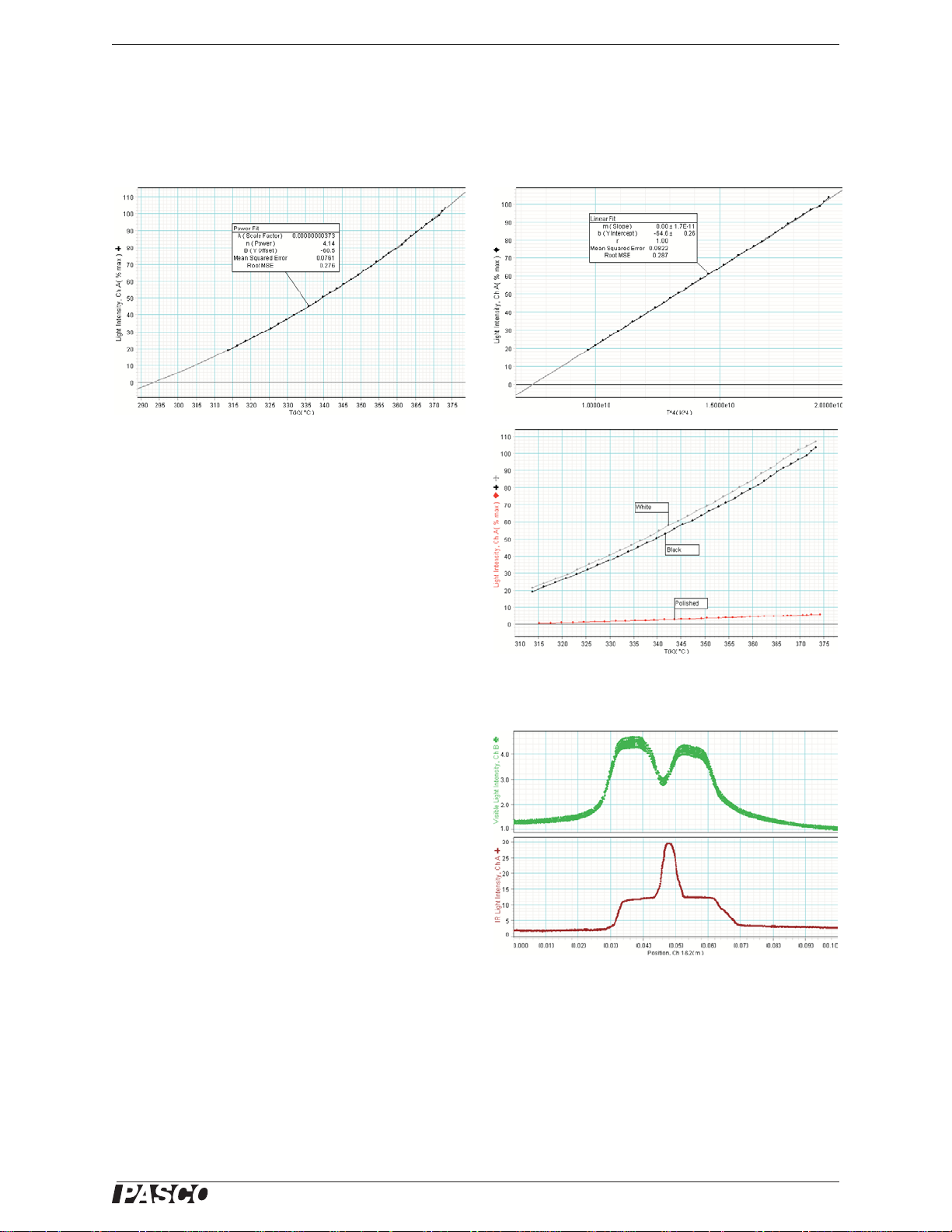
Sample Data
DataStudio files containing these data can be found on the included CD-ROM.
Infrared Light Intensity versus Temperature
The graphs above show I versus T (above left) and I
versus T
curve fit applied to I versus T is ; note
that the curve intersects the horizontal axis at
T 294 K 21° C==
the sensor.
The graphs of I versus T for the different surfaces of
the cube (right) show that the black and white surfaces
have similar emissivities in the IR region of the spectrum, and the emissivity of the polished surface is
much lower.
4
(above right) for the black surface. The
IAT
, the approximate temperature of
n
× B+=
Reflected Visible Light and Emitted Infrared Light
These graphs show visible light intensity versus position (top right) and IR light intensity versus position
(bottom right) at 92 °C. In the visible region of the
spectrum, the cavity is darker than the surrounding
cube surface; in the IR region the cavity is brighter.
Resistance to Temperature Conversion
To find the temperature (T) measured in kelvin based on the resistance (R) of the
embedded thermistor measured in kΩ, use the formula:
1
--- AB
T
®
R
------
ln⋅ C
10
2
R
------
ln
⋅ D
10
⋅++ +=
3
R
------
ln
10
7
Page 8

Thermal Cavity Specifications
where , , , and
A 3.35 10
D 8.37 10
×=
3–
×= B 2.56 104–×= C 2.38 106–×=
8–
.
Specifications
Power requirement 10 V, 1 A
Maximum input voltage 10 V
Heating resistor 10 Ω, 10 W max
Thermistor 10 kΩ at 25 °C
Maximum temperature 100 °C
Cube Aluminum, 3 × 3 × 3 cm
Technical Support
For assistance with any PASCO product, contact PASCO at:
Address: PASCO scientific
10101 Foothills Blvd.
Roseville, CA 95747-7100
Phone: 916-786-3800 (worldwide)
800-772-8700 (U.S.)
Fax: (916) 786-3292
Web: www.pasco.com
Email: support@pasco.com
Limited Warranty
For a description of the product warranty, see the PASCO catalog.
Copyright
The PASCO scientific 012-09373B Thermal Cavity Instruction Manual is copyrighted with all rights reserved. Permission is granted to
non-profit educational institutions for reproduction of any part of this manual, providing the reproductions are used only in their laboratories and classrooms, and are not sold for profit. Reproduction under any other circumstances, without the written consent of PASC O
scientific, is prohibited.
Trademarks
PASCO, PASCO scientific, DataStudio, PASPORT, ScienceWorkshop, Xplorer, and Xplorer GLX are trademarks or registered trademarks of PASCO scientific, in the United States and/or in other countries. All other brands, products, or service names are or may be
trademarks or service marks of, and are used to identify, products or services of, their respective owners. For more information visit
www.pasco.com/legal.
8
®
 Loading...