

Page 1
Instruction Manual and
Experiment Guide for the
PASCO scientific
Model TD-8579A
012-07599C
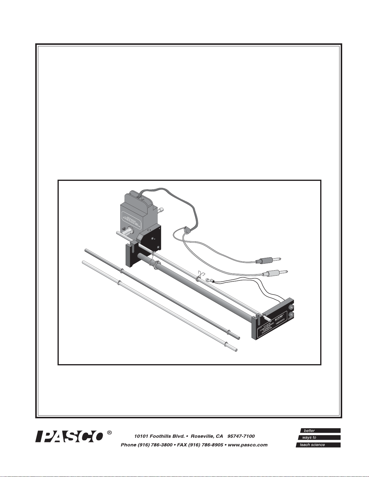
COMPUTER-BASED THERMAL
EXPANSION APPARATUS
© 2000 PASCO scientific
Page 2

012-07599C Computer-based Thermal Expansion Apparatus
Table of Contents
Section Page
Copyright, Warranty and Equipment Return....................................................i i
INTRODUCTION ..........................................................................................1
EQUIPMENT..................................................................................................2
APPARATUS SETUP....................................................................................3
EXPERIMENT SETUP: ................................................................................. 4
Calibration...............................................................................................4
Software Setup........................................................................................4
EXPERIMENT: Measuring the Coefficient of Linear Expansion for Copper,
Brass, and Aluminum:
Introduction ...................................................................................... 5-6
Procedure ......................................................................................... 5-6
Data and Calculations ..........................................................................7
Questions .............................................................................................7
SAMPLE DATA ............................................................................................. 8
TROUBLESHOOTING .................................................................................9
ADDITIONAL OR REPLACEMENT PARTS .......................................... 10
TECHNICAL SUPPORT .............................................................................11
i
Page 3

Computer-based Thermal Expansion Apparatus 012-07599C
Copyright, Warranty and Equipment Return
Please—Feel free to duplicate this manual
subject to the copyright restrictions below.
Copyright Notice
The PASCO scientific 012-07599 Computer-based
Thermal Expansion Apparatus manual is copyrighted and all rights reserved. However, permission is granted to non-profit educational institutions for reproduction of any part of the manual,
providing the reproductions are used only for their
laboratories and are not sold for profit. Reproduction under any other circumstances, without the
written consent of PASCO scientific, is prohibited.
Limited Warranty
PASCO scientific warrants the product to be free
from defects in materials and workmanship for a
period of one year from the date of shipment to the
customer. PASCO will repair or replace at its option
any part of the product which is deemed to be defective in material or workmanship. The warranty does
not cover damage to the product caused by abuse or
improper use. Determination of whether a product
failure is the result of a manufacturing defect or
improper use by the customer shall be made solely by
PASCO scientific. Responsibility for the return of
equipment for warranty repair belongs to the customer. Equipment must be properly packed to prevent
damage and shipped postage or freight prepaid.
(Damage caused by improper packing of the equipment for return shipment will not be covered by the
warranty.) Shipping costs for returning the equipment
after repair will be paid by PASCO scientific.
Equipment Return
Should the product have to be returned to PASCO
scientific for any reason, notify PASCO scientific by
letter, phone, or fax BEFORE returning the product.
Upon notification, the return authorization and
shipping instructions will be promptly issued.
➤ ➤
➤ NOTE: NO EQUIPMENT WILL BE
➤ ➤
ACCEPTED FOR RETURN WITHOUT AN
AUTHORIZATION FROM PASCO.
When returning equipment for repair, the units
must be packed properly. Carriers will not accept
responsibility for damage caused by improper
packing. To be certain the unit will not be damaged
in shipment, observe the following rules:
➀ The packing carton must be strong enough for
the item shipped.
➁ Make certain there are at least two inches of
packing material between any point on the apparatus and the inside walls of the carton.
➂ Make certain that the packing material cannot
shift in the box or become compressed, allowing
the instrument to come in contact with the packing
carton.
Address: PASCO scientific
10101 Foothills Blvd.
Roseville, CA 95747-7100
Phone: 1-800-772-8700 (outside the U.S.)
Or
(916) 786-3800
FAX: (916) 786-3292
email: techsupp@pasco.com
web: www.pasco.com
ii
Page 4

012-07599C Computer-based Thermal Expansion Apparatus
Introduction
Introduction
The PASCO Model TD-8579A Computer-based Thermal Expansion Apparatus provides easy and accurate
measurements for the coefficient of linear expansion for brass, copper, and aluminum. The PASCO
Model TD-8579A differs from the previous model TD-8578 in that it uses a Rotary Motion Sensor instead
of a dial gage for measuring length changes in the rod, a Thermistor Sensor instead of an ohmmeter, and
is compatible with a ScienceWorkshop® interface for recording sensor measurements in a computer.
The new PASCO CI-6527A Thermistor Sensor can be connected to the apparatus and a ScienceWorkshop
interface for viewing temperature readings inside DataStudio. With the new thermal expansion model,
students no longer have to convert resistance readings to temperature values using a conversion table.
DataStudio® provides immediate temperature feedback in either absolute temperature (degrees Kelvin),
degrees Celsius (C) or Fahrenheit (F). A setup diskette comes with the apparatus, which includes the predefined variables and equations for measuring temperature in degrees Celsius.
For the length measurement, the brass, copper, or aluminum tube is placed on the expansion base. The
length of the tube is measured at room temperature, then steam is passed through it. The expansion of the
length of the metal rod is measured with 0.006 mm resolution using the Rotary Motion Sensor. Temperatures are measured to within
the expansion of the metals at additional temperatures, hot or cold water can be passed through the metal
tubes.
+0.2 °C using a thermistor attached to the center of the tube. To investigate
Complete step-by-step instructions and a data sheet for results are provided in this manual.
Temperature Measurement with the Thermistor and Thermistor Sensor
A thermistor's resistance varies reliably with temperature. Typically, as the temperature of a metal rod
increases, the resistance decreases proportionally until the temperature equilibrates. Although the relationship between temperature and resistance is not linear, a linear approximation can be accurately used to
interpolate between table data points with an accuracy of approximately +0.2 0C.
The 10 kΩ thermistor used to measure the rod's temperature is embedded in the thermistor lug. Once
thermal equilibrium has been reached, the heat is highly uniform along the length of the rod. The foam
insulator is used to inhibit heat loss through the thermistor lug so the lug temperature closely follows the
rod's temperature. The insulator does not have any appreciable effect on the local temperature of the rod
itself.
Using the PASCO Thermistor Sensor with a ScienceWorkshop interface, the resistance is measured and
directly converted to a temperature measurement, which displays in DataStudio.
®
1
Page 5
Computer-based Thermal Expansion Apparatus 012-07599C
Equipment
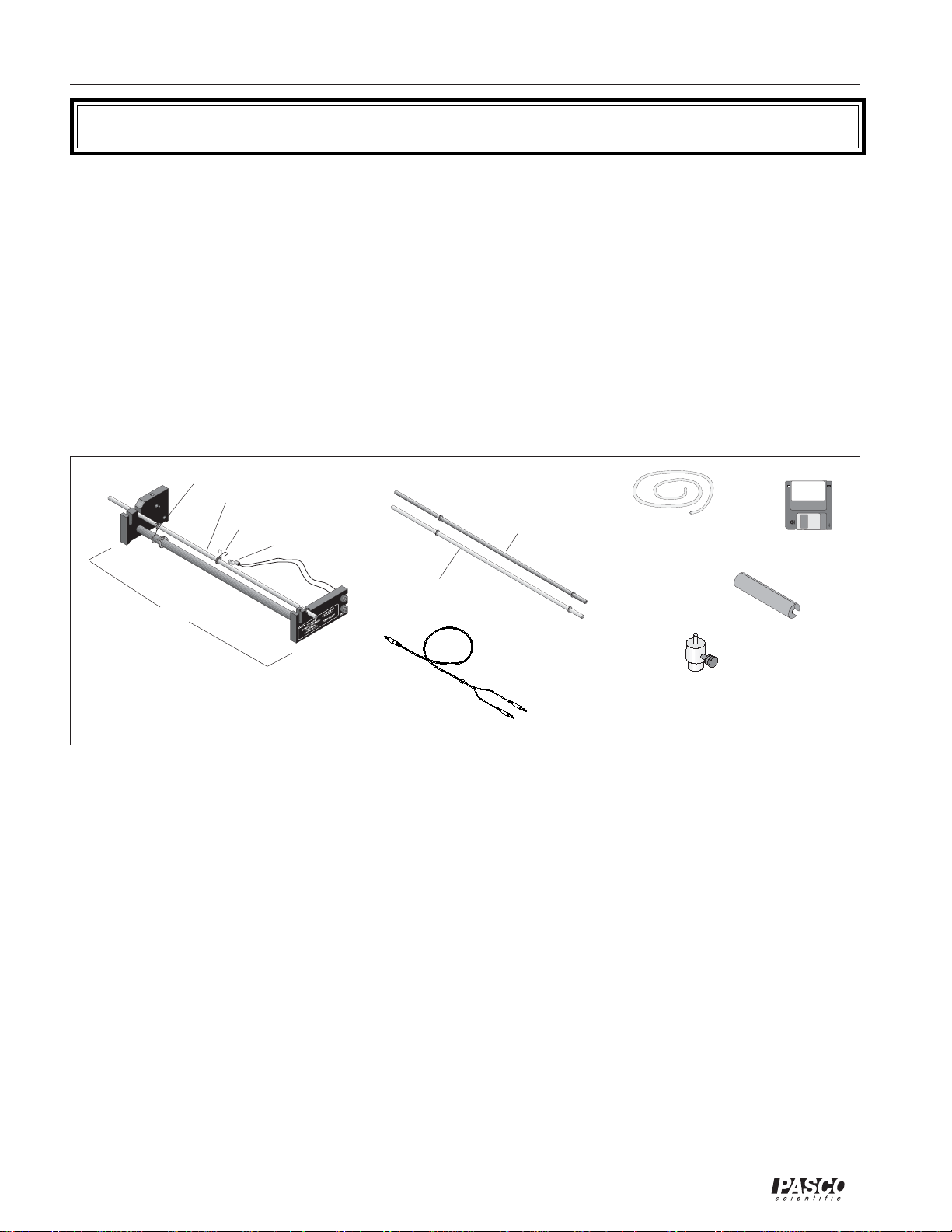
Equipment Included:
The TD-8579A Computer-based Thermal Expansion Apparatus includes:
• A 40-cm long expansion base with 10 kΩ thermistor
• 3 metal rods — brass, copper (99.5% Cu, 0.5% Te), and aluminum (98.9% Al, 0.7% Mg, 0.4%
Si): 6.4 mm outside diameter
• 1 foam insulator to avoid heat loss at the thermistor connection point
• Thermoplastic elastometer tubing with 6.4mm I.D.
• A 3.5 in. experiment setup diskette
• 1 pinion (6:1 ratio of disk radius to pin radius) for the Rotary Motion Sensor, Model CI-6538
• 1 stereo-to-dual banana plug cable for connecting a Thermistor Sensor (CI-5627A)
spring clip
aluminum rod
spring clamp
thermistor
brass rod
Expansion base
Thermal Expansion Apparatus (TD-8579A)
Stereo-to-dual banana plug cable for
connecting Thermistor Sensor (CI-6527A)
copper rod
copper and
brass rod
plastic tubing
6:1 ratio pinion for
a Rotary Motion
Sensor
Additional Equipment Required
In addition to the TD-8579A Thermal Expansion Apparatus, you need the following
items to perform the experiment, which is described on pages 5-6 of this manual:
• ScienceWorkshop Interface (500, 700 or 750)
• DataStudio®, version 1.5.2 or later
• PASCO Thermistor Sensor, Model No. CI-6527A
SETUP
013-07638
setup
diskette
foam wrap
• PASCO Rotary Motion Sensor, Model No. CI-6538
• A source of steam or hot water, such as the PASCO Model TD-8556A Steam
Generator
• A metric measuring tape or ruler
• A tube clamp to block off one side of the tubing from the Steam Generator
• A container to catch the water as it drains out of the metal rod
• Optional: If additional data points are desired, you will also need a source of
hot or cold water.
2
®
Page 6

012-07599C Computer-based Thermal Expansion Apparatus
Apparatus Setup
1. Attach the Rotary Motion Sensor (RMS) to
the large end block on the apparatus. Use
the black thumb screws to attach the RMS to
the holes in the larger of the black end blocks
(See Figure 1). Place the pinion onto the shaft
of the RMS and rotate clockwise to tighten.
pinion
shaft
end block
Figure 1: Mounting
the Rotary Motion
Sensor to the end block
of the Apparatus
Rotary Motion
Sensor
2. Align and anchor the copper rod in the expan-
sion base (Figure 2). The stainless steel ring on
the rod fits into the groove on the labeled mounting block, and the metal rod lies over and presses
against the pin on the Rotary Motion Sensor.
Hook the spring clip (on the support rod) over the
top metal rod and to the left side of the grip ring.
(Note: This anchors the rod and establishes the
zero position).
rotary motion
sensor pin
retaining ring
lug underneath the capture spring to attach the
thermistor lug beneath the clamp.
thermistor
capture
spring
Figure 3: Placing the Thermistor lug (with thermistor)
on the metal rod.
thermal rod
4. Plug the Sensors into the Interface. Insert the
DIN connector of the Thermistor Sensor into an
analog channel in the ScienceWorkshop interface. Attach the stereo plug of the Thermistor
Sensor cable into the 10 kΩ jack on the Thermistor Sensor. Insert the banana plugs for the
Rotary Motion Sensor into digital channels 1 and
2 (yellow=channel 1, black=channel 2) on the
ScienceWorkshop interface.
interface
cables to the Rotary
Motion Sensor
grip ring
spring clip
Detail A
Figure 2: Aligning and anchoring the metal rod in the
expansion base.
(see Detail A)
3. Attach the Thermistor lug beneath the spring
clamp on the metal rod. With one hand, place
the Thermistor lug over the top of the metal rod,
such that the concave side fits snugly over the
rod (Figure 3). Align the lug with the axis of the
rod, so that there is maximum contact between
the lug and the rod. With your other hand, press
the ends of the spring clamp together. Slide the
®
C
Thermistor
Sensor
Figure 4: Plugging the Thermistor and Rotary Motion
Sensors into the ScienceWorkshop Interface
3.5 Stereo Plug
5. Attach the Rotary Motion Sensor leads to
the apparatus. Insert the red and black
banana plugs into the jacks on the endblock
(the one with the Thermistor label).
Insert the red and
black banana
plugs here.
Figure 5: Attaching the banana plugs from the Thermistor Sensor to the end block of the apparatus
3
Page 7

Computer-based Thermal Expansion Apparatus 012-07599C
Experiment Setup
Calibration
The Thermistor Sensor and Rotary Motion Sensor are both factory-calibrated and do not require additional
calibration. However, if you wish to calibrate the Thermistor Sensor, you may do so. For calibration instruc-
tions, see the DataStudio (version 1.5.2 or later) online help.
Software Setup
Use the provided Thermal Expansion Setup diskette for setting up your experiment in DataStudio (v. 1.5.2 or
later). The Thermal Expansion Setup diskette includes the necessary sensor designation, pre-defined variables,
equations, etc., that you will need to run the experiment with the PASCO Thermal Expansion Apparatus (the
experiment on pages 5 to 6 of this manual).
Note: You must have DataStudio version 1.5.2 or later to run the setup diskette. PASCO provides a setup
diskette for either MacIntosh or Windows operating systems.
1) Insert the Thermal Expansion Setup diskette into your disk drive and open DataStudio. The Experiment
Setup window opens and shows the Rotary Motion Sensor icon and Thermistor Sensor icons. If your sensors
are connected to the thermal apparatus and ScienceWorkshop interface, and you have a heat source running
through the metal rod, you are ready to begin collecting data.
The following paragraphs describe the setup information contained in the setup diskette.
Sample Rate: The default sample rate for both the Rotary Motion and Thermistor Sensors is 5 Hertz
(Hz). If you want to change the sample rate, click on the sensor icon in the Experiment Setup window.
In the Sensor Properties dialog, use the plus and minus buttons to increase or decrease the sample rate.
Measurement units: The setup will give you temperature readings in degrees Celsius. If you also want to
view resistance measurements, go to the Experiment Setup window and doubleclick on the Thermistor
Sensor icon. In the Sensor Properties dialog, click on the Measurement tab and click to place a check in
the Resistance box.
Equation Setup: To view the pre-defined equations for temperature, position, etc., double click on the
appropriate Calculator icon in the Data List. The setup diskette includes the following equations:
Delta T = max(x) - min (x) (deg C), where delta T represents the change in temperature, max (x)
represents the maximum temperature achieved and min(x) represents the temperature at the initial start
time.
Position = x*radius (mm), where position is the linear position of the rod, x is the angular position in
radians, of the Rotary Motion Sensor, and the rotary pin radius is 1.327 mm.
Delta X = max(x) - min(x), where max(x) represents the longest position attained and min(x) represents
the initial position of the rod. The initial position is always zero.
Note: The position is calculated from the rotational change of the Rotary Motion Sensor pin. As the rod
expands, it pushes against the pin and causes the pin to rotate. From the radius of the pin and the amount of
angular rotation relative to the pin's zero position, the Rotary Motion Sensor determines the linear change in
length (L) for the rod.
4
®
Page 8

012-07599C Computer-based Thermal Expansion Apparatus
Experiment: Measuring the Coefficient of Linear
Expansion for Copper, Brass, and Aluminum
Introduction
Most materials expand when heated through a temperature range that does not produce a change in phase. The added heat increases the average amplitude of vibration
of the atoms in the material, which increases the average separation between the
atoms.
Suppose an object of length L undergoes a temperature change of magnitude ∆T. If
∆T is reasonably small, the change in length, ∆L, is generally proportional to L and
∆T. Stated mathematically:
∆L = αL ∆T;
where α is called the coefficient of linear expansion for the material.
Materials that are not isotropic, such as an asymmetric crystal for example, α can have
a different value depending on the axis along which the expansion is measured. The
coefficient (α) can also vary somewhat with temperature. Therefore, the degree of
expansion depends not only on the magnitude of the temperature change, but also on
the absolute temperature.
In this experiment, you will measure α for copper, aluminum, and brass. These
metals are isotropic, so it is necessary to measure α along only one dimension. Also,
within the limits of this experiment, α does not vary with temperature.
Procedure
rotary motion sensor
retaining pin
L = length
Figure 1: Measuring Tube Length
spring clamp
foam
Figure 2: Insulating the rod
1. With a measuring tape or
metric ruler, measure L, the
length of the aluminum rod,
at room temperature. Measure from the center of the
stainless steel ring (in the
groove of the small end
block), to the center of the
rotary pin at the other end
(see Figure 1). Record your
results in Table 1 in the Data
and Calculations section.
2. Insulate the rod and thermistor with
a slitted, tubular foam wrap. Slide
the foam wrap from underneath the
rod until the foam covers the
circumference of the rod. The
spring clamp should jut out from the
top of the foam slit (See Figure 2).
rotary
pin
®
5
Page 9

Computer-based Thermal Expansion Apparatus 012-07599C
Experiment (Continued)
3. Cut and place the plastic tubing over both
ports on top of the lid covering the Steam
Generator (See Figure 3). [Note: Cut the tubing
enough to allow it to reach the rod on the
apparatus, but keep the tubing as short as
possible, to prevent kinks and maximize rapid
heat transfer.] Plug one end off with a plastic
tube clamp. Connect the plastic tubing on the
other port to one end of the metal rod (the
labeled end block, away from the Rotary
Motion Sensor).
tube
clamp
Rotary
Motion
Sensor
STEAM
scientific
GENERATOR
MODEL TD-8556A
5
4
3
2
1
LOW HIGH
CAUTION: DO NOT IMMERSE IN WATER!
LOW WATER
115 VAC 5A
ON
6
220 VAC 2.5A
7
8
117VAC
OFF
4. In DataStudio, load the provided setup
diskette. (For more information on software
setup, see page 4).
5. Fill the Steam Generator half to threequarters full with water. Plug the Steam
Generator into a three-receptacle outlet.
[Do not use another outlet. Please refer to
the Steam Generator instruction sheet (012-
04696) for appropriate safety precautions
and settings.]
6. Turn on the Steam Generator and wait for it
to warm up. When you first hear a gurgle
sound, (but before the steam travels through
the clear tubing), click the START button to
begin recording the temperature. Steam will
begin flowing through the rod shortly
thereafter. As steam begins to flow, watch
the temperature rise in the DataStudio Graph
display as the rod heats.
CAUTION: THE STEAM GENERATOR AND
METAL ROD WILL BE HOT. TO AVOID
BURNS, DO NOT TOUCH!
Figure 3: Connecting the tubing from the Steam
Generator to the Thermal Expansion Apparatus
Figure 4: Experiment Setup
Note: Have a styrofoam cup or other basin available
to capture the steam running off the rod (the end
closest to the Rotary Motion Sensor.
When the temperature reading stabilizes, record the temperature change (∆T) in Table 1. Also record
the expansion of the rod's length (∆L), as indicated by the position displacement (x in mm). [Note: If
you want to increase the precision of your measurements, click on the Calculator button. In the
Calculator dialog, click on Properties. Under Precision, enter the number to indicate the number of
decimal places to display.]
7. In DataStudio, save your activity file for the aluminum rod. Repeat the experiment for the copper and
brass rods.
6
®
Page 10

012-07599C Computer-based Thermal Expansion Apparatus
Data and Calculations
1. In DataStudio, from the Digits display, record the maximum length change (delta ∆L) and the
temperature change (∆T) for each rod. Record your results in Table 1.
2. Using the equation ∆L = αL ∆T, calculate α for copper, brass, and aluminum. Record your results
in Table 2.
TABLE 1: Data and Calculations
TABLE 2: Coefficient of Thermal Expansion
lairetaM
reppoC71
ssarB91
munimulA32
ααααα 01x(tneiciffeoc
lairetaM)mm(L
reppoC
ssarB
munimulA
6-
/∞∞∞∞∞ )C ααααα )latnemirepxe(
∆∆∆∆∆ )mm(L ∆∆∆∆∆ (T)C°
ecnereffidtnecreP
)%(
Questions
1. Look at the accepted values for the linear expansion coefficient for copper, brass, and aluminum
(Table 2). Compare these values with your experimental values. What is the percentage
difference in each case? Is your experimental error consistently high or low?
2. On the basis of your answers in question 1, speculate on the possible sources of error in your
experiment. How might you improve the accuracy of the experiment?
®
7
Page 11

Computer-based Thermal Expansion Apparatus 012-07599C
Sample Data
The following are examples of data obtained using DataStudio™, a ScienceWorkshop® 750
Interface and the TD-8556A Steam Generator. The data will vary according to experimental
conditions, setup modifications, temperature of the heat source, type of experiment, temperature
units (degrees K, F, or C), etc.
Within Datastudio, you can use the cursor to adjust the axes to fit your data inside the
Graph display. Other displays, such as the Digits or Table display, may be simultaneously
or later opened to view actual data values. You can use the Smart Tool to display the
coordinates for the values at room temperature and at the final temperature at equilibrum.
Note: The displays shown are in DataStudio version 1.5.2. DataStudio
displays are subject to future modifications with continuous upgrades.
The displays shown may not appear identical to those of later versions.
maximum
temperature
change
temperature at
equilibrium
maximum
expansion at
boiling point
Figure 7: Data obtained during thermal expansion with
the aluminum tube
Resistance to Temperature Conversion Chart
(10K
16460W 14 °C 12,490W 20 °C 9,574W 26 °C 7,404W 32 °C
W
Thermistor)
maximum
length
change
15710W 15 °C 11,940W 21 °C 9,166W 27 °C 7,098W 33 °C
15000W 16 °C 11,420W 22 °C 8,778W 28 °C 6,808W 34 °C
14320W 17 °C 10,920W 23 °C 8,408W 29 °C 6,532W 35 °C
13680W 18 °C 10,450W 24 °C 8,058W 30 °C 6,268W 36 °C
13070W 19 °C 10,000W 25 °C 7,722W 31 °C 6,016W 37 °C
Table 3: Resistance to Temperature Conversion Chart
(10 kΩ Thermistor)
8
®
Page 12

012-07599C Computer-based Thermal Expansion Apparatus
Troubleshooting
Problem: During the experiment, temperature measurements do not appear in an open DataStudio
display.
Solution(s): a) Ensure that all connections between the Thermistor lug and rod, and Thermistor Sensor
and ScienceWorkshop interface are tight. (See Apparatus Setup on page 3 for instructions).
b) In DataStudio, double click on the Thermistor icon. Click on the Measurement tab.
Verify that there is a check in the box next to the Temperature option. If not, click to place
a check inside this box. Click OK to save the changes.
Problem: The temperature (or resistance if displaying) measurements do not appear accurate.
Solution(s): a) Ensure that all connections between the Thermistor lug and rod, and Thermistor Sensor
and ScienceWorkshop interface are tight. In the setup file the Thermistor Sensor is lugged
into Channel B of the interface. (See Apparatus Setup on page 3 for instructions). b) Make
sure that you have used the appropriate temperature equation for the units desired. The
setup diskette includes the equation for temperature in degrees Celsius (C). To perform
measurements in degrees Kelvin or Fahrenheit, define your own equation using the Calculator in DataStudio. c) If you have a couple of resistors available, you can calibrate and/or
check the resistance measurement accuracy of the Thermistor Sensor using a voltmeter or
multimeter. See the DataStudio online help for calibration instructions. d) If steps a), b),
and c) fail to correct the problem, you may have a faulty Thermistor Sensor. Call PASCO's
Technical Support Department (see page 11 of this manual) to order a replacement sensor.
Only Thermistor Sensor model CI-6527A measures a 10 kΩ thermistor. Model CI-6527
only measures 100 kΩ thermistors.
Problem: I want to view resistance measurements, but they do not appear in the Graph display.
Solution(s): The setup diskette does not include the settings for showing resistance measurements. This is
to help eliminate student confusion about resistance and shift the focus to temperature and
thermal expansion. However, if you want your students to see resistance data during the
experiment, do the following: a) In DataStudio setup window, double click on the Thermistor icon. Click on the Measurement tab. Verify that the box next to the Resistance option
is checked. If not, click to place a check inside this box. Click OK to save your changes.
Then perform another experiment run.
Problem: In DataStudio, position (length) measurements do not display or appear inaccurate.
Solution(s): a) Check to ensure that you have properly inserted the cables for the Rotary Motion Sensor
into the ScienceWorkshop interface. If you have reversed your banana plug connections,
you may observe negative readings. Also check that you have correctly aligned the rod in
the expansion base of the Thermal Expansion Apparatus. (See page 3 for instructions). b)
Check the software settings for the Rotary Motion Sensor in DataStudio. If you did not use
the setup diskette provided for this experiment, go to the Experiment Setup window and
double click on the Rotary Motion Sensor icon. In the General tab, set the sample rate to 5
Hz or try another sample rate. Click on the Measurement tab. Verify that Angular Position
(Rad) is checked. Click on the Rotary Motion Sensor tab. Verify that the divisions per
rotation is 1440. c) If steps a and b fail to yield accurate measurements, you may have a
faulty Rotary Motion Sensor. Call PASCO's Technical Support department (see page 11 of
this manual) for a replacement sensor.
®
9
Page 13

Computer-based Thermal Expansion Apparatus 012-07599C
Additional or Replacement Parts
You can order any of the following parts from PASCO scientific. See the Technical
Support section of this manual (page 11) for telephone and address information.
Description Part No.
Aluminum tube 648-07139
Banana plug connectors 517-010
Brass tube 648-07140
Copper tube 648-07141
Expansion base 003-07600
Experiment setup diskette 013-07599
Foam wrap, 6" length 716-041
Rotary Motion Sensor CI-6538
Spring clamp 632-07090
Steam Generator TD-8556A
Support tube 648-07086
Thermal Expansion Apparatus TD-8579A
Thermistor, 10 kΩ 150-040
Thermistor Sensor CI-6527A
Thermoplastic elastomer tubing with 6.4 I.D. 640-018
10
®
Page 14

012-07599C Computer-based Thermal Expansion Apparatus
Technical Support
Feedback
If you have any comments about the product or
manual, please let us know. If you have any suggestions on alternate experiments or find a problem in the
manual, please tell us. PASCO appreciates any
customer feedback. Your input helps us evaluate
and improve our product.
To Reach PASCO
For technical support, call us at 1-800-772-8700
(toll-free within the U.S.) or (916) 786-3800.
Fax: (916) 786-3292
E-mail: techsupp@pasco.com
Web: www.pasco.com
Contacting Technical Support
Before you call the PASCO Technical Support staff, it
would be helpful to prepare the following information:
➤ If your problem is with the PASCO apparatus, note:
- Title and model number (usually listed on the
label);
- Approximate age of apparatus;
- A detailed description of the problem/sequence of
events (in case you can’t call PASCO right away,
you won’t lose valuable data);
- If possible, have the apparatus within reach when
calling to facilitate description of individual parts.
➤ If your problem relates to the instruction manual,
note:
- Part number and revision (listed by month and
year on the front cover);
- Have the manual at hand to discuss your
questions.
®
11
 Loading...