

Page 1
Includes
Teacher's Notes
and
Typical
Experiment Results
Instruction Manual and
Experiment Guide for
012-03349D
5/94
the PASCO scientific
Model TD-8561
THERMAL CONDUCTIVITY
APPARATUS
© 1987 PASCO scientific $5.00
Page 2

Page 3

012-03349D Thermal Conductivity Apparatus
T able of Contents
Section.............................................................................................................. Page
Copyright, Warranty and Equipment Return..........................................................ii
Introduction ............................................................................................................ 1
Experiment:
Measuring Thermal Conductivity..................................................................... 3
Equipment Needed ..................................................................................... 3
Data and Calculations................................................................................. 4
Teacher’s Guide...................................................................................................... 5
Technical Support....................................................................... Inside Back Cover
i
Page 4
Thermal Conductivity Apparatus 012-03349D
Copyright, Warranty and Equipment Return
Please—Feel free to duplicate this manual
subject to the copyright restrictions below.
Equipment Return
Copyright Notice
The PASCO scientific Model TD-8561 Thermal
Conductivity Apparatus manual is copyrighted and all
rights reserved. However, permission is granted to
non-profit educational institutions for reproduction of
any part of this manual providing the reproductions
are used only for their laboratories and are not sold for
profit. Reproduction under any other circumstances,
without the written consent of PASCO scientific, is
prohibited.
Limited Warranty
PASCO scientific warrants this product to be free
from defects in materials and workmanship for a
period of one year from the date of shipment to the
customer. PASCO will repair or replace, at its option,
any part of the product which is deemed to be defective in material or workmanship. This warranty does
not cover damage to the product caused by abuse or
improper use. Determination of whether a product
failure is the result of a manufacturing defect or
improper use by the customer shall be made solely by
PASCO scientific. Responsibility for the return of
equipment for warranty repair belongs to the customer. Equipment must be properly packed to prevent
damage and shipped postage or freight prepaid.
(Damage caused by improper packing of the equipment for return shipment will not be covered by the
warranty.) Shipping costs for returning the equipment, after repair, will be paid by PASCO scientific.
Should the product have to be returned to PASCO
scientific for any reason, notify PASCO scientific by
letter, phone, or fax BEFORE returning the product.
Upon notification, the return authorization and
shipping instructions will be promptly issued.
ä
NOTE: NO EQUIPMENT WILL BE
ACCEPTED FOR RETURN WITHOUT AN
AUTHORIZATION FROM PASCO.
When returning equipment for repair, the units
must be packed properly. Carriers will not accept
responsibility for damage caused by improper
packing. To be certain the unit will not be
damaged in shipment, observe the following rules:
➀ The packing carton must be strong enough for the
item shipped.
➁ Make certain there are at least two inches of
packing material between any point on the
apparatus and the inside walls of the carton.
➂ Make certain that the packing material cannot shift
in the box or become compressed, allowing the
instrument come in contact with the packing
carton.
Address: PASCO scientific
10101 Foothills Blvd.
Roseville, CA 95747-7100
Phone: (916) 786-3800
FAX: (916) 786-3292
email: techsupp@pasco.com
web: www.pasco.com
ii
Page 5

012-03349D Thermal Conductivity Apparatus
Introduction
Thermal Conductivity Apparatus
Heat can be transferred from one point to another by three
common methods: conduction, convection and radiation.
Each method can be analyzed and each yields its own
specific mathematical relationship. The TD-8561 Thermal
Conductivity Apparatus allows one to investigate the rate
of thermal conduction through five common materials
used in building construction.
The equation giving the amount of heat conducted through
a material is:
∆Q = k A ∆T ∆t / h.
In this equation,
is the area through which conduction takes place,
temperature difference between the sides of the material,
∆t is the time during which the conduction occurred and h
is the thickness of the material. The remaining term, k, is
the thermal conductivity of a given material.
The units for k depend upon the units used to measure the
other quantities involved. Some sample conversions
between different possible sets of units are shown in Table
1.
Watt cm 1.338 x 10
cm2 °K
Watt m 1.338 x 10-54.818 x 10-20.5782 6.938
m2 °K
Watt in. 9.485 x 10
in.2 °R
Cal cm 5.600 x 10
cm2 sec °K
∆Q is the total heat energy conducted, A
∆T is the
Btu in. Btu in. Btu ft Btu in.
in.2 sec °R in.2 hr °Rft2 hr °Rft2 hr °R
-2
4.818 57.82 693.8
-4
3.414 40.97 491.7
-3
20.16 241.9 2.903 x 10
The technique for measuring thermal conductivity is
straightforward. A slab of the material to be tested is
clamped between a steam chamber, which maintains a
constant temperature of 100 °C, and a block of ice, which
maintains a constant temperature of 0°C. A fixed temperature differential of 100 °C is thereby established between
the surfaces of the material. The heat transferred is
measured by collecting the water from the melting ice. The
ice melts at a rate of 1 gram per 80 calories of heat flow
(the latent heat of melting for ice).
The thermal conductivity, k, is therefore measured using
the following equation:
k = (cal cm/cm
2
sec) =
(mass of melted ice) (80 cal/gm) (thickness of material)
(area of ice) (time during which ice melted) (temp.
differential)
where distances are measured in centimeters, masses in
grams, and time in seconds.
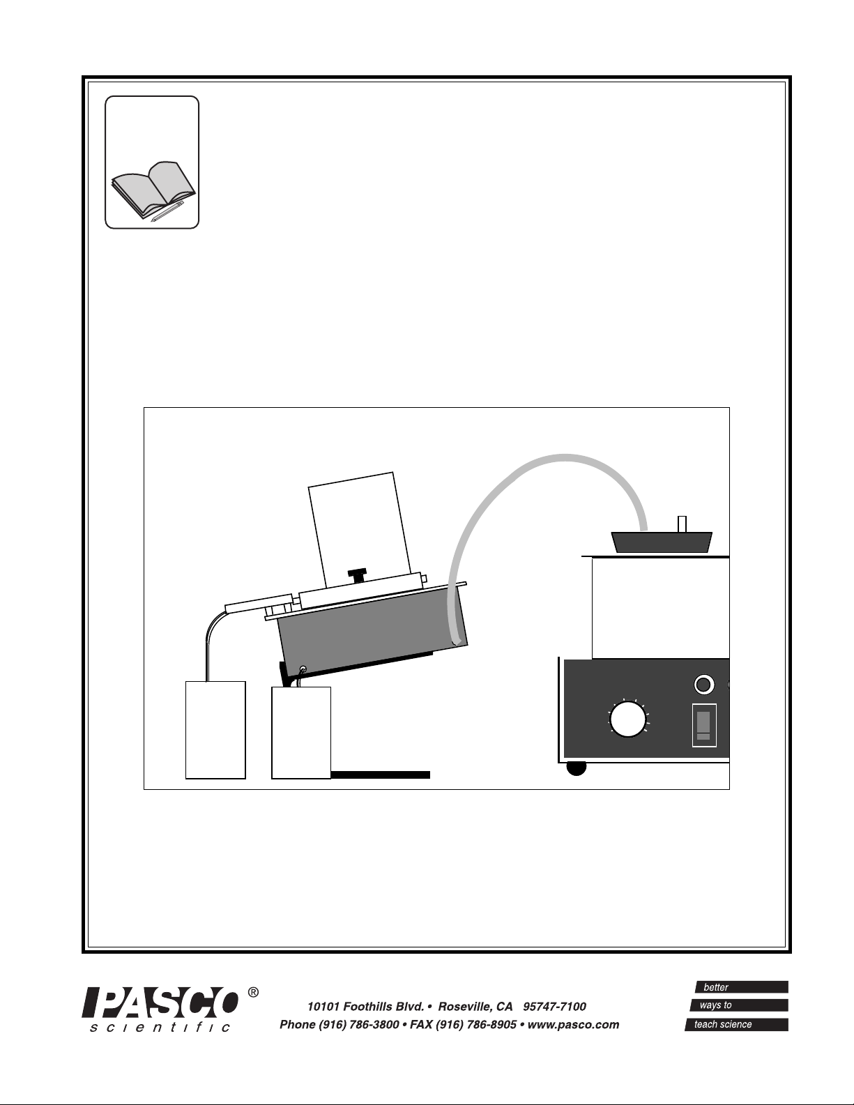
The Thermal Conductivity Apparatus includes the following equipment (see Figure 1):
• Base
• Steam chamber with hardware for mounting sample
• Ice mold with cover (Part # 648-03427)
• Materials to test: Glass, wood, lexan, masonite, and
sheet rock (The wood, masonite, and sheet rock are
covered with aluminum foil for waterproofing.)
3
Table 1
The importance of k lies in whether one wishes to conduct
heat well (good conductor) or poorly (good insulator).
Therefore, the relative size of k is of importance to
designers and builders, and should be of importance to
home owners.
Note further that choosing a material with a small value
for k does not guarantee a well-insulated structure. The
amount of heat conducted out in winter (and therefore
needing to be replaced) depends also upon three other
factors: area, thickness and temperature difference. The
same holds true for heat conducted in during the summer.
The equation for determining k is:
k =
∆Q h / A ∆T ∆t = _____
Steam
chamber
with hardware
for
mounting
sample
Figure 1 Equipment Included with the Thermal
Conductivity Apparatus
1
Base
Materials to test
(Glass, wood,
lexan, masonite,
sheet rock)
(Part# 648-03427)
Ice mold
Page 6

Thermal Conductivity Apparatus 012-03349D
Notes
2
Page 7

012-03349D Thermal Conductivity Apparatus
Experiment: Measuring Thermal Conductivity
EQUIPMENT NEEDED:
— Steam generator that will deliver approxi-
mately 10 grams/minute (e.g., PASCO’s
Model TD-8556 Steam Generator)
— Freezer
— Container to collect melted ice (a paper
cup is fine)
— Gram balance to weigh collected water
(you could collect the water in a graduated
flask, but your results will be less accurate)
— Container to collect condensed steam
— Grease such as petroleum jelly
("Vaseline")
Measuring Thermal Conductivity
➀ Fill the ice mold with water and freeze it. Do not freeze water with lid on jar. (A few drops of
a non-sudsing detergent in the water before freezing will help the water to flow more freely
as it melts and will not significantly effect the results.)
➁ Run jar under warm water to loosen the ice in the mold.
➤ NOTE: Do not attempt to “pry” the ice out of the mold.
➂ Measure and record h, the thickness of the sample material.
Mount the sample material onto the steam chamber as shown in Figure 2.
➃
➤ NOTE: Take care that the sample material is flush against the water channel, so water will
not leak, then tighten the thumbscrews. A bit of grease between the channel and the sample
will help create a good seal.
➄ Measure the diameter of the ice block. Record this value as d
. Place the ice on top of the
1
sample as shown in Figure 2. Do not remove the ice but make sure that the ice can move
freely in the mold. Just place the open end of the mold against the sample, and let the ice
slide out as the experiment proceeds.
(Top View)
Water channel
Container for collecting
melted ice
Ice in Mold with bare ice
against material sample
Clamps
Material
sample
Container for collecting
condensed steam
Figure 2 Experimental Setup
Steam
Generator
3
Page 8

Thermal Conductivity Apparatus 012-03349D
Let the ice sit for several minutes so it begins to melt and comes in full contact with the sample. (Don't
➅
begin taking data before the ice begins to melt, because it may be at a lower temperature than 0 °C.)
Obtain data for determining the ambient melting rate of the ice, as follows:
➆
a. Determine the mass of a small container used for collecting the melted ice and record it.
b. Collect the melting ice in the container for a measured time t
(approximately 10 minutes).
a
c. Determine the mass of the container plus water and record it.
d. Subtract your first measured mass from your second to determine m
, the mass of the melted ice.
wa
➇ Run steam into the steam chamber. Let the steam run for several minutes until temperatures stablize so
that the heat flow is steady. (Place a container under the drain spout of the steam chamber to collect the
water that escapes from the chamber.)
➈ Empty the cup used for collecting the melted ice. Repeat step 7, but this time with the steam running
into the steam chamber. As before, measure and record m
, the mass of the melted ice, and t, the time
w
during which the ice melted (5-10 minutes).
➉ Remeasure the diameter of the ice block and record the value as d
DATA AND CALCULATIONS
➀ Take the average of d
➁ Use your value of d
and d2 to determine d
1
to determine A, the area over which the heat flow between the ice and the steam
avg
, the average diameter of the ice during the experiment.
avg
chamber took place. (Assume that A is just the area of the ice in contact with the sample material.)
➂ Divide m
by ta and mw by t to determine Ra and R, the rates at which the ice melted before and after
wa
the steam was turned on.
Subtract R
➃
from R to determine R0, the rate at which the ice melted due to the temperature differential
a
only.
➄ Calculate k, the conductivity of the sample:
k (cal cm/cm
2
sec) = _________
∆T = Boiling point of water (100 °C at sea level) - 0°C.
Data and Calculations Table
hd1d
2
t
a
m
wa
tmwd
avg
.
2
ARaRR
0
(R0) (80 cal/gm) (h)
(A) (∆T);
4
Page 9

012-03349D Thermal Conductivity Apparatus
T eacher’s Guide
Experiment: Thermal Conductivity Apparatus
Notes on Procedure
➀ Expect 10-15% error under normal (student labora-
tory) operating conditions.
➁ Keep the ice as isolated from the surroundings as
possible. Our best results were obtained using a
PASCO styrofoam calorimeter cup as an ice mold;
however, this has the disadvantage of splitting the
cup when the water freezes. (Medium-sized
styrofoam cups also work very nicely.) Whatever
mold you use, leave it
on the ice during the experi-
ment.
Accepted Values
Substance cal•cm/cm2•sec•°C watt•m/m2•K
Masonite 1.13 x 10-
Wood (Pine) 206 - 3.3 x 10-
➂ Apply a dab of grease to the joint between the plate
and the water trough to prevent leakage. Vaseline
works well; it melts, but still seals the gap.
➃
A note about the aluminum covers on some
samples: This was found experimentally to have no
measurable effect on the conductivity of the
samples. We tested this using a glass plate which
we measured both with and without an aluminum
cover, and there was no statistically significant difference between multiple readings in both states.
4
4
0.047
0.11 - 0.14
®
Lexan 4.6 x 10-
Sheet Rock 10.3 x 10-
Glass 17.2 - 20.6 x 10-
4
4
4
0.19
0.43
0.72 - 0.86
Note
Values (with the exception of Lexan) from the Handbook of Chemistry and Physics, 46th Edition, published by
The Chemical Rubber Company. Value for Lexan is from a specifications sheet provided by the manufacturer.
Values for Masonite and for Sheet Rock will vary considerably.
5
Page 10

Thermal Conductivity Apparatus 012-03349D
Notes
6
Page 11

012-03349D Thermal Conductivity Apparatus
T echnical Support
Feed-Back
If you have any comments about this product or this
manual please let us know. If you have any suggestions on alternate experiments or find a problem in the
manual please tell us. PASCO appreciates any customer feed-back. Your input helps us evaluate and
improve our product.
To Reach PASCO
For Technical Support call us at 1-800-772-8700 (tollfree within the U.S.) or (916) 786-3800.
Contacting Technical Support
Before you call the PASCO Technical Support staff it
would be helpful to prepare the following information:
• If your problem is computer/software related, note:
Title and Revision Date of software.
Type of Computer (Make, Model, Speed).
Type of external Cables/Peripherals.
• If your problem is with the PASCO apparatus, note:
Title and Model number (usually listed on the label).
Approximate age of apparatus.
A detailed description of the problem/sequence of
events. (In case you can't call PASCO right away,
you won't lose valuable data.)
If possible, have the apparatus within reach when
calling. This makes descriptions of individual parts
much easier.
• If your problem relates to the instruction manual,
note:
Part number and Revision (listed by month and year
on the front cover).
Have the manual at hand to discuss your questions.
7
Page 12

 Loading...