

Page 1
Instruction Manual for
012-02141H
the PASCO scientific
Model SF-9216
Variable Output Air Supply
1/96
POWER
ON
OFF
SF-9216
AIR SUPPLY
2
1
6
AIR OUTPUT
3
4
5
© 1991 PASCO scientific $5.00
Page 2
Variable Output Air Supply 012-02141H
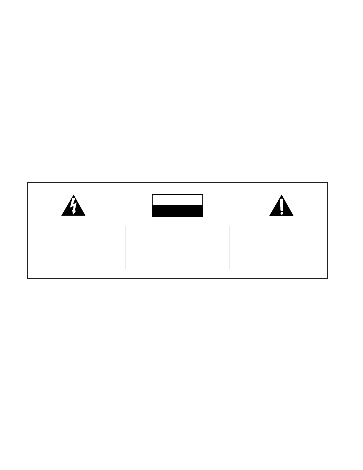
The lightning flash with arrowhead,
within an equilateral triangle, is intended
to alert the user of the presence of
uninsulated “dangerous voltage” within
the product’s enclosure that may be of
sufficient magnitude to constitute a risk
of electric shock to persons.
CAUTION
RISK OF ELECTRIC SHOCK
DO NOT OPEN
CAUTION:
TO PREVENT THE RISK OF
ELECTRIC SHOCK, DO NOT
REMOVE BACK COVER. NO USER
SERVICEABLE PARTS INSIDE.
REFER SERVICING TO QUALIFIED
SERVICE PERSONNEL.
The exclamation point within an equilateral triangle is intended to alert the
user of the presence of important
operating and maintenance (servicing) instructions in the literature accompanying the appliance.
®
Page 3

012-02141H Variable Output Air Supply
T able of Contents
Section..........................................................................................................Page
Copyright, Warranty, and Equipment Return..................................................ii
Introduction .....................................................................................................1
Operation .........................................................................................................1
Operating Two Air Tracks...............................................................................2
PCB Schematic ................................................................................................3
PCB Layout .....................................................................................................4
®
i
Page 4

Variable Output Air Supply 012-02141H
Copyright, Warranty and Equipment Return
Please—Feel free to duplicate this manual
subject to the copyright restrictions below.
Copyright Notice
The PASCO scientific Model SF-9216 Variable Output
Air Supply manual is copyrighted and all rights reserved.
However, permission is granted to non-profit educational
institutions for reproduction of any part of this manual
providing the reproductions are used only for their
laboratories and are not sold for profit. Reproduction
under any other circumstances, without the written
consent of PASCO scientific, is prohibited.
Limited Warranty
PASCO scientific warrants this product to be free from
defects in materials and workmanship for a period of one
year from the date of shipment to the customer. PASCO
will repair or replace, at its option, any part of the product
which is deemed to be defective in material or workmanship. This warranty does not cover damage to the product
caused by abuse or improper use. Determination of
whether a product failure is the result of a manufacturing
defect or improper use by the customer shall be made
solely by PASCO scientific. Responsibility for the return
of equipment for warranty repair belongs to the customer.
Equipment must be properly packed to prevent damage
and shipped postage or freight prepaid. (Damage caused
by improper packing of the equipment for return shipment will not be covered by the warranty.) Shipping
costs for returning the equipment, after repair, will be
paid by PASCO scientific.
Equipment Return
Should the product have to be returned to PASCO
scientific for any reason, notify PASCO scientific by
letter, phone, or fax BEFORE returning the product.
Upon notification, the return authorization and
shipping instructions will be promptly issued.
ä
NOTE: NO EQUIPMENT WILL BE
ACCEPTED FOR RETURN WITHOUT AN
AUTHORIZATION FROM PASCO.
When returning equipment for repair, the units
must be packed properly. Carriers will not accept
responsibility for damage caused by improper
packing. To be certain the unit will not be
damaged in shipment, observe the following rules:
➀ The packing carton must be strong enough for the
item shipped.
➁ Make certain there are at least two inches of
packing material between any point on the
apparatus and the inside walls of the carton.
➂ Make certain that the packing material cannot shift
in the box or become compressed, allowing the
instrument come in contact with the packing
carton.
Credits
This manual edited by: Dave Griffith
Address: PASCO scientific
10101 Foothills Blvd.
Roseville, CA 95747-7100
Phone: (916) 786-3800
FAX: (916) 786-3292
email: techsupp@pasco.com
web: www.pasco.com
ii
®
Page 5

012-02141H Variable Output Air Supply
SF-9216
AIR SUPPLY
5
4
3
2
1
6
AIR OUTPUT
POWER
ON
OFF
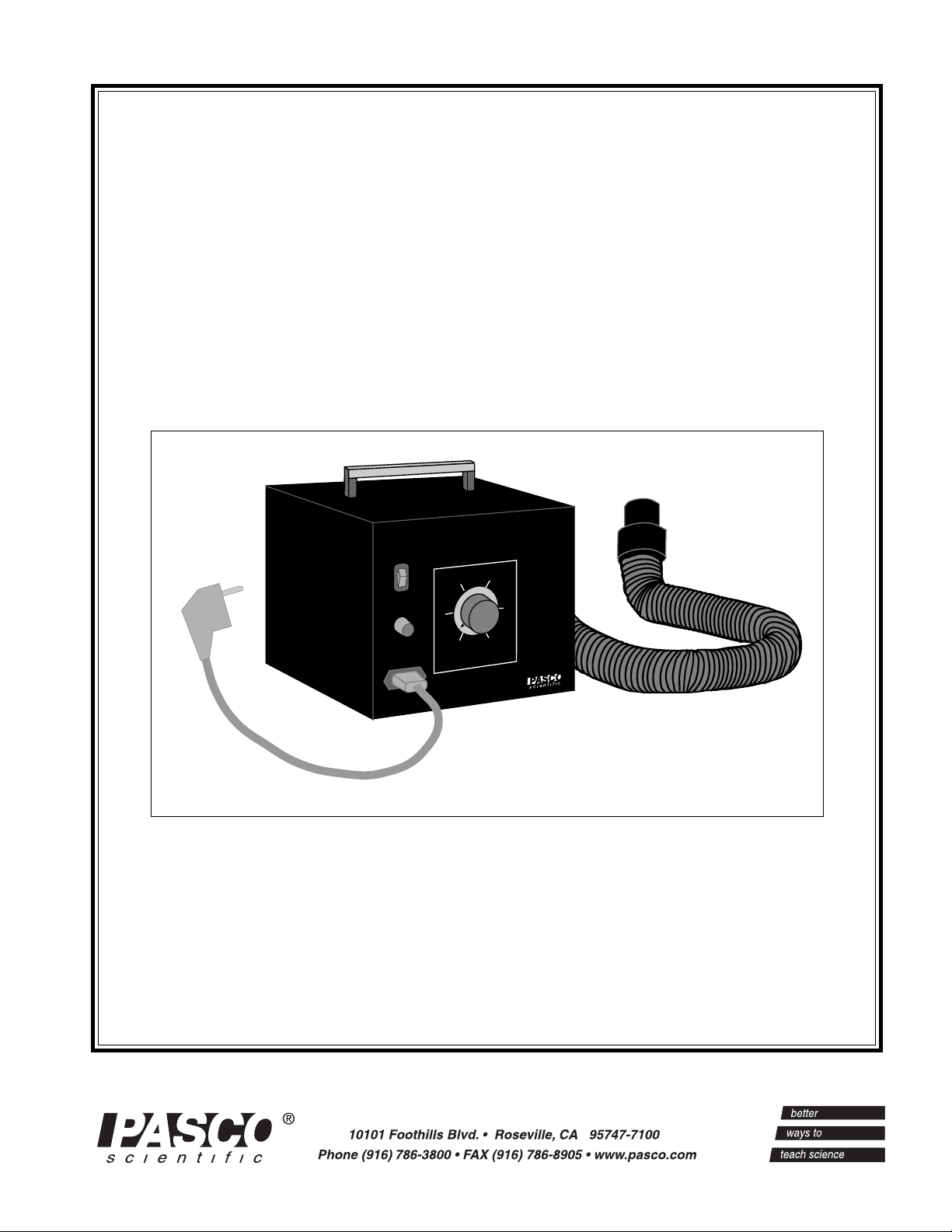
Introduction
The PASCO Air Supply is exceptionally quiet, and its
variable output lets you precisely match the air flow to the
experiment. (Too much air causes turbulence, resulting in
glider drift.)
A 2.0 meter hose is included. By adding the SF-9217
T-Adapter and Hose described below, the Air Supply can
be used to operate two PASCO SF-9214 Air Tracks at the
same time.
➤ NOTE: This Air Supply is for use with the
SF-9214 Precision Air Track. If used with a
different track, the total area of the air flow holes
must be ≥ 2.6 cm
2
(0.4 in2).
(220/240 VAC,
50 Hz shown)
Figure 1 SF-9216 Air Supply
Operation
Setting Up the Air Supply
Insert the short, thick-wall coupling on one end of the
hose into the hole in rear of the air supply. The other end
of the hose, with the longer, thin-wall coupling, fits into
the hole of the PASCO 2 meter Precision Air Track
(square cross section, aluminum color).
Connect the air supply to a wall socket (115 VAC, 60 Hz
or 220/240 VAC, 50 Hz). The respective line voltages are
marked on the rear panel. Turn the unit on with the
power switch.
Leave at least three inches of clearance around all sides of
the blower for air intake and cooling.
If you wish to connect the SF-9216 Air Supply to the
Daedalon 1.5 m Air Track (triangular cross section, black
color) it will be necessary to wrap one or two layers of
electrician’s tape around the air coupling on the track.
The hose from the Air Supply should now fit snugly over
the coupling.
®
Adjusting the Air Supply
The air flow from the Air Supply is easily adjusted by the
knob on the front panel. Once the air track is set up and
operating, adjust the air flow until the gliders just glide
freely on the track.
If the air flow is too low, the glider will touch the track
and lose energy.
A higher air flow may cause the gliders to move randomly in response to air turbulence around the surface of
the track.
➤ NOTE: The apparatus is calibrated at 220 VAC, 50
Hz and must be re-calibrated for 220 VAC, 60 Hz.
Please follow the instructions in the following section.
1
Page 6

Variable Output Air Supply 012-02141H
Adjusting the Motor Speed (Air Flow)
Turn the control knob fully COUNTER-clockwise. After
switching on the motor, slowly turn the control knob
CLOCKWISE. The motor should begin running when the
pointer on the control knob is near the “2” position. If it
does not, then follow this procedure:
➤CAUTION: When the case is opened, there will
be exposed high voltages. This unit should be
serviced or adjusted only by trained technicians.
➀ Remove the four screws which attach the control
panel to the main unit.
➁ On one end of the printed circuit board are two trim
potentiometers designated as TR1 and TR2 (See Figure 3).
Operating T wo Air Tracks
➂ Set TR1 and TR2 to their mid position and turn the
power switch to “ON”.
➃ Set the speed control knob (P1) fully counter-clock-
wise (“1”) and turn TR1 clockwise until the motor just
begins to turn smoothly.
➄ Set the speed control knob fully clockwise (“6”) and
adjust TR2 until the motor runs at maximum speed.
➅ Replace the control panel.
Fuse Replacement
The fuse is a dual-element delay type. Replace with the
following fuse ratings:
For the 110V version use a 5A/117V fuse.
For the 220V version use a 2.5A/250V fuse.
Operating Two Air Tracks
Two air tracks may be operated on a single Air Supply by
using the optional ‘T’ and hose, Model SF-9217. The ‘T’
is inserted into the Air Supply and one hose is connected
to one of the outlets. Naturally, both air tracks must be
connected to maintain air pressure.
Specifications
➀ When connected to the SF-9214 Precision Air Track
(382 holes @ 1 mm (0.038 in) diameter each, total
hole area 300 mm2 (0.433 in2), the volume and pressure is sufficient to lift a glider with a 200 g load (setting at 50% of full range).
➁ The input current at full speed is 2.2 Amps maximum.
➂ The sound output is typically 10 - 20 dB above ambi-
ent noise. The maximum sound output is low enough
to allow normal conversation to be heard when the
motor is on.
➃ The volume of air produced is 1.02 m
min) and the pressure is 867 Pascals (0.0867 N/cm2 or
0.122 lbs/in2) or 6.5 mm Hg at full speed.
3
/min (36 ft3/
➤ CAUTION:
For those using SF-9216 Air Supply with equipment other than the PASCO Model SF- 9214
Precision Student Air Track: This air supply is
designed for use with equipment for which the total
area of air flow is at least 2.6 cm2 (0.4 in2). (For air
tracks, this area is determined by multiplying the
number of air holes on the surface of the track by
the surface area per hole).
When used with equipment for which the air flow
orifice is less than this value, the rate of air flow is
insufficient to cool the air supply, and the supply
may overheat and be damaged.
You may remedy this problem either by hooking up
the air supply to additional equipment (to meet the
2.6 cm2 or 0.4 in2 requirement) or by bleeding the
air line at some point to increase the area of the
unrestricted air flow to an acceptable level.
®
2
Page 7

012-02141H Variable Output Air Supply
PCB Schematic
Figure 2
®
3
Page 8

Variable Output Air Supply 012-02141H
PCB Layout
Figure 3
4
®
Page 9

012-02141H Variable Output Air Supply
T echnical Support
Feed-Back
If you have any comments about this product or this
manual please let us know. If you have any suggestions
on alternate experiments or find a problem in the manual
please tell us. PASCO appreciates any customer feedback. Your input helps us evaluate and improve our
product.
To Reach PASCO
For Technical Support call us at 1-800-772-8700 (tollfree within the U.S.) or (916) 786-3800.
email: techsupp@PASCO.com
Tech support fax: (916) 786-3292
Contacting Technical Support
Before you call the PASCO Technical Support staff it
would be helpful to prepare the following information:
• If your problem is with the PASCO apparatus, note:
Title and Model number (usually listed on the label).
Approximate age of apparatus.
A detailed description of the problem/sequence of
events. (In case you can't call PASCO right away, you
won't lose valuable data.)
If possible, have the apparatus within reach when calling. This makes descriptions of individual parts much
easier.
• If your problem relates to the instruction manual, note:
Part number and Revision (listed by month and year on
the front cover).
Have the manual at hand to discuss your questions.
®
5
Page 10

 Loading...