

Page 1
Instruction Manual and
Experiment Guide for
the PASCO scientific
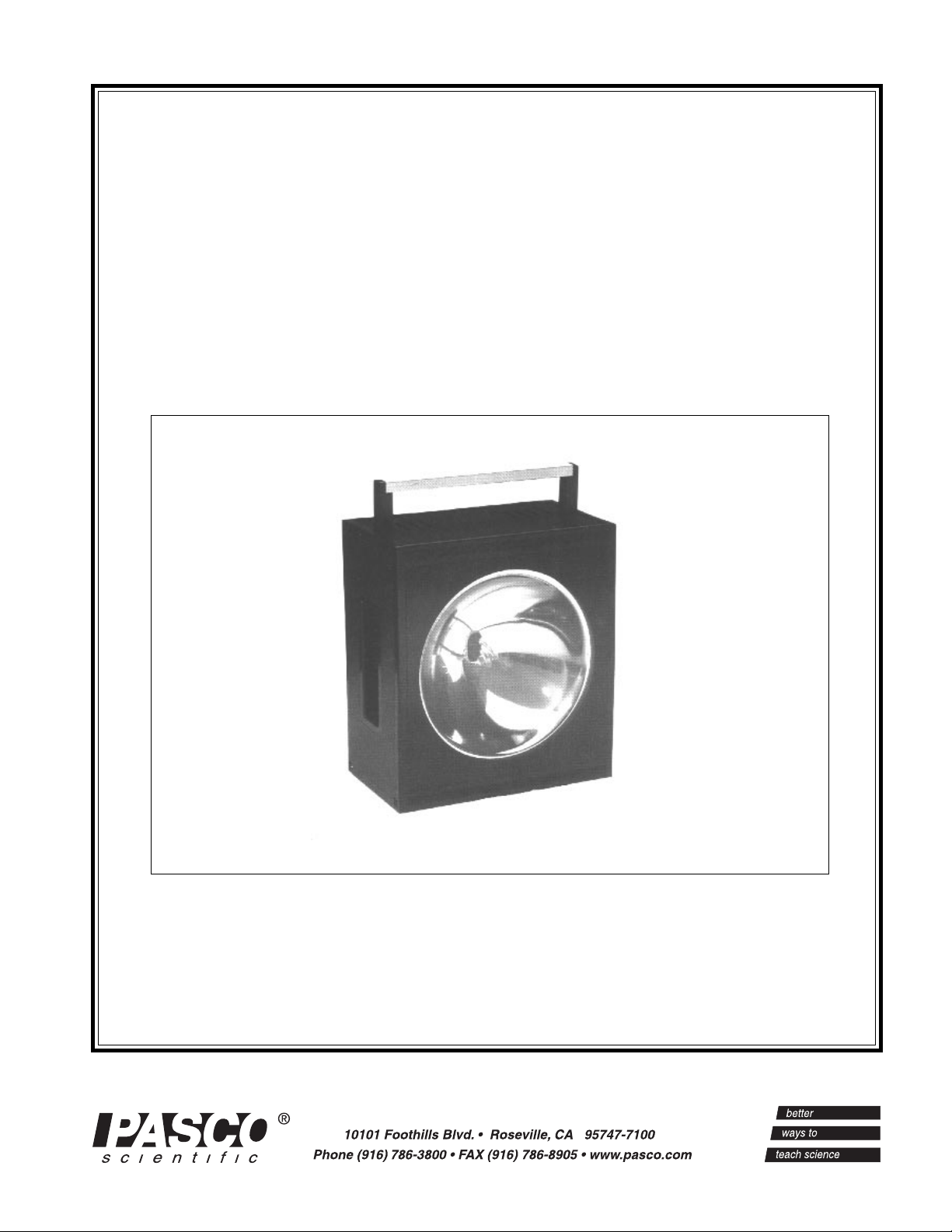
Model SF-9211
STROBOSCOPE
012-02119C
5/94
© 1991 PASCO scientific $5.00
Page 2
Stroboscope 012-02119C
CAUTION
RISK OF ELECTRIC SHOCK
DO NOT OPEN
The lightning flash with arrowhead,
within an equilateral triangle, is intended
to alert the user of the presence of
uninsulated “dangerous voltage” within
the product’s enclosure that may be of
sufficient magnitude to constitute a risk
of electric shock to persons.
CAUTION:
TO PREVENT THE RISK OF
ELECTRIC SHOCK, DO NOT
REMOVE BACK COVER. NO USER
SERVICEABLE PARTS INSIDE.
REFER SERVICING TO QUALIFIED
SERVICE PERSONNEL.
The exclamation point within an equilateral triangle is intended to alert the
user of the presence of important
operating and maintenance (servicing) instructions in the literature accompanying the appliance.
Page 3

012-02119C Stroboscope
T able of Contents
Section Page
Copyright, Warranty, and Equipment Return..................................................ii
Introduction .....................................................................................................1
Features............................................................................................................1
Operation .........................................................................................................2
General Operation
Using the External Trigger
Using the Stroboscope as a Tachometer
Maintenance.....................................................................................................3
Specifications...................................................................................................3
Parts List ..........................................................................................................4
Component Layout ..........................................................................................5
Schematic....................................................................................................... 6,7
Schematic (LED) .............................................................................................8
i
Page 4
Stroboscope 012-02119C
Copyright, Warranty and Equipment Return
Please—Feel free to duplicate this manual
subject to the copyright restrictions below.
Copyright Notice
The PASCO scientific Model SF-9211 Stroboscope
manual is copyrighted and all rights reserved. However,
permission is granted to nonprofit educational institutions
for reproduction of any part of this manual providing the
reproductions are used only for their laboratories and are
not sold for profit. Reproduction under any other circumstances, without the written consent of PASCO scientific,
is prohibited.
Limited Warranty
PASCO scientific warrants this product to be free from
defects in materials and workmanship for a period of one
year from the date of shipment to the customer. PASCO
will repair or replace, at its option, any part of the product
which is deemed to be defective in material or workmanship. This warranty does not cover damage to the product
caused by abuse or improper use. Determination of
whether a product failure is the result of a manufacturing
defect or improper use by the customer shall be made
solely by PASCO scientific. Responsibility for the return
of equipment for warranty repair belongs to the customer.
Equipment must be properly packed to prevent damage
and shipped postage or freight prepaid. (Damage caused
by improper packing of the equipment for return shipment will not be covered by the warranty.) Shipping
costs for returning the equipment, after repair, will be
paid by PASCO scientific.
Equipment Return
Should the product have to be returned to PASCO
scientific for any reason, notify PASCO scientific by
letter, phone, or fax BEFORE returning the product.
Upon notification, the return authorization and
shipping instructions will be promptly issued.
ä
NOTE: NO EQUIPMENT WILL BE
ACCEPTED FOR RETURN WITHOUT AN
AUTHORIZATION FROM PASCO.
When returning equipment for repair, the units
must be packed properly. Carriers will not accept
responsibility for damage caused by improper
packing. To be certain the unit will not be
damaged in shipment, observe the following rules:
➀ The packing carton must be strong enough for the
item shipped.
➁ Make certain there are at least two inches of
packing material between any point on the
apparatus and the inside walls of the carton.
➂ Make certain that the packing material cannot shift
in the box or become compressed, allowing the
instrument come in contact with the packing
carton.
Credits
This manual edited by: Dave Griffith
Address: PASCO scientific
10101 Foothills Blvd.
Roseville, CA 95747-7100
Phone: (916) 786-3800
FAX: (916) 786-3292
email: techsupp@pasco.com
web: www.pasco.com
ii
Page 5
012-02119C Stroboscope
Introduction
The PASCO Model SF-9211 Stroboscope provides
sufficient white light for strobe photography and for
"stopping the motion" during laboratory experiments. The
light is produced with a Xenon flash tube in a 14cm
diameter polished reflector. Flash rate is adjustable from
1-300 flashes per second and a digital display reads the
flash rate in either flashes per second or in RPM. For
added convenience, a threaded hole (1/4-20 UNC-2B) is
provided in the bottom of the unit for mounting the
stroboscope onto a tripod.
A variety of special features enhance the utility of this
stroboscope. For situations requiring synchronized flashes
to large or isolated areas (e.g. separate rooms), it is
possible to synchronize the strobe flashes of a number of
Model SF-9211 Stroboscopes. Each stroboscope
Features
produces a 5 volt output pulse with every flash. This
output may be used as an external trigger that will cause a
simultaneous flash in a second stroboscope. By using the
output signal from each stroboscope to trigger the strobe
flashes of another unit, any number of stroboscopes may
be synchronized.
The ability of the stroboscope to respond to an external
trigger also allows strobe flashes to be synchronized with
some external event. This feature can be used to provide
automatic adjustment of the flash rate in response to rate
changes in the event being observed. It can also insure a
photograph is taken at a critical instant when performing
strobe photography.
To trigger the stroboscope from an external event, a 3-50
volt pulsed signal will trigger the stroboscope.
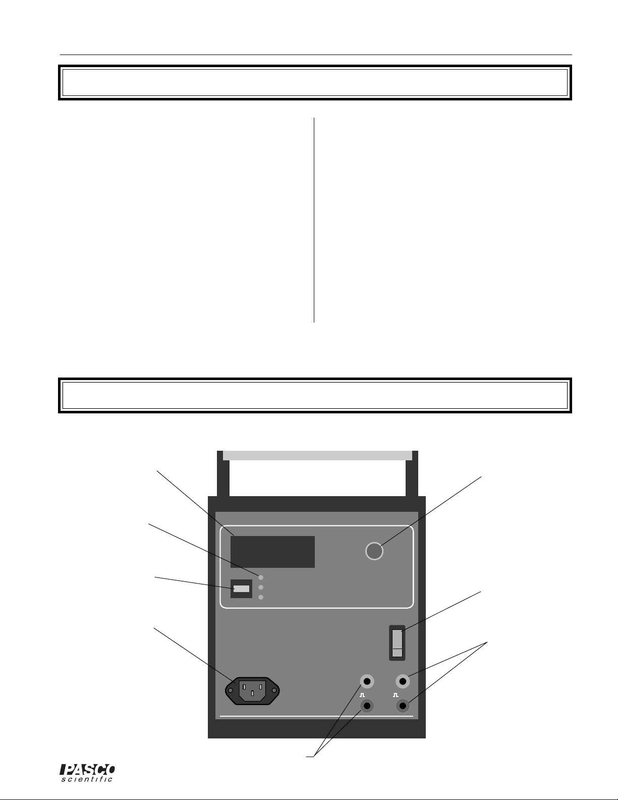
Digital Display
(4-digit LCD)
Display
Selection
LED's
Display
Selection
Switch
Power Cord
Receptacle
FLASHES PER SECOND
R.P.M.
EXT. TRIG.
MODEL SF-9211
STROBOSCOPE
Output Receptacle
Flash Rate
Adjustment Knob
FLASH RATE
ADJUST
On/Off Switch
OFF
POWER
ON
OUTPUT EXT. TRIG.
5V 3-50V
1
External
Trigger
Receptacle
Page 6

Stroboscope 012-02119C
Operation
General Operations
Plug in the stroboscope to a standard 117 volt outlet using
the supplied power cord. Flip the power switch to ON.
The power switch will light, the stroboscope will begin
flashing, and the display will read the flash rate in flashes
per second. To vary the flash rate, turn the FLASH RATE
ADJUST knob located to the right of the display (clockwise increases the rate; counterclockwise decreases the
rate).
The LEDs below the display indicate the mode of
operation. When the unit is turned on, the top LED will
always light, indicating the display is reading in flashes
per second. Pressing the switch located to the left of the
LEDs changes the display units to RPM. Pressing the
switch again will change the mode to External Trigger. In
this mode the stroboscope will only flash if an appropriate
external trigger is provided. Pressing the switch a third
time will return the stroboscope to automatic flash with
the display reading in flashes per second.
Using The External Trigger
As already mentioned, the external trigger can be used to
synchronize the strobe flashes with another stroboscope
or with some external event. Banana plug connectors are
provided for hookups operating in this mode. As labeled
on the control panel of the stroboscope, the output signal
is a 5 volt pulse and the external trigger requires a pulse
from 3-50 volts. (As is standard, the black connectors are
a common ground.)
When operating in external trigger mode, the display
shows the flash rate in flashes per second. Since the unit
must count the flashes over each one second period, the
flash rate is given only to the nearest integer. (The flash
rate reading in this mode is only accurate for flash rates of
at least 10 flashes per second.)
To synchronize the flashes of two stroboscopes, simply
use the OUTPUT signal from one stroboscope to supply
the external trigger for the second. If more than two
synchronized stroboscopes are needed, the output from
the second may be used to trigger a third, and so on. A
daisy-chain of stroboscopes hooked up in this manner
will all flash simultaneously in sync with a flash from the
first. The flash rate of the first stroboscope may be
adjusted manually , or it may be coupled to some other
external trigger.
Using The Stroboscope as a Tachometer
The stroboscope offers an easy method for accurately
measuring the frequency of rotation of a mechanical
system. To do this, mark a convenient point on the
rotating device. Beginning with a flash rate that is clearly
higher than the frequency of the rotating device, adjust
the flash rate until the mark on the device appears stationary. The stroboscope display will then show the frequency of rotation. (If the initial flash rate is not clearly
higher than the frequency of rotation, care must be taken,
as the mark will appear stationary whenever the frequency of rotation is a higher harmonic of the flash rate.)
To trigger the stroboscope from an external event it is
necessary to provide a 3-50 volt pulse that is coupled with
the event. Connect this input to the EXT. TRIG. connectors on the control panel of the stroboscope. (Connect the
signal to the red connector, the signal ground to the
black.) Turn on the stroboscope and switch it to the
External Trigger mode. The stroboscope will now flash
on the descending edge of every trigger pulse.
2
Page 7

012-02119C Stroboscope
Maintenance
➤WARNING: High voltages are involved in the
normal functioning of this unit. Troubleshooting
should be performed only by trained personnel. Please
contact PASCO scientific if service is required.
This stroboscope should provide long and trouble free
service. It should be cleaned periodically, using a nonabrasive cleaner to avoid scratching the plastic window.
Beyond this, no regular maintenance is required.
Specifications
Size: 24x18x12 cm.
Power Requirements: 117 VAC, 60HZ
Flash Rate: 1-300 flashes per second: 60-18,000 RPM
Should the power switch fail to light when the stroboscope is turned on , there may be a blown fuse (Over
time, the power switch may begin to flicker when it is
turned on. This does not affect the function of the stroboscope). To replace the fuse, turn off and unplug the
stroboscope. Remove the four screws that attach the left
side panel of the unit (facing the control panel). Remove
the side panel. The fuse is located near the bottom left
corner of the printed circuit board, facing the display side
of the unit. If the fuse is blown, replace it with a similar
250 mA fuse.
Tube Life: 250 hours/270 million flashes
Sync Signals:
Output Signal: 5-7 Volt pulse
Flash Energy (Joules): 1-16 Hz = 1.47
16-64 Hz = 0.18
64-300 Hz = 0.033
Current Pulse Width: 5µs
Arc Length (electrode spacing): = 80mm
Bore Diameter (I.D. of flash tube): = 6.0mm
External Trigger Requirements: 3-50 Volt;
Triggers on falling edge of pulse
Equipment Included: Power cord, Instruction manual
➤NOTE: The stroboscope undergoes two changes
in flash intensity: one at approximately 16 Hz and
the second at approximately 64 Hz. The overall
light output, however, will remain constant.
3
Page 8

Stroboscope 012-02119C
Parts List
Item No. Quantity Reference Part
1 2 C1,C2 33µF 350V
2 1 C3 47nF 400V
31 C4 µ22 1KV
41 C5 8µF 400V
51 C6 1µF 250V
6 3 C7, C19, C22 100nF 160V
7 3 C8, C12, C13 1µ5 63V
8 2 C9, C24 220nF 100V
9 4 C10, C11, C15, C20 1nF
10 1 C14 22nF
11 2 C16, C17 27pF
12 1 C18 100nF 100V
13 1 C21 2200µF 25V
14 1 C23 33µF 25V
15 1 C25 220nF 63V
16 1 C26 22µF 25V
17 2 D1, D2 1N5408
18 1 D3 3V9
19 1 D4 BAW62
20 1 D5 W02M
21 2 D6, D7 1N4148
22 1 F1 250mAT 250V
23 1 J1 777
24 1 LAMP A LAMP
25 1 L1 ZS1052-11
26 1 P1 100KA POT
27 1 Q1 BC338
28 2 Q2, Q4 BC557
29 2 Q3, Q6 BC547
30 1 Q5 106D1
31 2 RE1, RE2 A 002 43 05
32 1 R1 330K
33 1 R2 100K
34 1 R3 1M
35 2 R4, R5 R82 5W
36 1 R6 6K8 15W
37 2 R7, R10 270K
38 9 TR4, R8, R9, R11, R12, 10K
R13, R19, R20, R21
39 2 R14, R25 10K SIL
40 1 R15 39K
41 1 R16 56K
42 1 R17 18M
43 1 R18 6K8
44 2 R22, R26 1K
Item No. Quantity Reference Part
45 1 R23 470Ω
46 2 R24, R29 4K7
47 1 R27 S10K 17V
48 1 R28 2K2
49 1 R30 27K
50 1 SW? SW MK2
51 1 SW1 c5403f
52 2
53 1 TF1 DT 9099-1 (220V)
1 TF1 NT 15293 (117V)
54 1 TR1 4M7 TRIM
55 1 TR2 1M TRIM
56 1 TR5 10K TRIM
57 1 T1 SH 203
58 2 U1, U2 4040
59 3 U3, U4, U5 4017
60 5 U6, U7, U8, U9, U10 4011
61 1 U11 NE555
62 1 U12 4521
63 1 U13 LM7808
64 1 U14 4528
65 1 U15 4071
66 1 U16 4081
67 1 U17 4001
68 1 X1 4194.304
69 5 DS101, DS102, DS103 HDSP 5301
70 1 D8 3V3
71 3 D101, D102, D103 LED
72 2 Q101, Q102 BC547
73 1 R101 150 Ω
74 1 R102 120 Ω
75 2 R103, R104 10K
76 1 R105 1K
77 3 R106, R107, R108 470Ω
78 1 U101 2981A
79 1 U102 4013
80 1 U103 74C926
81 1 U105 2003
T
ERMINAL B, TERMINAL
TERMINAL A
DS104, DS105
4
Page 9

012-02119C Stroboscope
Component Layout
Position of Components
(Dwg. #952-02110)
5
Page 10

Stroboscope 012-02119C
Schematic
Stroboscope Schematic
(Dwg. #956-02109 1/2)
6
Page 11

012-02119C Stroboscope
Stroboscope Schematic
(Dwg. #956-02109 2/2)
7
Page 12

Stroboscope 012-02119C
Schematic LED
Stroboscope Schematic
(Dwg. #956-02109 1/2)
8
Page 13

012-02119C Stroboscope
T echnical Support
Feed-Back
If you have any comments about this product or this
manual please let us know. If you have any suggestions on alternate experiments or find a problem in the
manual please tell us. PASCO appreciates any customer feed-back. Your input helps us evaluate and
improve our product.
To Reach PASCO
For Technical Support call us at 1-800-772-8700 (tollfree within the U.S.) or (916) 786-3800.
Contacting Technical Support
Before you call the PASCO Technical Support staff it
would be helpful to prepare the following information:
• If your problem is with the PASCO apparatus, note:
Title and Model number (usually listed on the label).
Approximate age of apparatus.
A detailed description of the problem/sequence of
events. (In case you can't call PASCO right away,
you won't lose valuable data.)
If possible, have the apparatus within reach when
calling. This makes descriptions of individual parts
much easier.
• If your problem relates to the instruction manual,
note:
Part number and Revision (listed by month and year
on the front cover).
Have the manual at hand to discuss your questions.
Page 14

 Loading...