

Page 1
Instruction Manual and
Experiment Guide for the
PASCO scientific Model
012-04046C
5/92
SF-8607 and SF-8608
Basic Current Balance
and
Current Balance Accessory
SF-8607
Basic Current Balance
SF-8608
Current Balance Accessory
Copyright © June 1989 $5.00
Page 2

Basic Current Balance and Accessory 012-04046C
scientific
Page 3
012-04046C Basic Current Balance and Accessory
T able of Contents
Section Page
Copyright, Warranty, and Equipment Return............................................... ii-iii
Introduction .....................................................................................................1
Equipment........................................................................................................2
Operation .........................................................................................................3
Experiments
Experiment 1 Force versus Current ....................................................5
Experiment 2 Force versus Length of Wire........................................6
Experiment 3 Force versus Magnetic Field........................................7
Experiment 4 Force versus Angle ......................................................8
Maintenance.....................................................................................................9
scientific
i
Page 4
Basic Current Balance and Accessory 012-04046C
Copyright, Warranty and Equipment Return
Please—Feel free to duplicate this manual
subject to the copyright restrictions below.
Copyright Notice
The PASCO scientific Model SF-8607 Basic Current
Balance and SF-8608 Current Balance Accessory
manual is copyrighted and all rights reserved. However, permission is granted to non-profit educational
institutions for reproduction of any part of this manual
providing the reproductions are used only for their
laboratories and are not sold for profit. Reproduction
under any other circumstances, without the written
consent of PASCO scientific, is prohibited.
Limited Warranty
PASCO scientific warrants this product to be free
from defects in materials and workmanship for a
period of one year from the date of shipment to the
customer. PASCO will repair or replace, at its option,
any part of the product which is deemed to be defective in material or workmanship. This warranty does
not cover damage to the product caused by abuse or
improper use. Determination of whether a product
failure is the result of a manufacturing defect or
improper use by the customer shall be made solely by
PASCO scientific. Responsibility for the return of
equipment for warranty repair belongs to the customer. Equipment must be properly packed to prevent
damage and shipped postage or freight prepaid.
(Damage caused by improper packing of the equipment for return shipment will not be covered by the
warranty.) Shipping costs for returning the equipment, after repair, will be paid by PASCO scientific.
Equipment Return
Should the product have to be returned to PASCO
scientific for any reason, notify PASCO scientific by
letter, phone, or fax BEFORE returning the product.
Upon notification, the return authorization and
shipping instructions will be promptly issued.
ä
NOTE: NO EQUIPMENT WILL BE
ACCEPTED FOR RETURN WITHOUT AN
AUTHORIZATION FROM PASCO.
When returning equipment for repair, the units
must be packed properly. Carriers will not accept
responsibility for damage caused by improper
packing. To be certain the unit will not be
damaged in shipment, observe the following rules:
➀ The packing carton must be strong enough for the
item shipped.
➁ Make certain there are at least two inches of
packing material between any point on the
apparatus and the inside walls of the carton.
➂ Make certain that the packing material cannot shift
in the box or become compressed, allowing the
instrument come in contact with the packing
carton.
Address: PASCO scientific
10101 Foothills Blvd.
Roseville, CA 95747-7100
Phone: (916) 786-3800
FAX: (916) 786-3292
email: techsupp@pasco.com
web: www.pasco.com
ii
scientific
Page 5
012-04046C
Current Balance and Accessory
Introduction
A current-carrying wire in a magnetic field experiences a force that is usually referred to as a magnetic
force. The magnitude and direction of this force
depend on four variables: the magnitude of the current
(I); the length of the wire (L); the strength of the
magnetic field (B); and the angle between the field and
the wire (θ).
This magnetic force can be described mathematically
by the vector cross product:
F
= IL X B,
m
or in scalar terms,
= ILBsinθ.
F
m
With the PASCO SF-8607 Basic Current Balance, you
can vary three of the variables in the equation—the
current, the length of the wire, and the strength of the
magnetic field—and measure the resulting magnetic
force. By adding the SF-8608 Current Balance
Accessory, you can also vary the angle between the
wire and the magnetic field, thereby performing a
complete investigation into the interaction between a
current carrying wire and a magnetic field.
This manual supplies general operating instructions for
both the SF-8607 Basic Current Balance and the
SF-8608 Current Balance Accessory. Step-by-step
instructions for four experiments are also included.
scientific
1
Page 6

Current Balance and Accessory
012-04046C
Equipment
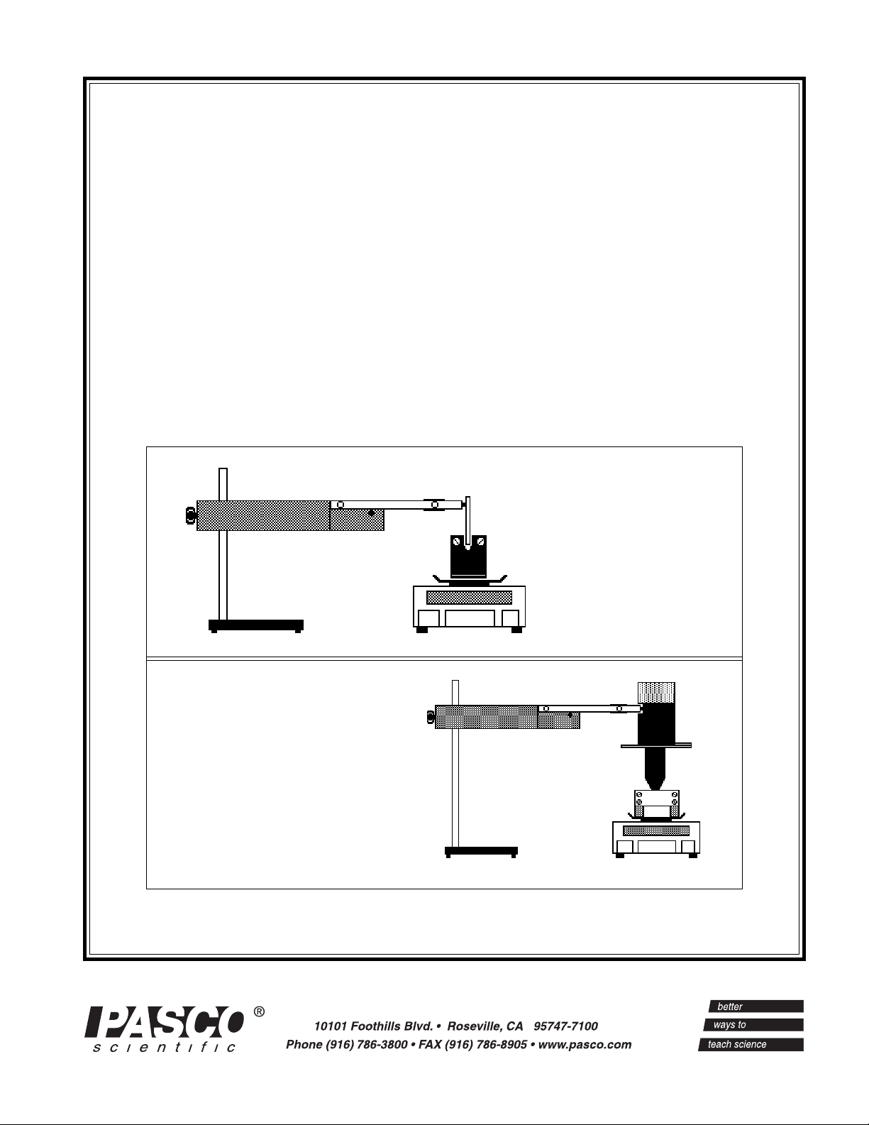
The SF-8607 Basic Current Balance
Your SF-8607 Basic Current Balance includes the
items shown in Figure 1:
• Main Unit,
• six Current Loop PC boards
• Magnet Assembly with six magnets.
Additional Equipment Needed:
In addition to the included equipment, you will need
the following items to perform the experiments in this
manual:
• DC power supply capable of supplying up to 5 A
such as the PASCO Model SF-9584.
• DC ammeter capable of measuring up to 5 A such
as the PASCO Model SB-9624.
• Balance capable of measuring forces with an accuracy of 0.01 gram mass equivalent. The balance
can be either a quadruple beam balance, such as
the PASCO Model SE-8725, or an electronic top
loading balance such as the PASCO Model SE-
8709.
• Lab stand such as the PASCO Model ME-9355.
• Hook-up wires with banana plug connectors such
as the PASCO Models SE-9750 (red) and SE-9751
(black).
The SF-8608 Current Balance Accessory
Your SF-8608 Current Balance Accessory includes the
items shown in figure 2:
• the Current Balance Accessory Unit
• Magnet Assembly.
Additional Equipment Needed:
• The Main Unit from the SF-8607 Basic Current
Balance plus additional equipment as listed above
under additional equipment for the SF-8607.
Magnet Assembly
Magnet Assembly
Current Balance Accessory Unit
Current Balance Accessory Unit
Figure 2 Equipment Included with the SF-8608 Current
Balance Accessory.
Main Unit
Current Loops
Figure 1 Equipment Included with the SF-8607 Basic
Current Balance.
Magnet Assembly
2
scientific
Page 7

012-04046C
3.00e-1
Current Balance and Accessory
Operation
The SF-8607 Basic Current Balance
To set up the Current Balance (see Figure 3):
Current Loop
Main Unit
Lab Stand
Figure 3 Setting Up the SF-8607 Basic Current Balance
Magnet
Assembly
0.01 gram
Balance
➀ Mount the Main Unit on a lab stand having with a rod
3/8 inch (1.1 cm) in diameter or smaller.
➁ Select a Current Loop, and plug it into the ends of the
arms of the Main Unit, with the foil extending down.
➂ Place the Magnet Assembly on a balance with at least
0.01 gram sensitivity. Position the lab stand so the
horizontal portion of the conductive foil on the Current Loop passes through the pole region of the magnets. The Current Loop shouldn't touch the magnets.
Connect the power supply and ammeter as shown in
➃
Figure 4.
If you are using a quadruple-beam balance:
First measure the weight of the Magnet Assembly with
no current flowing (F
). Then turn on the current, adjust
0
it to the desired level, and measure the weight of the
Magnet Assembly with current flowing (F
). With
I
current flowing, the reading will be higher or lower than
before. The difference in weight (F
– F0) is proportional
I
to the force exerted on the magnetic field (and thereby
the magnets) by the current-carrying wire. To investigate the relationship between current and force, vary the
current and measure the weight at each value.
If you are using a top-loading electronic balance:
With the Magnet Assembly sitting on the balance, tare
the reading by pressing the appropriate switch on the
balance. This subtracts the weight of the Magnet
Assembly from ensuing weight measurements, so only
the force caused by the current will be measured. Turn
the current on. If the reading is negative, reverse the
leads where they plug into the arms of the Main Unit.
The measured weight is directly proportional to the force
caused by the current moving through the magnetic
field.
Force vs. Current for SF-8607
Power Supply
Base Unit
Figure 4 Connecting the Ammeter and Power Supply
Ammeter
0-5A (Max.)
Measuring the Force
➧ Note: In this manual, we use the balance reading
in grams as our measure of force. Most students
will realize that the mass reading is proportional to
the actual force, which is given by the equation
F = mg. If you wish to use the actual force value,
simply multiply each reading in grams by 0.0098
newtons/gram to arrive at a force in newtons, or by
980 dynes/gram to arrive at a force in dynes.
scientific
2.00e-1
1.00e-1
Force, grams
1.36e-20
01234
Current, amps
Figure 5 Typical Data for Force versus Current
Measurements
Varying the Wire Length
Vary the wire length by using one of the six different
Current Loops. To change the Current Loop:
➀ Swing the arm of the Main Unit up, to raise the
present Current Loop out of the magnetic field gap.
Pull the Current Loop gently from the arms of the
base unit. Replace it with a new Current Loop and
3
Page 8

Current Balance and Accessory
012-04046C
carefully lower the arm to reposition the Current
Loop in the magnetic field. Six Current Loops are
supplied with the SF-8607 Basic Current Balance
Kit. The lengths are:
Current Loop Length
SF 40 1.2 cm
SF 37 2.2 cm
SF 39 3.2 cm
SF 38 4.2 cm
SF 41 6.4 cm
SF 42 8.4 cm
The lengths above were measured at the maximum
length of the current-carrying wire foil. The effective
length may be somewhat shorter, as much as 0.2 cm for
single lengths and 0.4 cm for doubled lengths (doubled
lengths refer to Current Loops in which the current
passes between the magnet poles twice, once on each
side of the PC board).
Force vs Length for SF-8607
6.00e-1
5.00e-1
4.00e-1
3.00e-1
2.00e-1
1.00e-1
-1.36e-20
0 20406080100
Length, mm
Figure 6 Typical Data for Force versus Wire Length
Measurements
Force vs No. of Magnets for SF-8607
0.15
0.10
0.05
Varying the Magnetic Field
The magnetic field is varied by changing the number of
magnets that are mounted on the Magnet Assembly. (We
recommend you mark the north pole of each magnet, to
help students during setup.) The magnetic field strength
may not be exactly proportional to the number of magnets, but it is reasonably close, as seen by the data in
Figure 7.
SF-8608 Current Balance Accessory
Using the SF-8608 Current Balance Accessory, you can
determine how the angle between the current-carrying
wire and the magnetic field affects the force between
them. The basic experimental setup is shown in Figure 8.
Main Unit
SF-8608
Accessory
Unit
Lab Stand
Figure 8 Setup for the SF-8608 Current Balance
Accessory.
Magnet
Assembly
0.01 gram
Balance
➧ Note: The SF-8608 Current Balance Accessory
can also be used to experiment with the relationship
between current and force by holding the angle
steady and varying the current.
➧ Warning: The current through the SF-8608
Current Balance Accessory should never exceed
2.0 amps.
➀ Set the dial on the unit to 0
o
.
➁ Align the Magnet Assembly so that the magnetic field
is approximately parallel with the wires of the coil.
➂ With the current turned off, measure the weight of the
Magnet Assembly, or if you are using an electronic
balance, tare the balance.
Two different lengths of loop
0.00
01234567
No. Magnets
Figure 7 Typical Data for Force versus Wire Length
Measurements
Set the current to a value of 2.0 amps. Take a new
➃
reading and record this in your data table. Rotate the
dial clockwise in 5
o
increments, taking new readings
each at each setting. Then rotate the dial counterclockwise in 5
o
increments. The resulting graph of
Force vs Angle should be a sine curve.
4
scientific
Page 9

012-04046C
Experiment 1: Force versus Current
Procedure
If you're using a quadruple-beam balance:
➀ Set up the apparatus as shown in figure 1.1.
Current Balance and Accessory
➁ Determine the mass of the magnet holder and
magnets with no current flowing. Record this value
in the column under “Mass” in Table 1.1.
➂ Set the current to 0.5 amp. Determine the new
Main Unit
“mass” of the magnet assembly. Record this value
under “Mass” in Table 1.1.
Subtract the mass value with the current flowing
➃
Lab Stand
0.01 gram
Balance
from the value with no current flowing. Record this
difference as the “Force.”
Figure 1.1 Equipment Setup
➄ Increase the current in 0.5 amp increments to a
maximum of 5.0 amp, each time repeating steps 2-4.
If you're using an electronic balance:
➀ Set up the apparatus as shown in figure 1.1.
➁ Place the magnet assembly on the pan of the balance. With no current flowing, press the
TARE button, bringing the reading to 0.00 grams.
➂ Now turn the current on to 0.5 amp, and record the mass value in the “Force” column of Table
1.1.
Increase the current in 0.5 amp increments to a maximum of 5.0 amp, each time recording the
➃
new “Force” value.
Current Loop
Magnet
Assembly
Data Processing
Plot a graph of Force (vertical axis) versus Current (horizontal axis).
Analysis
What is the nature of the relationship between these two variables? What does this tell us
about how changes in the current will affect the force acting on a wire that is inside a magnetic
field?
scientific
Table 1.1 Data
Current “Mass” “Force”
( amps) ( gram) (gram)
0.0
0.5
1.0
1.5
2.0
2.5
Current “Mass” “Force”
( amps) ( gram) (gram)
3.0
3.5
4.0
4.5
5.0
5
Page 10

Current Balance and Accessory
Experiment 2: Force versus Length of Wire
Procedure
➀
Set up the apparatus as in Figure 2.1.
➁ Determine the length of the conductive foil on the
Current Loop. Record this value under “Length”
in Table 2.1.
If you are using a quadruple-beam balance:
Main Unit
012-04046C
Current Loop
Magnet
Assembly
➂ With no current flowing, determine the mass of
the Magnet Assembly. Record this value on the
Lab Stand
0.01 gram
Balance
line at the top of Table 2.1.
Set the current to 2.0 amps. Determine the new
➃
Figure 2.1 Equipment Setup
“mass” of the Magnet Assembly. Record this
value under “Mass” in Table 2.1.
➄ Subtract the mass that you measured with no current flowing from the mass that you measured
with the current flowing. Record this difference as the “Force.”
Turn the current off. Remove the Current Loop and replace it with another. Repeat steps 2-5.
➅
If you are using an electronic balance:
➂ Place the magnet assembly on the pan of the balance. With no current flowing, press the
TARE button, bringing the reading to 0.00 grams.
Now turn the current on, and adjust it to 2.0 amps. Record the mass value in the “Force”
➃
column of Table 2.1.
➄ Turn the current off, remove the Current Loop, and replace it with another. Repeat steps 2-4.
Data Processing
Plot a graph of Force (vertical axis) versus Length (horizontal axis).
Analysis
What is the nature of the relationship between these two variables? What does this tell us
about how changes in the length of a current-carrying wire will affect the force that it feels
when it is in a magnetic field?
“Mass” with I=0: ___________
Length “Mass” “Force”
(mm) (gram) (gram)
Table 2.1 Data
6
Length “Mass” “Force”
(mm) (gram) (gram)
scientific
Page 11

012-04046C
Experiment 3: Force versus Magnetic Field
Procedure
Set up the apparatus as shown in Figure 2.1. Use the shortest length current loop.
➀
If you are using a quadruple-beam balance:
➁ Mount a single magnet in the center of the holder.
➂ With no current flowing, determine the mass of the Magnet Assembly. Record this value in
the first column under “Mass” in Table 3.1 on the appropriate line.
Set the current to 2.0 amps. Determine the new “mass” of the Magnet Assembly. Record
➃
this value in the second column under “Mass” in Table 3.1.
➄ Subtract the mass you measured when there was no current flowing from the value you
measured with current flowing. Record this difference as the “Force.”
Add additional magnets, one at a time. (Make sure the north poles of the magnets are all on
➅
the same side of the Magnet Assembly.) Each time you add a magnet, repeat steps 3-5.
Current Balance and Accessory
If you use an electronic balance:
➁ Use a single magnet, centered under the center of the holder.
➂ Place the magnet assembly on the pan of the balance. With no current flowing, press the
TARE button, bringing the reading to 0.00 grams.
Now turn the current on, and adjust it to 2.0 amps. Record the mass value in the “Force”
➃
column of Table 3.1.
➄ Add additional magnets, one at a time. (Make sure the north poles of the magnets are all on
the same side of the Magnet Assembly.) Each time you add a magnet, repeat steps 3-5.
Data Processing
Plot a graph of Force (vertical axis) versus Number of Magnets (horizontal axis).
Analysis
What is the relationship between these two variables? How does the number of magnets
affect the force between a current-carrying wire and a magnetic field? Is it reasonable to
assume that the strength of the magnetic field is directly proportional to the number of
magnets? What would happen if one of the magnets were put into the assembly backwards,
with its north pole next to the other magnets’ south poles? If there is time, try it.
Table 3.1 Data
”Mass”
Number of I = 0 I ≠ 0 “Force”
Magnets gram gram gram
1
2
3
scientific
”Mass”
Number of I = 0 I ≠ 0 “Force”
Magnets gram gram gram
4
5
6
7
Page 12

Current Balance and Accessory
Experiment 4: Force versus Angle
Procedure
1. Set up the apparatus as shown in Figure 4.1.
If you are using a quadruple-beam balance:
2. Determine the mass of the Magnet Assembly with
no current flowing. Record this value in Table 4.1
on the appropriate line.
o
3. Set the angle to 0
with the direction of the coil of
wire approximately parallel to the magnetic field.
Set the current to 1.0 amp. Determine the new
“mass” of the Magnet Assembly. Record this
value under “Mass” in Table 4.1.
4. Subtract the mass measured with no current
flowing from the mass measured with current flowing. Record the difference as the “Force.”
o
5. Increase the angle in 5
increments up to 90o, and then in –5o increments to –90o. At each
angle, repeat the mass/force measurement.
If you are using an electronic balance:
2. Place the magnet assembly on the pan of the balance. With no current flowing, press the
TARE button, bringing the reading to 0.00 grams.
o
3. Set the angle to 0
with the direction of the coil of wire approximately parallel to the magnetic
field. Set the current to 1.0 amp. Record the mass value in the “Force” column of Table 4.1.
o
4. Increase the angle in 5
increments up to 90o, and then in –5o increments to –90o. At each
angle, repeat the mass/force measurement.
Main Unit
SF-8608
Accessory
Unit
Lab Stand
Figure 4.1 Equipment Setup
0.01 gram
Balance
012-04046C
Magnet
Assembly
Data Processing
Plot a graph of Force (vertical axis) versus Angle (horizontal axis).
Analysis
What is the relationship between these two variables? How do changes in the angle between
the current and the magnetic field affect the force acting between them? What angle produces
the greatest force? What angle produces the least force?
Angle “Mass” “Force”
(θ) (gram) (gram)
0
5
10
15
20
25
30
35
40
45
Table 4.1 Data
Angle “Mass” “Force”
(θ) (gram) (gram)
50
55
60
65
70
75
80
85
90
Angle “Mass” “Force”
(θ) (gram) (gram)
0
–5
–10
–15
–20
–25
–30
–35
–40
–45
8
“Mass” with I = 0: _________
Angle “Mass” “Force”
(θ) (gram) (gram)
–50
–55
–60
–65
–70
–75
–80
–85
–90
scientific
Page 13

012-04046C
Current Balance and Accessory
Maintenance
STORAGE
(see Figure 9)
When storing your SF-8607 Basic Current Balance, we
recommend that you alternate the magnets so they have their
north poles next to south poles for maximum retention of
field strength. The Magnet Assembly from the SF-8608
Current Balance Accessory should have a “keeper” made of
soft iron placed across the pole pieces to help retain the
magnetism of the magnets.
Iron or Steel
SN
N
S
SF-8608 Magnet AssemblySF-8607 Magnets
Figure 9 Storing the Magnets
"Keeper"
CUSTOMER SERVICE
For service problems, please call (toll-free 1-800-772-8700)
and ask for customer service.
scientific
9
Page 14

Current Balance and Accessory
012-04046C
Notes:
10
scientific
 Loading...