

Page 1
Instruction Manual
No. 012-09301A
Discover Reflection Kit
SE-8803
Included Equipment
Plane mirror with stand (15 cm x 15 cm)
Corkboard (22 cm x 28 cm)
Colored pins
Additional Equipment Recommended
Protractor
Ruler or straight edge
Pencil
Page 2
Discover Reflection Kit 012-09301A
Introduction
The Discover Reflection Kit allows students to derive the Law of Reflection and to determine
the Field of Vision.
To derive the Law of Reflection, students place a pin in front of the mirror. A location
elsewhere in front of the mirror is chosen as the location of the eye. Light rays are drawn from
the pin to the mirror and then to the eye. The process is repeated for several locations of the
eye. For each reflected ray, a perpendicular line is drawn at the surface of the mirror. A
protractor can then be used to prove that the angle of incidence is equal to the angle of
reflection.
To determine the Field of Vision, students place a pin in front of the mirror. They move their
eye from left to right to determine the furthest point on each side of the mirror from which the
image of the pin can be seen.
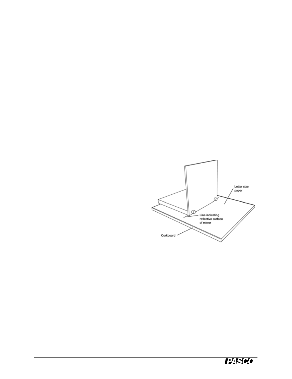
Equipment Setup
1. Place a sheet of paper on the corkboard.
2. Place the mirror on top of the paper as in
the picture to the right.
3. Look at one side of the mirror and locate
the position where the black support
meets the mirror. Place a small dot on the
paper to mark this position. Repeat this
step for the other side of the mirror.
4. Remove the mirror from the paper and
use a ruler to connect the two dots. This
line represents the position of the mirror,
since this is a rear surface mirror.
5. Replace the mirror on this line, such that the mirrored surface lies along it.
2
®
Page 3

012-09301A Discover Reflection Kit
Suggested Activities
The Law of Reflection
Purpose:
Students will discover the relationship between the angle of incidence and the angle of
reflection. Virtual image formation will also be investigated.
Note: Before the lab, it may be necessary to define "Angle of Incidence" and "Angle of
Reflection."
Equipment Required:
• Plane mirror with stand
• Corkboard
• Colored pins
• Protractor
• Straight edge
•Pencil
Procedure:
1. Set up the apparatus as instructed in the "Equipment Setup" section.
2. Place a pin approximately 12 cm in front of the mirror and approximately 7 cm to the right
of center. Label this position "A."
3. Choose a point on the left side of the mirror
and label it "B." Draw an eye at this
position.
4. Position your eye behind the eye at position
"B" such that the image from pin "A" is in
line with the eye at position "B."
5. In order to see the image of pin "A," a light
ray has to leave pin "A" and reach your eye
at position "B."
6. Use a straight edge or ruler to draw the path
of the light ray as it leaves pin "A," reflects
off the mirror, and reaches your eye at
position "B."
7. Draw a dashed line perpendicular to the mirror where the ray reflects from the mirror. This
is called a normal line.
®
3
Page 4

Discover Reflection Kit 012-09301A
8. Using a protractor, measure the angle of incidence and the angle of reflection. Enter them
into Data Table 1.
9. Repeat steps 3-8 for 3 more positions (C, D, E) on the left side of the mirror.
10. Remove the mirror from the paper and use a straight edge to extend each of the reflected
light rays behind the mirror. Use dotted lines to illustrate that the light rays from pin "A"
don't actually go through the mirror.
Data Table 1
Location Angle of Incidence
(Degrees)
B
C
D
E
Angle of Reflection
(Degrees)
Questions
1. Describe the relationship between the angle of incidence and the angle of reflection.
2. A 2.0 m tall woman wants to buy the shortest mirror that will allow her to view her entire
body. What height should the mirror be?
3. How high on the wall must the mirror hang? Explain.
4. Describe the image of pin "A." Where is it located relative to the mirror and to the actual
pin? What is its size compared to the actual pin?
5. Why does the eye "believe" that an image of the pin "A" exists behind the mirror?
4
®
Page 5

012-09301A Discover Reflection Kit
Field of Vision
Purpose:
Students will determine the field of vision for a given location in front of the mirror.
Equipment required:
• Plane mirror with stand
• Corkboard
• Colored pins
• Protractor
• Straight edge
•Pencil
Procedure:
1. Set up the apparatus as instructed in the "Equipment Setup" section.
2. Place a pin approximately 4 cm in front of
the center of the mirror.
3. Move your eye to the left side of the mirror
until the image of the pin is just at the edge of
the mirror. Draw a small eye at this position.
4. Use a straight edge or ruler to draw the path
of the light ray as it leaves the pin, reflects off
the mirror, and reaches your eye at this
position.
5. Move your eye to the right side of the mirror until the image of the pin is at the edge of the
mirror. Draw a small eye at this position.
6. Use a straight edge or ruler to draw the path of the light ray as it leaves the pin, reflects off
the mirror, and reaches your eye at this position.
7. Repeat steps 3-6 for pin locations 8 cm and 12 cm away from the mirror.
Questions
1. Define field of vision in your own words.
2. What happens to the field of vision as an observer moves away from the mirror?
3. What determines the field of vision?
4. Sketch a top view of a car including the rear view and side view mirrors. Using your
sketch, draw the field of vision for each mirror. Label the "blind spots."
®
5
Page 6

012-09301A Discover Reflection Kit
Safety
Read the instructions before using this
product. Students should be supervised
by their instructors. When using this
product, follow the instructions in this
manual and all local safety guidelines
that apply to you.
Technical Support
For assistance with any PASCO product,
contact PASCO at:
Address: PASCO scientific
10101 Foothills Blvd.
Roseville, CA 95747-7100
Phone: (916) 786-3800
(800) 772-8700
Fax: (916) 786-3292
Web: www.pasco.com
Email: support@pasco.com
Limited Warranty
For a description of the product warranty,
see the PASCO catalog.
Copyright Notice
The P ASCO scientific 012-09301A Discover
Reflection Kit Manual is copyrighted with all
rights reserved. Permission is granted to
non-profit educational institutions for
reproduction of any part of this manual,
providing the reproductions are used only in
their laboratories and classrooms, and are not
sold for profit. Reproduction under any other
circumstances, without the written consent
of PASCO scientific, is prohibited.
6
®
 Loading...