

Page 1
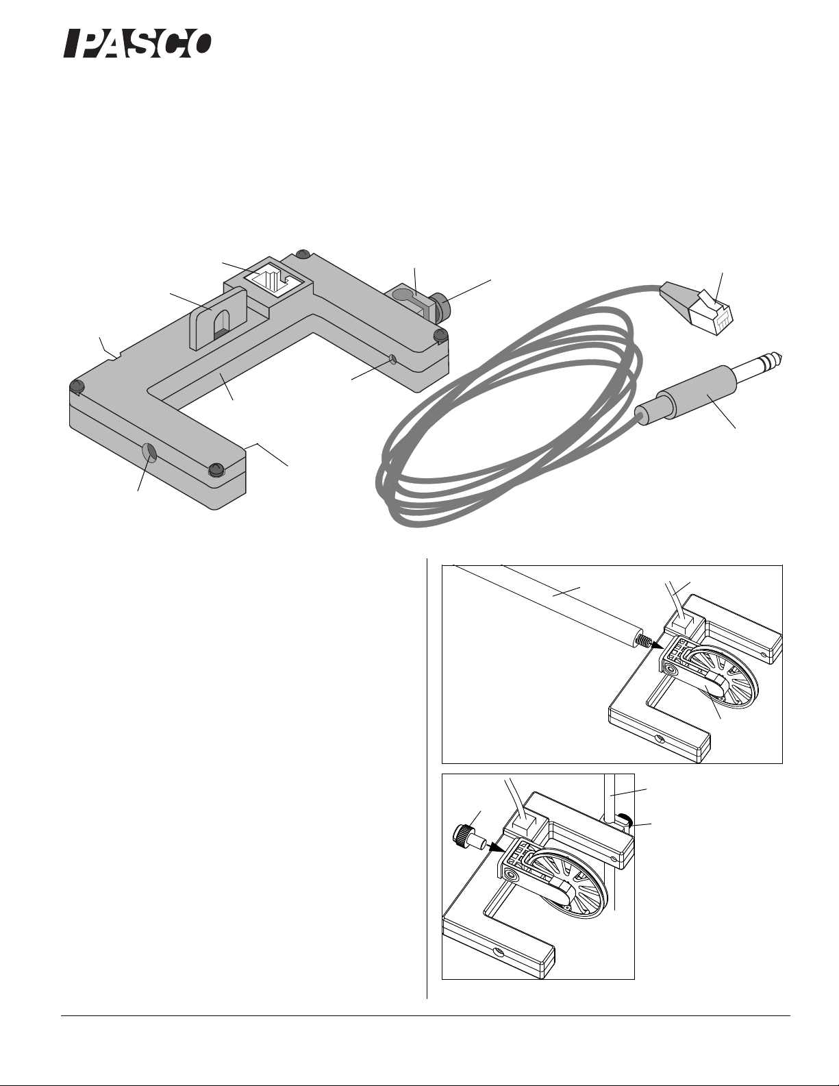
Photogate Head
®
Photogate
Head
Small Rod Clamp
Thumbscrew
Photogate Cable
Phone Plug
RJ12 Plug
RJ12 Jack
1/4-20 Threaded Hole
Slot for attaching
a Super Pulley.
Infrared
Source
Infrared
Detector
(not shown)
LED (not
shown)
Pulley Mounting Rod
(SA-9242)
Super Pulley
(ME-9450A)
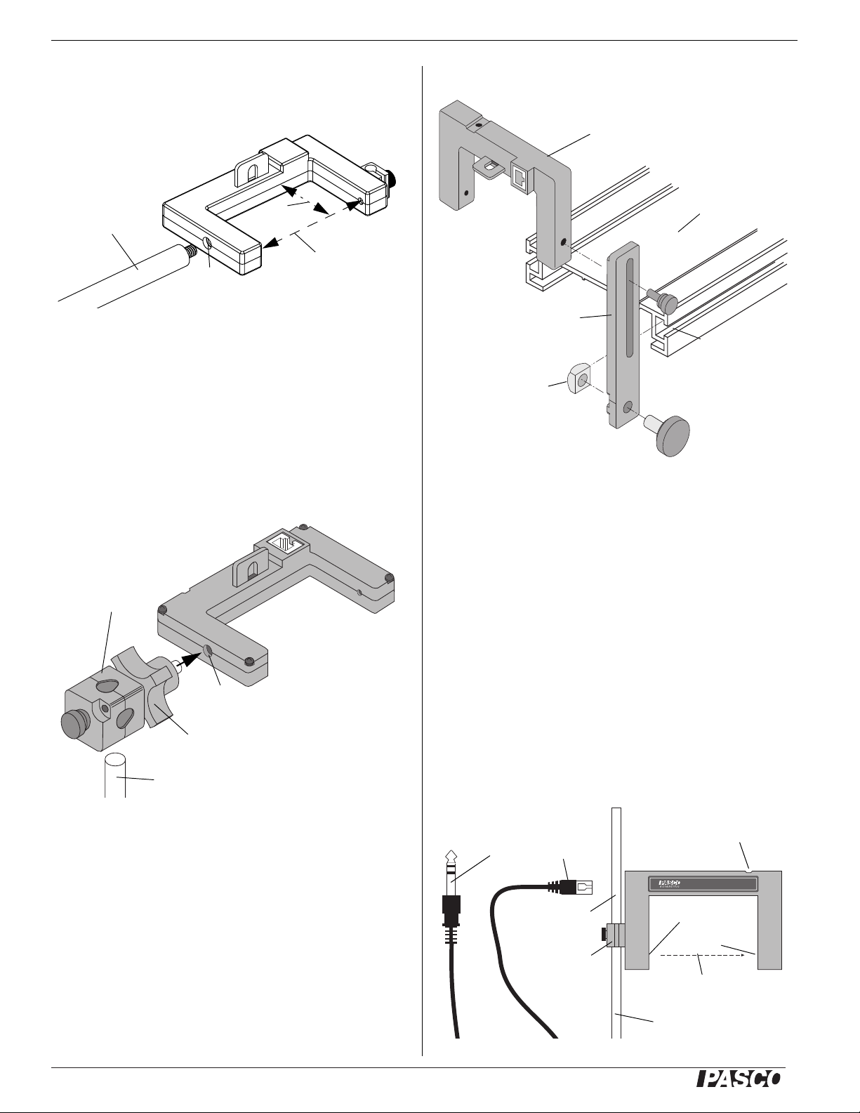
The small rod clamp and
thumbscrew allows the
Photogate Head to be
mounted on a 6.3 millimeter (1/4 in) diameter
support rod (e.g., PASCO
ME-9805 Photogate
Stand).
Support Rod
(from ME-9805)
1/4-20
thumbscrew
Small Rod Clamp
Photogate Cable
The Pulley Mounting Rod,
Photogate Head, Super
Pulley, and 1/4-20 Thumbscrew are in the ME-6838
Photogate/Pulley System.
ME-9498A
Instruction Sheet
012-06372B
*012-06372*
Introduction
The PASCO ME-9498A Photogate Head has a narrow infrared
beam and a fast fall time that provide very accurate signals for
timing. When the infrared beam between the source and detector is blocked, the output voltage of the photogate is low, and
the red LED (light emitting diode) on the photogate goes on.
When the beam is not blocked, the output voltage is high, and
the LED is off.
The cable included with the Photogate Head is detachable from
the unit. One end of the cable is a RJ12 telephone plug that connects to the RJ12 jack in the photogate housing. At the other
end, a stereo phone plug connects directly into a PASCO Photogate Timer (ME-9206B and ME-9215B), PASCO Smart Timer
(ME-8930), or into any PASCO interface with digital channels
or a PASPORT Digital Adapter (PS-2159). See the PASCO web
site at www.pasco.com for more information.
Additional Features
The raised slot on the housing provides a seat for attaching a
PASCO ME-9450A Super Pulley using a PASCO SA-9242 Pulley Mounting Rod or a 1/4-20 0.375 inch thumbscrew.
800-772-8700 www.pasco.com
Page 2
®
Photogate Head ME-9498A
Pulley
Mounting Rod
(SA-9242)
1/4-20
Threaded Hole
Width = 7.5 cm
Depth =
4.2 cm
Adjustable Angle Clamp
(ME-8744)
Support Rod (up to 12.7 mm diameter)
1/4-20
Threaded Hole
Locking Knob
PASCO Track
Photogate Bracket
(ME-9806)
T- s l o t
Photogate Head
Square
Nut
®
PHOTOGATE HEAD
ASSEMBLY NO.003-06268
LED is on when
beam is blocked
Infrared Beam
Small Rod
Clamp
RJ12
Phone Plug
Stereo
Phone Plug
Photogate Stand
(ME-9805)
6.2 mm (1/4 in)
diameter rod
Source
Detector
The Photogate Head can be attached to the PASCO SA-9242
Pulley Mounting Rod. This 14 cm long (6 in) by 9.5 mm (3/8 in)
diameter rod fits into the 1/4-20 threaded hole in the photogate
housing opposite the side of the small rod clamp..
The open space for the Photogate Head is 7.5 cm wide and 4.2
cm deep.
The Photogate Head can be mounted on a support rod of up to
12.7 millimeter (1/2 in) in diameter by attaching a PASCO
ME-8744 Adjustable Angle Clamp. It is necessary to remove
the “"mobile" part of the adjustable angle clamp from the clamp
assembly and secure the “fixed” part of the clamp assembly to
the 1/4-20 threaded hole in the photogate housing opposite the
side of the small rod clamp. Rotate the equipment to the correct
orientation and then secure it with the locking knob on the
clamp assembly.
Use the short thumbscrew from the bracket assembly for attaching the photogate to the mounting bracket.
Operation
1. Attach the Photogate Head to a support rod, clamp, or
mounting bracket.
The Photogate Head can also be attached to the side of a
PASCO Track with a ME-9806 Photogate Bracket (set of 2).
Slide the square nut on the Photogate Bracket into the T-slot on
the side of the PASCO Track. It is necessary to remove the small
rod clamp from the Photogate Head. (Save the clamp assembly
for later use.)
2
2. Position the photogate so the object to be timed will pass
through the photogate, blocking the infrared beam. To minimize parallax error, pass the object as close to the infrared
detector as possible, with the line of travel perpendicular to
the beam. Loosen the small rod clamp thumbscrew to
change the angle or height of the photogate.
3. Plug the RJ12 phone plug from the cable assembly into the
modular phone jack on the photogate housing.
4. Plug the stereo phone plug at the other end of the cable
assembly into the timer, adapter, or interface.
5. Test the operation of the photogate by watching the LED on
the photogate as the beam is blocked.
Page 3

®
Photogate Head ME-9498A
Experiments
Refer to the experiment guide that comes with your PASCO
equipment (e.g., Introductory Dynamics System).
Photogate Specifications
Photogate Width and Depth: 7.5 by 4.2 cm
Detector rise time: < 500 nanoseconds (ns)
Detector fall time: < 50 ns
Timing Resolution: 0.1 milliseconds
Parallax error: For an object passing within 1 centimeter (cm)
of the detector, with a velocity less than 10 m/s, the difference
between the true and effective length is less than 1 mm.
Power requirements: 5 VDC ± 5% at 45 mA
Infrared source: Peak at 880 nm
Additional Equipment Available:
• ME-9204B Accessory Photogate (includes ME-9498A
Photogate Head and ME-9805 Photogate Stand)
• ME-9805 Photogate Stand (includes base and 6.3 mm
(1/4 in) diameter support rod)
• ME-9806 Photogate Brackets (set of 2) for PASCO
Tracks
• ME-6821A Photogate Mounting Bracket for PASCO
Projectile Launchers
Technical Support
For assistance with any PASCO product, contact PASCO at:
Address: PASCO scientific
10101 Foothills Blvd.
Roseville, CA 95747-7100
Phone: 916-786-3800 (worldwide)
800-772-8700 (U.S.)
Fax: (916) 786-7565
Web: www.pasco.com
Email: support@pasco.com
For more information about the Photogate Head and the latest
revision of this Instruction Sheet, visit:
www.pasco.com/go?ME-9498A
Limited Warranty For a description of the product warranty, see the
PASCO catalog.
Copyright The PASCO scientific 012-06372B Photogate Head Instruc-
tion Sheet is copyrighted with all rights reserved. Permission is granted
to non-profit educational institutions for reproduction of any part of this
manual, providing the reproductions are used only in their laboratories
and classrooms, and are not sold for profit. Reproduction under any
other circumstances, without the written consent of PASCO scientific, is
prohibited.
Trademarks PASCO and PASCO scientific are trademarks or registered trademarks of PASCO scientific, in the United States and/or in
other countries. All other brands, products, or service names are or may
be trademarks or service marks of, and are used to identify, products or
services of, their respective owners. For more information visit
www.pasco.com/legal.
• ME-9450A Super Pulley*
• SE-9242 Pulley Mounting Rod*
• ME-9355 Base and Support Rod (includes tripod base
and 12.7 mm (1/2 in) diameter 45 cm long support rod)
• ME-9377 Picket Fence
• ME-8744 Adjustable Angle Clamp
• ME-8752 Photogate Pendulum Set (includes four different pendula)
• ME-6664 Photogate Tape Set (includes flexible picket
fence tape and tape guide)
*Included in the ME-6838 Photogate/Pulley System along with a Photogate Head and 1/4-20 Thumbscrew
See the PASCO catalog or web site at www.pasco.com for more information about the Photogate Head. For example, you can download instruction manuals for the Accessory Photogate, Picket Fence, Photogate
Pendulum Set, and Photogate Tape Set.
3
 Loading...