

Page 1
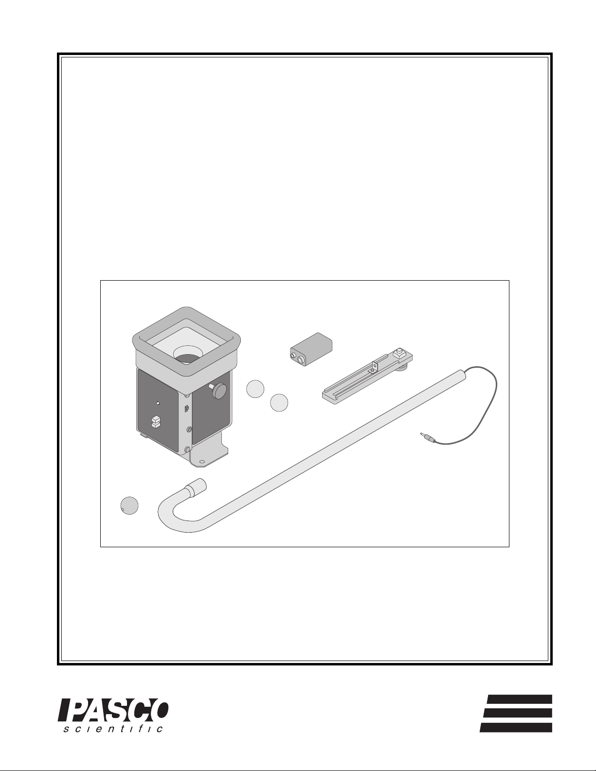
Instruction Manual and
Experiment Guide for
the PASCO scientific
Model ME-9486
BALLISTIC CART
ACCESSORY
012-05460A
7/94
CAUTION!
DO NOT LOOK
DOWN BARREL
ON WHEN
FLASHING
BALL LAUNCHER
PHOTOGATE
BALLISTIC CART
ACCESSORY
ON
POWER
OFF
DROP ROD JACK
© 1994 PASCO scientific $5.00
10101 Foothills Blvd. • P.O. Box 619011 • Roseville, CA 95678-9011 USA
Phone (916) 786-3800 • FAX (916) 786-8905 • TWX 910-383-2040
better
ways to
teach physics
Page 2

Page 3

012-05460A Ballisitic Cart Accessory
T able of Contents
Section Page
Copyright, Warranty, and Equipment Return .....................................................ii
Introduction ......................................................................................................1
Equipment ........................................................................................................2
Assembly
ME-9486 Ballistic Cart Accessory .............................................................. 3
ME-9487 Drop Rod Accessory ...................................................................4
Experiments
Experiment 1: Shoot and Catch - Demonstration.....................................5
Experiment 2: Tunnel - Demonstration ...................................................7
Experiment 3: Accelerating Cart - Demonstration ...................................9
Experiment 4: Inclined Plane - Demonstration ....................................... 11
Experiment 5: Drop Ball - Demonstration..............................................13
Experiment 6: Accelerating Cart - Demonstration ..................................15
Experiment 7: Inclined Plane - Demonstration ....................................... 17
Experiment 8: Bombing Run - Demonstration .......................................19
Experiment 9: Bombing Run (Computerized) ........................................21
Experiment 10: Bombing Run (Non-Computerized) .............................. 25
Teacher’s Guide............................................................................................... 28
Technical Support ................................................................................... Back Cover
i
Page 4

Ballistic Cart Accessory 012-05460A
Copyright, Warranty and Equipment Return
Please—Feel free to duplicate this manual
subject to the copyright restrictions below.
Copyright Notice
The PASCO scientific Model ME-9486 Ballistic Cart
Accessory manual is copyrighted and all rights reserved.
However, permission is granted to non-profit educational
institutions for reproduction of any part of this manual
providing the reproductions are used only for their
laboratories and are not sold for profit. Reproduction
under any other circumstances, without the written
consent of PASCO scientific, is prohibited.
Limited Warranty
PASCO scientific warrants this product to be free from
defects in materials and workmanship for a period of one
year from the date of shipment to the customer. PASCO
will repair or replace, at its option, any part of the product
which is deemed to be defective in material or workmanship. This warranty does not cover damage to the product
caused by abuse or improper use. Determination of
whether a product failure is the result of a manufacturing
defect or improper use by the customer shall be made
solely by PASCO scientific. Responsibility for the return
of equipment for warranty repair belongs to the customer.
Equipment must be properly packed to prevent damage
and shipped postage or freight prepaid. (Damage caused
by improper packing of the equipment for return shipment will not be covered by the warranty.) Shipping
costs for returning the equipment, after repair, will be
paid by PASCO scientific.
Equipment Return
Should this product have to be returned to PASCO
scientific, for whatever reason, notify PASCO scientific
by letter or phone BEFORE returning the product. Upon
notification, the return authorization and shipping instructions will be promptly issued.
➤ NOTE:
NO EQUIPMENT WILL BE ACCEPTED FOR
RETURN WITHOUT AN AUTHORIZATION.
When returning equipment for repair, the units must be
packed properly. Carriers will not accept responsibility
for damage caused by improper packing. To be certain
the unit will not be damaged in shipment, observe the
following rules:
➀ The carton must be strong enough for the item
shipped.
➁ Make certain there is at least two inches of packing
material between any point on the apparatus and the
inside walls of the carton.
➂ Make certain that the packing material can not shift in
the box, or become compressed, thus letting the instrument come in contact with the edge of the box.
Address: PASCO scientific
10101 Foothills Blvd.
Credits
This manual authored by: Jon Hanks and Eric Ayars
P.O. Box 619011
Roseville, CA 95678-9011
Phone: (916) 786-3800
FAX: (916) 786-8905
ii
Page 5
012-05460A Ballistic Cart Accessory
Introduction
The PASCO ME-9486 Ballistic Cart Accessory is used
with the PASCO Dynamics Cart and track (ME-9429A or
ME-9452) to shoot a plastic ball straight up from the
moving cart. If the cart is moving at a constant velocity,
the ball will fall back into the catcher on the cart. The ball
is released using a photogate so there is no impulse given
to the cart upon release as there is in other models which
used a string to release the ball. The barrel can be aimed
to ensure that the ball is shot vertically. Special nobounce foam prevents the ball from bouncing back out of
the catcher cup.
The PASCO ME-9487 Drop Rod Accessory can be
mounted to the Ballistic Cart Accessory so a special plastic ball can be dropped from rest (relative to the cart)
above the moving cart. Also the drop rod can be rotated
away from the cart so the ball will drop onto the floor to
perform bombing runs.
➤ NOTE: It is better to use a 2.2 m track (ME-
9452) rather than the 1.2 m track (ME-9429A) because it gives you more room to work.
1
Page 6
Ballistic Cart Accessory 012-05460A
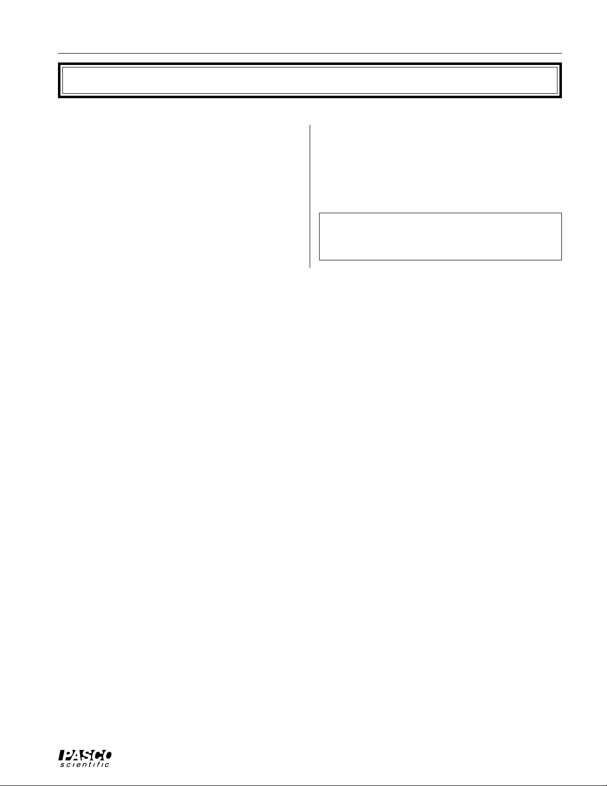
Equipment
Ballistic Cart
Accessory
9-volt
battery
Trip Bracket
CAUTION!
DO NOT LOOK
DOWN BARREL
ON WHEN
FLASHING
BALL LAUNCHER
PHOTOGATE
ON
OFF
yellow nylon
balls (2)
POWER
assembly
BALLISTIC CART
ACCESSORY
DROP ROD JACK
thumbscrews (2)
ME-9486 Ballistic Cart accessory Equipment
The ME-9486 Ballistic Cart Accessory includes the
following:
• one Ballistic Cart Accessory
• one Trip Bracket assembly
• one 9-volt battery
modified pink
nylon balls (2)
• two yellow nylon balls
• two thumbscrews
Drop Rod
Accessory
ME-9487 Drop Rod Accessory Equipmemt
The ME-9487 Drop Rod Accessory includes the
following:
• oneDrop Rod Accessory
• two modified pink nylon balls
2
Page 7
012-05460A Ballistic Cart Accessory
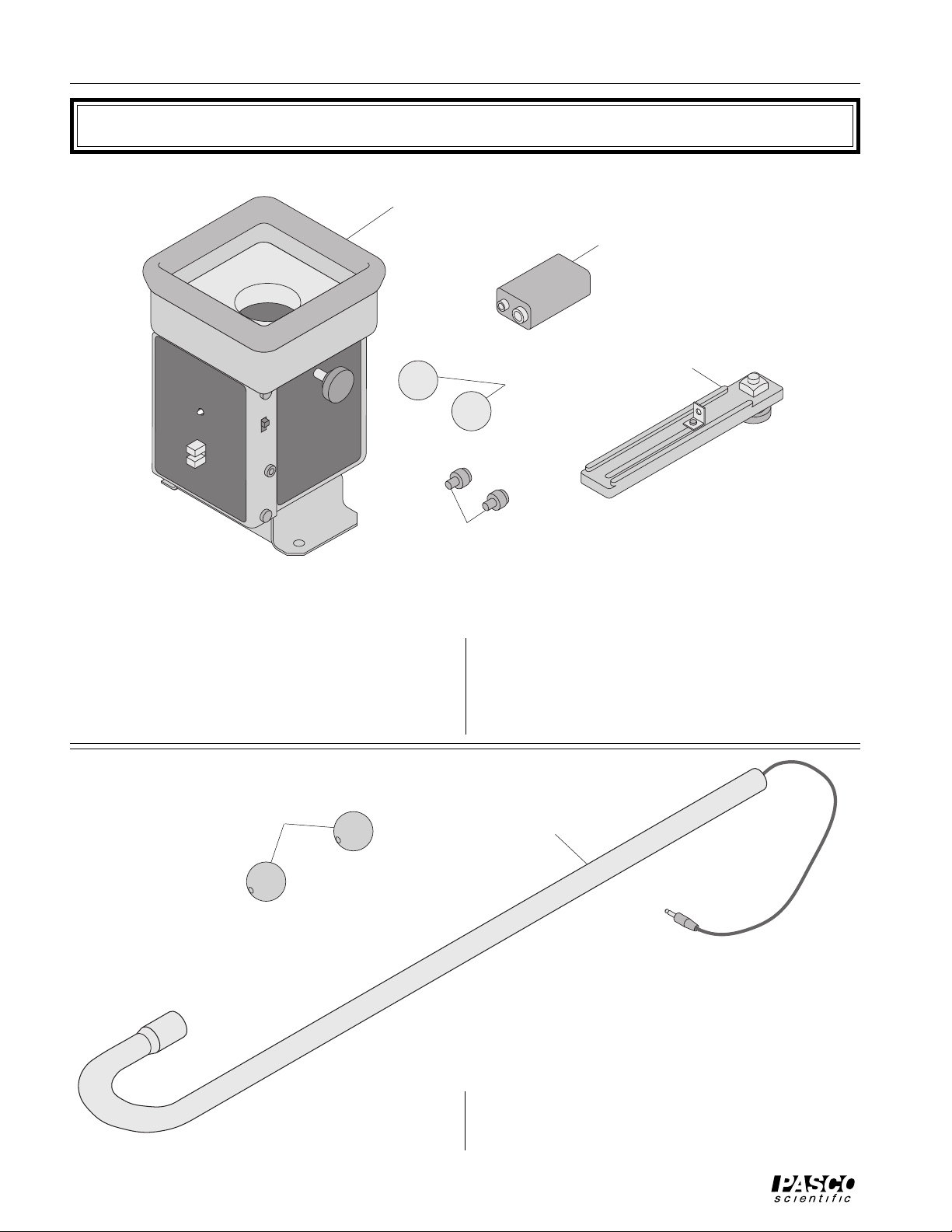
Assembly
ME-9486 Ballistic Cart Accessory
Battery Installation
➀ Turn the unit on its side and install the 9-volt battery
in the bottom of the unit. See Figure 1.
“ON” LED
battery
holder
bottom of
unit
Figure 1: Battery Installation
Attaching the Ballistic Cart Accessory to a Dynamics
Cart
➀ Remove the two mounting screws (see Figure 2) from
their storage place on the side of the unit. (There are
two extra screws included with the Ballistic Cart Accessory.) Use these screws to attach the Ballistic Cart
Accessory to the mass tray of the dynamics cart.
Ballistic Cart
Accessory
thumbscrew
storage
power
switch
AIM ADJUST
Drop Rod
jack
DROP ROD JACK
AIM ADJUST
DROP ROD CLAMP
aim adjust
screws
thumbscrews
(2)
Dynamics Cart
Figure 2: Ballistic Cart Installation
➁ Slide the photogate trip bracket into the T-slot on the
dynamics track. See Figure 3.
Ballistic Cart
Accessory
nylon
thumbscrew
bracket
thumbscrew
square nut
bracket
“L” bracket
dynamics cart
track
ball launcher
photogate
assembled
trip bracket
Figure 3: Using the Trip Bracket
3
DYNAMICS
CART
ON
POWER
OFF
INSTRUCTIONS
1. MOUNT UNIT ON CART.
2. TURN UNIT ON.
3. INSERT AND DEPRESS BALL.
4. INTERRUPT PHOTOGATE TO LAUNCH
BALL.
DROP ROD JACK
TURN UNIT OFF WHEN NOT IN USE
9V BATTERY LOCATED UNDER
MOUNTING BRACKET
ME-9430
AIM ADJUST
FORWARD - BACK
PASCO
scientific
Dynamics
Cart
Page 8

Ballistic Cart Accessory 012-05460A
Setting Up the Ballistic Cart Accessory
➀ Move the aim adjusting screws (see Figure 2) in and
out to check that the barrel moves freely. Do this by
looking down the barrel while adjusting the screws. If
the barrel sticks it is because the foam catches it. To
remedy this, gently lift up slightly on the edges of the
foam to unstick it from the barrel.
➁ Level the dynamics track. To check if the track is
level, place the cart on the track and give it a small
push in one direction. Then push it in the opposite direction to see if the cart rolls easier in one direction
than the other. Also make the track level from side-toside by placing the plastic ball at rest on the track to
see if it rolls one way or the other.
ME-9487 Drop Rod Accessory
Drop Rod Installation
➀ Use the 1
clamp to the side of the Ballistic Cart Accessory. See
Figure 4. Screw the thumb screw into the end of the
drop rod clamp.
1
/2 inch metal screws to fasten the drop rod
➂ With the cart at rest on the level track, adjust the aim
adjust screws until the ball shoots straight up and
lands back in the catcher cup. Use a penny or dime to
trip the photogate when the cart is at rest. Remember,
the power switch must be turned on before the trip
switch will operate. The LED will blink while the
power is on. Also remember to turn the power switch
off before storing the accessory.
➤ NOTE: The trip switch must be mounted on the
same side as the photogate on the Ballistic Cart. See
Figure 3.
➁ Thread the cord from the drop rod through the drop
rod clamp and clamp the end of the drop rod by tightening the thumb screw.
➤ CAUTION: Do not over-tighten the screw or
the tube may be crushed.
Ballistic Cart
Accessory
drop rod
jack
AIM ADJUST
AIM ADJUST
DROP ROD JACK
drop rod cord
Figure 4: Drop Rod Installation.
DROP ROD CLAMP
thumbscrew
drop rod
1 1/2 inch
metal
mounting
screws (2)
nylon
➂ Plug the drop rod cord into the drop rod jack on the
side of the Ballistic Cart Accessory.
➤ NOTE: Plugging this cord in disables the
launching mechanism of the Ballistic Cart Accessory so when you want to use the launcher you
must unplug the drop rod accessory.
➃ Note that the Drop Rod Accessory requires a special
ball that has an iron
insert. The balls for
the Drop Rod Accessory and the Ballistic Cart Accessory are different
colors so they can
be easily distinguished. To hang
the ball from the
drop rod, the pin on
the drop rod must
be inserted into the
small hole in the
ball. See Figure 5.
drop rod
pin
modified pink
ball
Figure 5: Ball and Drop Rod
4
Page 9

012-05460A Ballistic Cart Accessory
Experiment 1: Shoot and Catch - Demonstration
EQUIPMENT NEEDED
– Ballistic Cart Accessory (ME-9486)
– Dynamics Cart and track (ME-9452)
Purpose
This demonstration shows that when the ball is shot vertically upward from the cart while the
cart is moving at any constant speed, the ball will land back in the cart.
Procedure
➀ Prior to the beginning of the demonstration, perform the Setup procedure.
➁ With the cart at rest on the track, load the ball and trip the release mechanism with a penny or
other opaque object. This proves to the students that the ball is being launched straight up.
➂ Put the photogate trip bracket near one end of the track, leaving enough room to push the cart up
to its maximum speed before it reaches the trip bracket. See Figure 1.1. Load the ball and start
the cart from that end of the track by giving the cart a gentle push. The cart will move slowly and
the ball will be caught.
➃ Return the cart to the end of the track. Load the ball and give the cart a stronger push.
➤ CAUTION! You must catch the cart with your hand before the cart reaches the end stop on
the track because the cart will derail when it’s moving fast. The ball will be caught at any cart
speed.
➤ NOTE: If you have the Drop Rod Accessory, try putting it on the Ballistic Cart Accessory to
act as a reference line. With this reference line, the ball appears to go straight up and down.
Without the reference, the ball may appear to go in a parabola.
trip bracket
end stop
ball launcher
photogate
Figure 1.1: Setup for Shoot and Catch
5
Page 10

Ballistic Cart Accessory 012-05460A
Notes:
6
Page 11
012-05460A Ballistic Cart Accessory
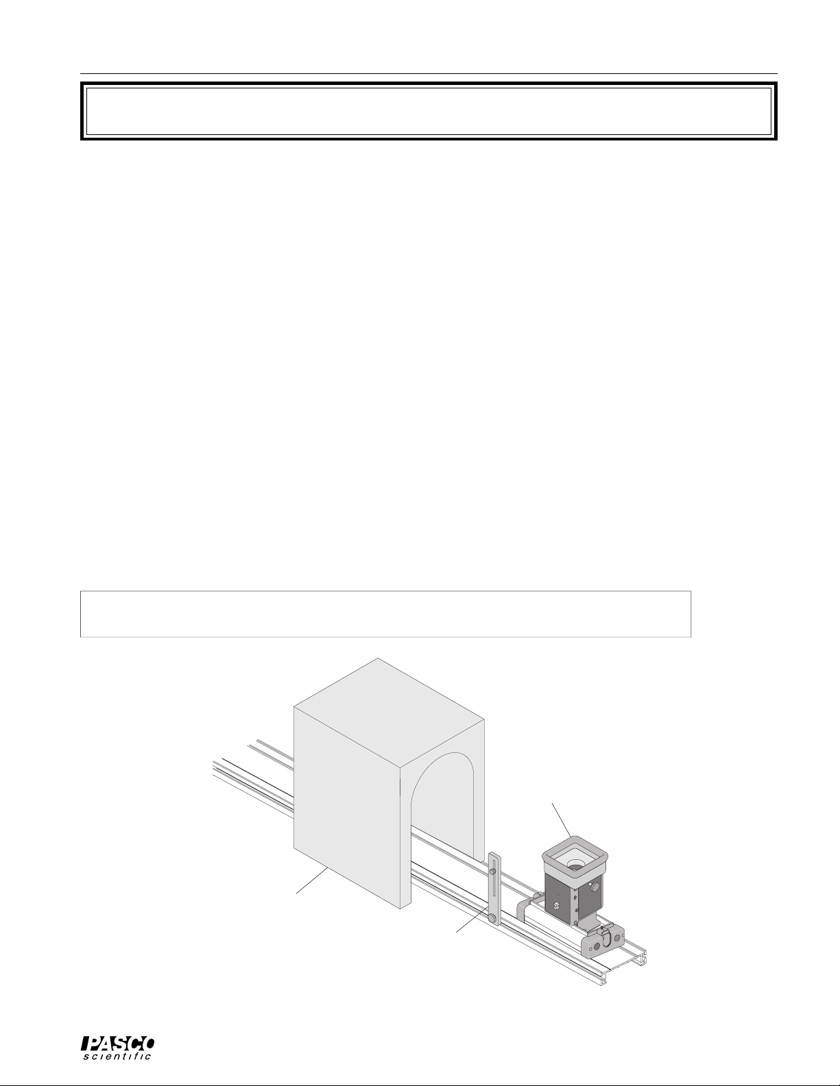
Experiment 2: Tunnel - Demonstration
EQUIPMENT NEEDED
– Ballistic Cart Accessory (ME-9486)
– Dynamics Cart and track
– Cardboard box (33 cm {13"} cube) for tunnel (construction details given below)
Purpose
This demonstration shows that the ball can be caught by the cart even if the cart passes through a
tunnel while the ball is in the air. The tunnel accentuates the parabolic path of the ball.
Procedure
➀ Prior to the beginning of the demonstration, perform the Setup procedure.
➁ Construct a tunnel from a cardboard box: Cut the flaps off two opposing ends of the box. Cut a
15 cm wide, 27 cm high hole in these two opposing ends of the box. See Figure 2.1.
➂ Set the box upside-down over the middle of the dynamics track. Check the clearance by running
the cart through the tunnel.
➃ Position the photogate trip bracket in front of the tunnel so the ball will be launched just before
the cart enters the tunnel.
➄ Load the ball and push the cart toward the tunnel. You may have to practice to get the right
speed so the cart will make it through the tunnel before the ball comes down.
➤ CAUTION! You must catch the cart with your hand before the cart reaches the end stop on
the track because the cart will derail when it’s moving fast.
Ballistic Cart
Accessory
tunnel
trip bracket
Figure 2.1: Tunnel
7
CAUTION!
DO NOT LOOK
DOWN BARREL
ON WHEN
FLASHING
BALL LAUNCHER
PHOTOGATE
BALLISTIC CART
ACCESSORY
ON
POWER
OFF
DROP ROD JACK
Page 12

Ballistic Cart Accessory 012-05460A
Notes:
8
Page 13

012-05460A Ballistic Cart Accessory
Experiment 3: Accelerating Cart - Demonstration
EQUIPMENT NEEDED
– Ballistic Cart Accessory (ME-9486)
– Dynamics Cart and track
– String
– Clamp-on pulley
– 50 gram mass and mass hanger
Purpose
This demonstration shows that when the ball is shot vertically upward from the cart while the
cart is accelerating, the ball will not land in the cart.
Procedure
➀ Prior to the beginning of the demonstration, perform the Setup procedure.
➁ Clamp the pulley to the end of the track. Attach a string (about 1 meter long) to the cart and pass
it over the pulley. Hang about 50 grams on the string. See Figure 3.1.
➂ Put the photogate trip bracket in a position where it will launch the ball after the cart has begun
to move.
➃ Start the cart as far back as possible, load the ball, and let it go. In this case, the ball will fall
behind the cart.
➤ CAUTION! You must catch the cart with your hand before the cart reaches the end stop on
the track because the cart will derail when it’s moving fast.
pulley
50g
end stop
string
table
Figure 3.1: Accelerating Cart.
trip bracket
9
Page 14

Ballistic Cart Accessory 012-05460A
Notes:
10
Page 15

012-05460A Ballistic Cart Accessory
Experiment 4: Inclined Plane - Demonstration
EQUIPMENT NEEDED
– Ballistic Cart Accessory (ME-9486)
– Dynamics Cart and track
– Table clamp and rod
– Rod clamp for dynamics track
Purpose
This demonstration shows that a ball launched from a cart that is accelerating down an inclined
plane will be caught by the cart regardless of the angle of incline.
Procedure
➀ Prior to the beginning of the demonstration, perform the Setup procedure.
➁ Incline the track using the table clamp and rod. See Figure 4.1. Be careful not to choose too high
an angle because the cart will reach such a high speed that it will crash at the bottom. For any
angle you choose, be sure you catch the cart at the bottom to keep it from derailing and crashing
to the floor.
➂ Put the photogate trip bracket in a position where it will launch the ball after the cart has begun
to move.
➃ Start the cart at the top of the incline, load the ball, and release the cart. The ball will land in the
cart.
➤ CAUTION! Remember to catch the cart!
➄ Repeat the demonstration for a different angle.
➅ Start the cart at the bottom of the incline. Give the
cart a push uphill so that it travels past the trip
bracket.
trip bracket
end stop
rod clamp
table clamp
Figure 4.1: Inclined Plane
11
Page 16

Ballistic Cart Accessory 012-05460A
Notes:
12
Page 17

012-05460A Ballistic Cart Accessory
Experiment 5: Drop Ball - Demonstration
EQUIPMENT NEEDED
– Ballistic Cart Accessory (ME-9486)
– Dynamics Cart and track
– Drop Rod Accessory (ME-9487)
Purpose
The purpose of this demonstration is to show that when the ball is dropped from the drop rod
while the cart is moving at any constant speed, the ball will land in the cart.
Procedure
➀ Prior to the beginning of the demonstration, perform the Setup procedure.
➁ Position the drop rod so that the ball will be directly over the cup. See Figure 5.1.
➂ With the cart at rest on the track, hang the ball on the drop rod and trip the release mechanism
with a penny or other opaque object. This shows the students that the ball is drops straight down
and is caught by the cart.
➃ Put the photogate trip bracket near one end of the track, leaving enough room to push the cart up
to its maximum speed before it reaches the trip bracket. Hang the ball from the drop rod and give
the cart a gentle push.
➄ Return the cart to the end of the track. Hang the ball from the drop rod and give the cart a stron-
ger push. The ball will be caught at any cart speed.
➤ CAUTION! You must catch the cart with your
hand before the cart reaches the end stop on the
track because the cart will derail when it’s moving
fast.
trip bracket
end stop
modified
pink ball
Drop Rod
Accessory
Figure 5.1: Setup for Drop Ball
13
Page 18

Ballistic Cart Accessory 012-05460A
Notes:
14
Page 19

012-05460A Ballistic Cart Accessory
Experiment 6: Accelerating Cart - Demonstration
EQUIPMENT NEEDED
– Ballistic Cart Accessory (ME-9486)
– Dynamics Cart and track
– Drop Rod Accessory (ME-9487)
– String
– Clamp-on pulley
– 50 gram mass and mass hanger
Purpose
This demonstration shows that when the ball is dropped from the drop rod on a cart that is accelerating, the ball will not land in the cart.
Procedure
➀ Prior to the beginning of the demonstration, perform the Setup procedure.
➁ Position the drop rod so that the ball will be directly over the cup.
➂ Clamp the pulley to the end of the track. Attach a string (about 1 meter long) to the cart and pass
it over the pulley. Hang about 50 grams on the string. See Figure 6.1.
➃ Put the photogate trip bracket in a position where it
will drop the ball after the cart has begun to move.
➄ Start the cart as far back as possible, hang the ball
on the drop rod, and release the cart. In this case,
the ball will fall behind the cart.
modified
pink ball
Drop Rod
Accessory
➤ CAUTION! You must catch the cart with your
hand before the cart reaches the end stop on the
track because the cart will derail when it’s moving
fast.
pulley
end stop
string
trip bracket
50g
table
Figure 6.1: Accelerating Cart
15
Page 20

Ballistic Cart Accessory 012-05460A
Notes:
16
Page 21

012-05460A Ballistic Cart Accessory
Experiment 7: Inclined Plane - Demonstration
EQUIPMENT NEEDED
– Ballistic Cart Accessory (ME-9486)
– Dynamics Cart and track
– Drop Rod Accessory (ME-9487)
– Table clamp and rod
– Rod clamp for dynamics track
Purpose
This demonstration shows that a ball dropped from the drop rod on a cart that is accelerating
down an inclined plane will be caught by the cart regardless of the angle of incline.
Procedure
➀ Prior to the beginning of the demonstration, perform the Setup procedure.
➁ Position the drop rod so that when the track is level, the ball will be directly over the cup.
end stop
trip bracket
modified
pink ball
Drop Rod
Accessory
rod clamp
table clamp
table
Figure 7.1: Inclined Plane
17
Page 22

Ballistic Cart Accessory 012-05460A
➂ Incline the track (see Figure 7.1) using the table clamp and rod. Be careful not to choose too high
an angle because the cart will reach such a high speed that it will crash at the bottom. For any
angle you choose, be sure you catch the cart at the bottom to keep it from derailing and crashing
to the floor.
➃ Put the photogate trip bracket in a position where it will drop the ball after the cart has begun to
move.
➄ Start the cart at the top of the incline, hang the ball on the drop rod, and release the cart. The ball
will land in the cart.
➤ CAUTION! Remember to catch the cart!
➅ Repeat the demonstration for a different angle.
18
Page 23

012-05460A Ballistic Cart Accessory
Experiment 8: Bombing Run - Demonstration
EQUIPMENT NEEDED
– Ballistic Cart Accessory (ME-9486)
– Dynamics Cart and track
– Drop Rod Accessory (ME-9487)
– Paper cup (for catching ball)
Purpose
This demonstration shows the students that a bomber must release the bomb before the plane is
over the target.
Procedure
➀ Prior to the beginning of the demonstration, perform the Setup procedure.
end stop
table
trip bracket
modified
pink ball
Drop Rod
Accessory
cup
Figure 8.1: Bombing Run
19
floor
Page 24

Ballistic Cart Accessory 012-05460A
➁ Align the track with the edge of the table.
➂ Position the drop rod so that as the ball drops, it will miss the table and fall to the floor.
➃ Position the photogate trip bracket near the middle of the track.
➄ Place the cart on the track at the position of the trip bracket and place the cup on the floor under
the drop rod. Pull the cart back to one end of the track, hang the ball on the drop rod, and push the
cart. The ball will be dropped at the moment the cart passes over the cup. See Figure 8.1.
➅ Discuss with the students the reason the ball misses the cup.
➆ Move the trip bracket back and try it again.
20
Page 25

012-05460A Ballistic Cart Accessory
Experiment 9: Bombing Run (Computerized)
EQUIPMENT NEEDED
– Ballistic Cart Accessory (ME-9486) – 200-gram mass and mass hanger
– Dynamics Cart and 2.2 m track (ME-9452) – Photogate and photogate bracket
– Drop Rod Accessory (ME-9487) – Computer
– Paper cup (for catching ball) – Plumb bob
– Physics string (SE-8050) (NOTE: Stiff string is required.) – Meter stick
– Clamp-on pulley
Purpose
In this experiment, the distance from the target that a bomber must release the bomb is calculated
and verified.
Procedure
➀ Prior to the beginning of the experiment, perform the Setup procedure.
➁ Align the track with the edge of the table.
➂ Position the drop rod so that as the ball drops, it will miss the table and fall to the floor.
➃ Position the photogate trip bracket near the middle of the track.
Drop Rod
Accessory
modified
pink ball
photogate
trip bracket
string
pulley
photogate
bracket
end stop
end stop
table
Figure 9.1: Smart Pulley Setup for Bombing Run
21
Page 26

Ballistic Cart Accessory 012-05460A
➄ Clamp the pulley on the end of the track. Position the photogate and its bracket over the clamp-on
pulley so it acts as a Smart Pulley. See Figure 9.1.
➅ Tie one end of a 2.2-meter long string to the cart and pass the other end over the pulley and hang
about 200 g on it.
➤ NOTE: the string must be long enough so the cart can reach the end stop furthest from the
pulley. The end stop will mark the position where the cart will be started from rest each time.
➆ Move the cart toward the pulley until the mass just touches the floor. Then place the trip bracket
at the cart’s position. This will cause the cart to drop the ball after the cart has reached its constant
speed. Note that the stiff string will continue to move forward and not bunch up under the cart.
This is the reason for not using thread.
➇ Without hanging the ball on the drop rod, pull the cart back against the end stop and release it
from rest. Record data with the computer and determine the maximum speed, v, of the cart.
Drop Rod
Accessory
end stop
cup
modified
pink ball
trip bracket
end stop
y
table
floor
x
Figure 9.2: Projectile Motion For Bombing Run.
22
Page 27

012-05460A Ballistic Cart Accessory
y
1
t
➤ NOTE: It is also possible to determine the speed using conservation of energy without a com-
puter. You would need to know the mass of the Ballistic Cart Accessory and measure the
distance the hanging mass falls.
➈ Hang the ball on the drop rod and measure the distance, y, from the bottom of the ball down to
the floor. See Figure 9.2.
➉ The vertical distance, y, that the ball falls is given by
=
Using your measured value for y, calculate the time it takes for the ball to fall.
=
Calculate the horizontal distance, x, that the ball travels.
11
x = vt
This is the position where the ball should land.
Use a plumb bob and meter stick to measure off the distance, x. Place a paper cup at this position
12
on the floor.
Hang the ball from the drop rod, pull the cart back against the end stop and release it from rest.
13
Observe whether or not the ball goes into the cup.
2
gt
2
2y
g
Questions
➀ Did the ball land in the cup? If not, why not?
➁ What are some of the possible sources of error in this experiment that would cause the ball to
miss?
23
Page 28

Ballistic Cart Accessory 012-05460A
Notes:
24
Page 29

012-05460A Ballistic Cart Accessory
x
t
x
a
m+M
Experiment 10: Bombing Run
(Non-Computerized)
EQUIPMENT NEEDED
– Ballistic Cart Accessory (ME-9486) – Clamp-on pulley
– Dynamics Cart and track (ME-9452) – 50-200g mass and hanger
– Drop Rod Accessory (ME-9487) – Scale
– Paper cup (for catching ball) – Plumb bob
– String – Meter stick
Purpose
In this experiment, the distance from the target that a bomber must release the bomb is calculated
and verified. Instead of using a constant-velocity cart, we will use a known acceleration for a
known distance to obtain a repeatable velocity at the time of release.
Theory
We can measure the distance that the cart will accelerate before dropping the ball (d in Figure
10.1) and the height y that the ball will fall. Knowing the mass of the cart and the hanging mass,
we can predict where the ball will land.
First, the velocity of the cart after travelling a distance d from rest will be
vo=2ad
where a is the acceleration of the system. The horizontal distance x that the ball will travel during its fall will be
= vot
y
where ty is the time it takes for the ball to fall:
2y
=
y
Combining these terms gives us:
=2ad
2y
g
g
=2
ady
g
Now, the acceleration of the system is just
=
m
g
25
Page 30

Ballistic Cart Accessory 012-05460A
x
m+M
where m is the hanging mass and M is the mass of the cart and all attachments including the ball.
Substituting this value for acceleration into the equation for x gives us our desired equation:
end stop
=2
mdy
Drop Rod
Accessory
trip bracket
modified
pink ball
initial
position of
apparatus
y
mass
cup
table
floor
dx
Figure 9.2: Projectile Motion For Bombing Run.
Procedure
➀ Weigh the cart and its attachments. Record this mass as M. Weigh the hanging mass, and record it
as m.
➁ Set up the equipment as shown in Figure 10.1. You may want to tape a large sheet of paper to the
floor on which to mark positions.
26
Page 31

012-05460A Ballistic Cart Accessory
➂ Hold the cart in its initial position against the end stop. Hang the plumb bob from the ball release
point and mark the initial position. Slowly move the cart to where the trip bracket just causes the
ball to release, and use the plumb bob to mark this position. Measure the distance between these
positions and record as d.
➃ Calculate x. Measure this distance from the point at which the ball drops, and mark this location.
Place the paper cup on this mark.
➄ Hold the cart against the end stop. Make sure that the ball is loaded correctly and the Ballistic
Cart Accessory is turned on.
➆ Release the cart, and see if the ball lands in the cup.
Questions
➀ Did the ball land in the cup? If not, why not?
➁ What are some of the possible sources of error in this experiment that would cause the ball to
miss?
27
Page 32

Ballistic Cart Accessory 012-05460A
T eacher’s Guide
Experiments 4 and 7: Inclined Plane - Demonstration
Why the Ball is Still Caught in the Inclined
Plane Experiments
There have been enough questions about these two
experiments—including some from people who
should know better—that we thought it would be
best to explain exactly what was going on and why
the ball is still caught.
First, let’s consider the horizontal case:
Velocity Acceleration
The cart and the ball have the same horizontal
component of velocity. The vertical component of
the ball’s velocity does not affect the alignment of
the ball and cart, so the ball lands in the cart.
The horizontal component of the acceleration of
both cart and ball is the same: zero, which ensures
that the ball and cart remain aligned.
Now let’s consider the case where the cart is
accelerating:
In this case, the ball’s acceleration is still only in
the vertical plane, but the cart has a horizontal
acceleration. This horizontal acceleration changes
the velocity of the cart, but not the velocity of the
ball. The cart does not remain directly beneath the
ball and the ball is not caught.
When the track is tilted, things become a bit more
complicated; but if you break the vectors into their
components it becomes more clear:
The cart and the ball have the same component of
acceleration parallel to the track. Since they have
the same initial parallel-component velocity and the
same acceleration, they will thus always have the
same parallel-component velocity. The ball will
always be on a line with the cart perpendicular to
the track, and it will be caught.
Acceleration
28
Page 33

012-05460A Ballistic Cart Accessory
T echnical Support
Feed-Back
If you have any comments about this product or this
manual please let us know. If you have any suggestions on alternate experiments or find a problem in the
manual please tell us. PASCO appreciates any customer feed-back. Your input helps us evaluate and
improve our product.
To Reach PASCO
For Technical Support call us at 1-800-772-8700 (tollfree within the U.S.) or (916) 786-3800.
Contacting Technical Support
Before you call the PASCO Technical Support staff it
would be helpful to prepare the following information:
• If your problem is computer/software related, note:
Title and Revision Date of software.
Type of Computer (Make, Model, Speed).
Type of external Cables/Peripherals.
• If your problem is with the PASCO apparatus, note:
Title and Model number (usually listed on the label).
Approximate age of apparatus.
A detailed description of the problem/sequence of
events. (In case you can't call PASCO right away,
you won't lose valuable data.)
If possible, have the apparatus within reach when
calling. This makes descriptions of individual parts
much easier.
• If your problem relates to the instruction manual,
note:
Part number and Revision (listed by month and year
on the front cover).
Have the manual at hand to discuss your questions.
29
Page 34

 Loading...