

Page 1
Includes
Teacher's Notes
and
Typical
Experiment Results
Instruction Manual and
Experiment Guide for
012-03051F
3/95
the PASCO scientific
Model ME-9341
INTRODUCTORY
ROTATIONAL APPARATUS
© 1987 PASCO scientific $5.00
Page 2

Page 3

012-03051F Introductory Rotational Apparatus
T able of Contents
Section........................................................................................................Page
Copyright, Warranty and Equipment Return...................................................ii
Introduction .....................................................................................................1
Equipment........................................................................................................2
Setup .............................................................................................................4
Timing with a Photogate..................................................................................6
Five Copy-Ready Experiments:.......................................................................7
Experiment 1: Angular Acceleration—1..................................................9
Experiment 2: Angular Acceleration—2.................................................11
Experiment 3: Gravitational - Rotational Energy....................................15
Experiment 4: Frictional Torque .............................................................17
Experiment 5: Rotational Collisions........................................................19
Teacher's Guide ..............................................................................................23
Appendix ........................................................................................................33
Technical Support.................................................................................... back cover
i
Page 4

Introductory Rotational Apparatus 012-03051F
Copyright, Warranty and Equipment Return
Please—Feel free to duplicate this manual
subject to the copyright restrictions below.
Copyright Notice
The PASCO scientific Model ME-9341 Introductory
Rotational Apparatus manual is copyrighted and all rights
reserved. However, permission is granted to non-profit
educational institutions for reproduction of any part of
this manual providing the reproductions are used only for
their laboratories and are not sold for profit. Reproduction under any other circumstances, without the written
consent of PASCO scientific, is prohibited.
Limited Warranty
PASCO scientific warrants this product to be free from
defects in materials and workmanship for a period of one
year from the date of shipment to the customer. PASCO
will repair or replace, at its option, any part of the product
which is deemed to be defective in material or workmanship. This warranty does not cover damage to the product
caused by abuse or improper use. Determination of
whether a product failure is the result of a manufacturing
defect or improper use by the customer shall be made
solely by PASCO scientific. Responsibility for the return
of equipment for warranty repair belongs to the customer.
Equipment must be properly packed to prevent damage
and shipped postage or freight prepaid. (Damage caused
by improper packing of the equipment for return shipment will not be covered by the warranty.) Shipping
costs for returning the equipment, after repair, will be
paid by PASCO scientific.
Equipment Return
Should the product have to be returned to PASCO
scientific for any reason, notify PASCO scientific by
letter, phone, or fax BEFORE returning the product.
Upon notification, the return authorization and
shipping instructions will be promptly issued.
ä
NOTE: NO EQUIPMENT WILL BE
ACCEPTED FOR RETURN WITHOUT AN
AUTHORIZATION FROM PASCO.
When returning equipment for repair, the units
must be packed properly. Carriers will not accept
responsibility for damage caused by improper
packing. To be certain the unit will not be
damaged in shipment, observe the following rules:
➀ The packing carton must be strong enough for the
item shipped.
➁ Make certain there are at least two inches of
packing material between any point on the
apparatus and the inside walls of the carton.
➂ Make certain that the packing material cannot shift
in the box or become compressed, allowing the
instrument come in contact with the packing
carton.
Credits
This manual authored by: Ed Pitkin
This manual edited by: Dave Griffith
Teacher’s guide written by: Dave Griffith
Address: PASCO scientific
10101 Foothills Blvd.
Roseville, CA 95747-7100
Phone: (916) 786-3800
FAX: (916) 786-3292
email: techsupp@pasco.com
web: www.pasco.com
ii
Page 5
012-03051F Introductory Rotational Apparatus
Introduction
With the PASCO ME-9341 Introductory Rotational
Apparatus, your students can perform a variety of
experiments in rotational mechanics, including investigations into torque, angular acceleration, moment of
inertia, and conservation of angular momentum.
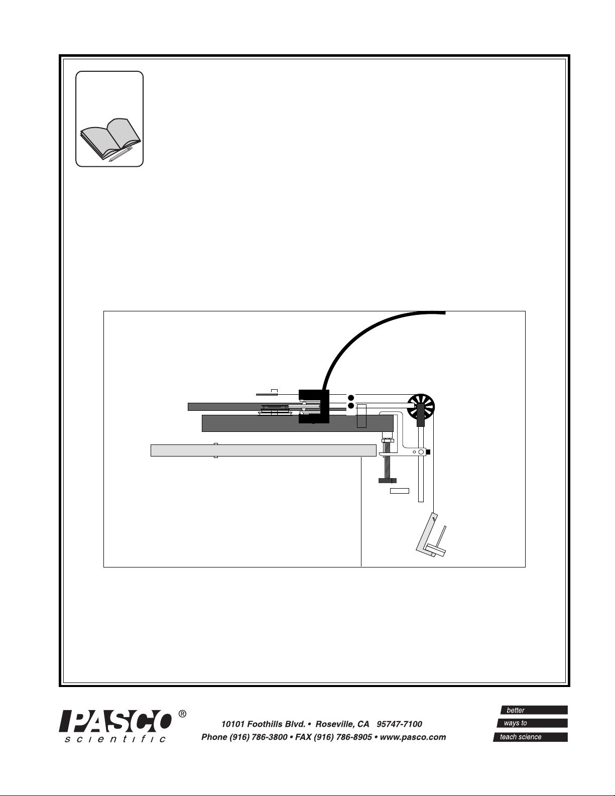
Setup is quick and operation is simple. As shown in
Figure 1, a platter spins on low-friction ball bearing
supports. Torques can be applied to the platter with
various torque arms and forces, and the angular
velocity of the platter can be monitored over time to
determine angular acceleration. The moment of inertia
of the rotating system can be varied by adding a
second platter, a steel ring, or a steel block.
The motion of the platter is described mathematically
by Newton's Second Law in its rotational form: t = Ia,
where t is the applied torque, I is the moment of inertia
of the spinning platter, and a is the angular acceleration of the platter.
F
r
τ = r x F = Ια
Timing with the Smart Pulley
The Smart Pulley (see Figure 1) connects to your
Apple II computer (II+, IIe, IIc, or IIGS), or IBM PC
or compatible, providing automatic data collection,
analysis, and graphing. As the platter spins, the pulley
is held lightly against the rim of the platter, and
therefore spins with the platter. The Smart Pulley
photogate monitors the rotation of the pulley, sending
its signals to the computer for timing and analysis.
The software for the Smart Pulley includes options
designed specifically for use with the Introductory
Rotational Apparatus, producing tables and graphs
showing angular displacement, velocity, and acceleration as a function of time.
The Smart Pulley is more than just a computer timer
for the Rotational Apparatus. When used with an
Apple II or IBM PC computer and standard laboratory
equipment such as an air track or dynamics carts, the
Smart Pulley provides a complete introductory lab in
linear mechanics. See the PASCO catalog for more
information about the Smart Pulley System, or Smart
Pulley Timer and Accessories.
Smart Pulley with photogate
(not included)
Figure 1 Rotational Diagram
Timing the Rotational Motion
A variety of timing systems can be used to measure the
motion of the Introductory Rotational Apparatus. The
most versatile option is the PASCO Smart Pulley.
However, standard photogate timers such as the PASCO
model ME-9206A or ME-9215A can also be used.
➤ NOTE: The original 3-hole Smart Pulley has been
replaced . The new PASCO Smart Pulley has 10
spokes and less friction than the 3-hole pulley. If you
currently have 3-hole pulleys and wish to replace
them with 10-spoke pulleys an upgrade kit is available from PASCO. The upgrade kit includes software
that allows use of either the 3-hole or 10-spoke
pulleys. This manual makes reference to both pulleys.
➤ IMPORTANT: If you are using the Smart
Pulley to time the motion of the Rotational
Apparatus, you should begin by familiarizing
yourself with the setup and operation of the
Smart Pulley. See the Smart Pulley manual and
the Smart Pulley Timer Software Manual.
Timing with a Standard Photogate
Timing for the Rotational Apparatus can also be
performed using a standard photogate timer, such as
PASCO model ME-9206A or ME-9215A. The five
ready-to-use experiments in this manual assume you
are using the Smart Pulley to time your experiments
with the Rotational Apparatus. However, each of
these experiments can be modified for standard
photogate timing. See the section, "Timing with a
Photogate." For more information about photogate
timers, see the current PASCO catalog.
1
Page 6

Introductory Rotational Apparatus 012-03051F
Equipment
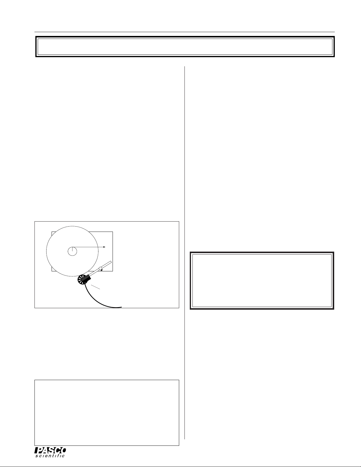
The following equipment is included with the ME-9341
Introductory Rotational Apparatus (see Figure 2):
– Base with leveling supports and main bearing
– Spindle
– Main platter with step pulley
– Pulley clamp
– Tensioning screw
– Level
– Photogate clamp
– Steel bar
– Auxiliary platter
– Steel ring
– Instruction manual and experiments guide
You will also need either:
A PASCO Smart Pulley System (Model ME-9420 or
ME-9421) or one of the Smart Pulley Timers (ME9382, ME-9384, ME-9386, or ME-9388) - (Please see
the PASCO catalog for complete details.) - and an
Apple II or IBM PC (or compatible) computer.
➂ To measure the radius of the Smart Pulley outer cir-
cumference, roll the Smart Pulley over a smooth,
flat surface. Measure the distance, L, over which
you pull the pulley for a predetermined number, n,
of LED flashes. Again, the radius of the outer circumference of the pulley is r = 3L/2 n for a 3-hole
pulley or r = 10L/2 n for a 10-spoke pulley. (You
can draw a mark on the edge of the rim of the Smart
Pulley to use as a reference mark for measuring L.)
➤NOTE: If you would rather not make the
measurements yourself, use the values in the box
below. They should be valid to within 10
percent for your Rotational Apparatus.
Main platter: Mass = 991 gm; Radius = 12.7 cm;
-3
Moment of inertia = 7.50 x 10
kgm
2
Step pulley: Radii = (1.50 cm, 2.00 cm, 2.50 cm)
Auxiliary platter: Mass = 894 gm; Radius = 12.7
-3
cm; Moment of inertia = 7.22 x 10
kgm
2
or
A photogate timing system such as PASCO Model
ME-9206A or ME-9215A.
Measuring Equipment Parameters
In experiments with the Rotational Apparatus, you
will often be comparing experimentally determined
values, such as moment of inertia or angular acceleration, with calculated values based on theory. These
listed, precalculated values may be helpful in those
calculations. For best results, however, we recommend that you make the necessary measurements
yourself. The following suggestions may be helpful
in making certain measurements accurately:
➀ To measure the radii of the step pulley, use calipers
to determine the diameter, then divide by two.
➁ To measure the radius of the Smart Pulley groove,
observe the LED on the top of the photogate as you
pull a string over the pulley. Measure the distance,
L, through which you pull the string for a predetermined number, n, of LED flashes. The radius of
the pulley groove is then r = 3L/2 n for a 3-hole
pulley or r = 10L/2 n for a 10-spoke pulley.
Steel bar: Mass = 690 gm; Dimensions = 22.2 x
5.1 cm; Moment of inertia = 2.98 x 10⁻³ kgm
2
Steel ring: Mass = 701 gm; Outer radius = 6.4 cm;
Inner radius = 5.4 cm;
Moment of inertia =2.46 x 10⁻³ kgm
Smart Pulley: 3-hole 10-spoke
radius inside groove 2.29 cm 2.38 cm
radius outside circum. 2.51 cm 2.54 cm
moment of inertia 15.3x10⁻⁷kgm
2
2
18.6x10⁻⁷kgm
Note: Platters of the earlier versions of the ME9341 were made from masonite. Their mass and
moment of inertia are given below.
Main platter: Mass = 776 gm; Radius = 12.7 cm;
-3
2
Moment of inertia = 6.01 x 10
kgm
Auxiliary platter: Mass = 694 gm; Radius = 12.7
cm; Moment of inertia = 5.82 x 10⁻³ kgm
2
2
2
Page 7

012-03051F Introductory Rotational Apparatus
Bearing
Leveling
supports
Spindle
Step pulley
Base
Pulley clamp
Tensioning
screws (2)
Bubble level
Steel ring
Photogate
clamp
Main platter
Steel bar
Figure 2 Rotational Apparatus Equipment
Auxiliary platter
3
Page 8
Introductory Rotational Apparatus 012-03051F
Setup
➀ Place the base on a flat table. Place the bubble
level on top of the base, then adjust the leveling
supports until the top of the base is level.
➤ NOTE: Leveling the base is important. Not
only does it ensure the accuracy of your experimental results, it also prevents uneven wear on
the bearings.
➁ Slide the spindle into the bushing of the bearing
assembly. Either end of the spindle can face up,
but you will want the long end facing up if you plan
on using the auxiliary platter, the ring, or the bar.
➂ Place the Main Platter over the spindle. The step
pulley can face up or down, but should face down
if you plan on using the auxiliary platter, the ring,
or the bar.
If you are using a standard photogate timer:
➃ See the "Timing with a Photogate" section.
If you are using the Smart Pulley:
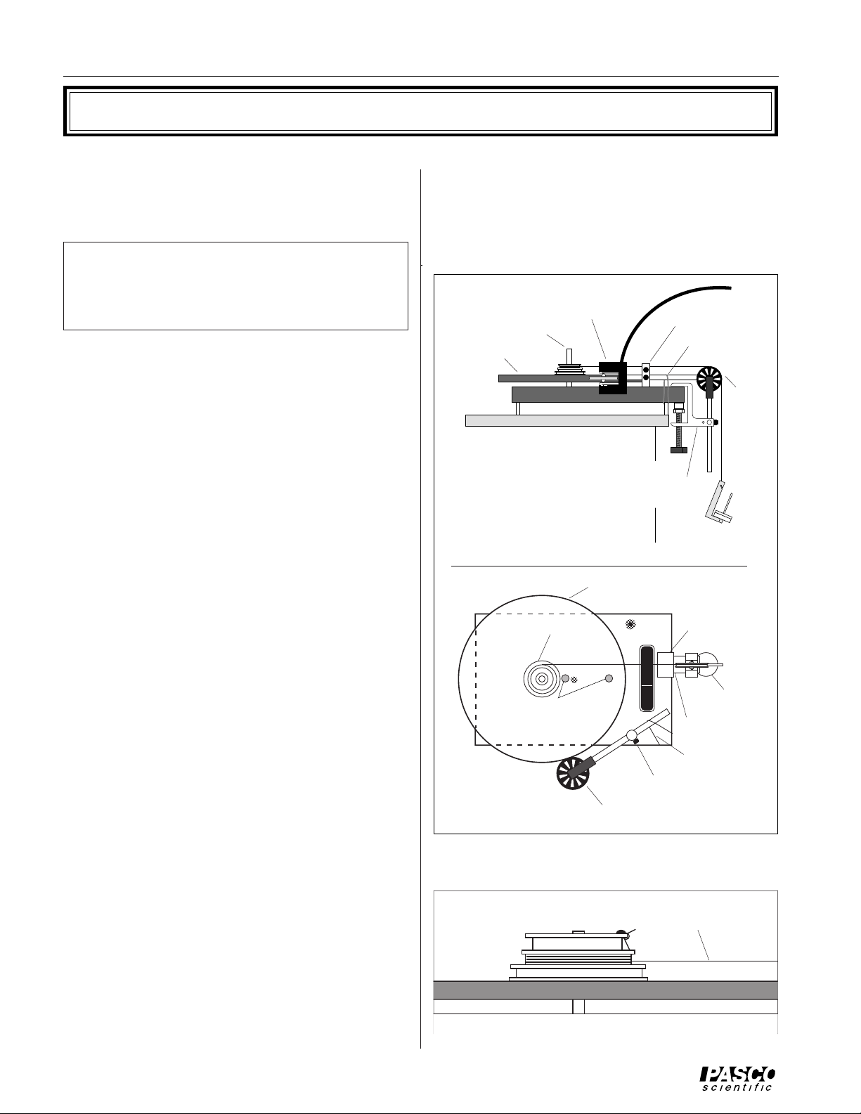
➄ Slide the stem of the Smart Pulley clamp into ei-
ther of the two bushings near the edge of the base.
➅ Place the Smart Pulley rod through the hole in the
Smart Pulley clamp, level the pulley, and tighten
the screw. (Use the upper hole in the clamp if the
Step pulley is facing down, the lower hole if the
step pulley is facing up.)
➆ If you wish, attach a rubber band (not included)
over the rod of the Smart Pulley and a leg under
the base, as shown in Figure 3. This can be useful
in collision experiments, in which an extra "hand"
may be needed to keep the Smart Pulley in contact
with the platter.
➇ See the Smart Pulley System manual for connect-
ing and using the Smart Pulley. For most experiments using the rotational apparatus, you will want
to use Option M – MOTION TIMER from the
Smart Pulley main menu. When you are ready to
begin timing, just press the Smart Pulley lightly
against the edge of the platter.
If you are applying torque with a hanging mass:
➉ Thread the thread through the holes in the step pul-
ley to the desired level. (For instance, thread it
through one hole if you are using the smallest pulley, two holes if you are using the medium size pulley, etc.)
Smart Pulley
Spindle
Main platter
(SIDE VIEW)
Main platter
Spindle
Tensioning Screws
(TOP VIEW)
Figure 3 Setting Up the Rotational Apparatus
Smart Pulley
Smart Pulley clamp
Rubber band
Pulley
Universal
Clamp
Hanging
Mass
Universal
Clamp
Hanging
Mass
Pulley
Rubber band
Smart Pulley clamp
Thread parallel to
platter.
➈ Attach a piece of thread to the step pulley using the
screw to hold the thread, or tying it to the hole in
the smallest pulley (see Figure 4).
Figure 4 Threading the Step Pulley
4
Page 9

012-03051F Introductory Rotational Apparatus
11 Attach a pulley to the base of the apparatus using
the Smart Pulley table clamp as shown in Figure 3.
If you don't have the table clamp, a pulley mounted
to a ring stand can be used, as long as the height
and angle of the pulley are adjustable.
NOTE: When using a falling mass to accelerate
the platter, there are two setup options.
Option a—This option requires the Smart Pulley
and a second pulley, set up as shown in Figure 3.
This method is slightly less accurate than option
b, but conceptually simpler. When entering the
graphing mode of the Smart Pulley software, you
will be asked to identify the type of device being
used to interrupt the photogate. If you are using
the version of Smart Pulley Timer software that
functions with either 10-spoke or 3-hole pulleys,
simply choose ROTATIONAL APPARATUS.
If you are using an older version of Smart Pulley
Timer and a 3-hole pulley, choose ROTATIONAL
APPARATUS. However, if you are using an
older version of Smart Pulley Timer software and
a 10-spoke pulley, choose OTHER (ANGULAR
MEASUREMENT). The computer will ask you
to enter the angle in radians between the spokes.
Enter 0.125 [calculated by using θ = 2π/10
(R
SMART PULLEY/RMAIN PLATTER)]. The computer
will then automatically convert the measured
times to determine the angular displacement,
velocity, and acceleration of the platter. The
slight decrease in accuracy results from the
friction caused by the pressure of the Smart
Pulley on the rim of the spinning platter.
12 Pass the thread over the pulley and adjust the pulley
angle and height so the thread is parallel with the
platter surface and with the groove in the pulley.
Option b—In this option, use the Smart Pulley
as the pulley that supports the hanging weight.
No other pulley is needed. When asked by the
computer to identify the type of device being
used to interrupt the photogate, select option F—
OTHER (ANGULAR MEASUREMENT). You
will then be asked to enter the angle between
openings. Enter one of the values shown below,
depending on which tier of the step pulley you
are using and the type of Smart Pulley you have
(these values are the angle, in radians, through
which the platter turns for each signal sent to the
computer by the Smart Pulley).
Tier of step pulley used 3-hole 10-spoke
Smallest 3.20 1.00
Middle 2.49 0.75
Largest 1.92 0.60
These values can be calculated using the formula:
θ = 2 /3 (Rp/Rsp) for a 3-hole pulley
or θ = 2 /10 (Rp/Rsp) for a 10-spoke pulley
where Rp is the radius of the Smart Pulley
groove, and Rsp is the radius of the tier of the
step pulley that is being used.
5
Page 10

Introductory Rotational Apparatus 012-03051F
Timing with a Photogate
If you don't have the Smart Pulley system, a PASCO
photogate can be used to time the Rotational Apparatus. Other photogates can be used as well. The
Rotational Apparatus includes a mounting clamp that
should work with most photogates.
To Use a Photogate:
➀ Mount the photogate in the photogate clamp, and
mount the photogate clamp in the pulley clamp, as
shown in Figure 5.
➁ Tape a piece of cardboard to the top of the platter
to trigger the photogate. The shape of the cardboard depends on which of the following timing
techniques you choose.
PASCO photogates have three timing modes: Pulse,
Gate, and Pendulum. If your photogate has these
timing modes, any of the following four timing
techniques can be used:
1. PULSE MODE (Method 1)—In pulse mode, the
photogate will be triggered each time the leading
edge of the cardboard interrupts the photogate
beam (see Figure 5). The times displayed will
therefore show the time for one full revolution of
the platter. Experimenters will then have one
revolution to record the time before a new time is
displayed. (Just divide 2 by the measured time to
determine the angular velocity of the platter in radians/second.)
2. PULSE MODE (Method 2)—Tape two pieces of
cardboard to the main platter (see Figure 6). If the
cardboard pieces are accurately placed so the leading edges are along a single diameter of the platter,
the timing resolution is twice as good as with a
single cardboard piece. The displayed times will
show the time per 1/2 revolution of the platter.
Cardboard
Photogate
Figure 5 Pulse Mode (Method 1) and Pendulum
Mode
Figure 6 Pulse Mode (Method 2)
Pulley clamp
Photogate clamp
3. GATE MODE—Tape a one radian sector of card-
board to the top of the main platter (see Figure 7).
In gate mode, for each revolution of the platter, the
timer will display the time during which the cardboard interrupted the photogate. The reciprocal of
the measured times will therefore give the angular
velocity in radians/second. (See the Appendix for
a one radian sector that you can copy and use as a
template for cutting the cardboard.)
One Radian
Sector
Figure 7 Gate Mode
6
Page 11

012-03051F Introductory Rotational Apparatus
4. PENDULUM MODE—If the rotational speed is
too great to record the times as they are displayed,
use a single cardboard piece, as in Figure 5, and set
the photogate to pendulum mode. The timer will
display the time for two full revolutions of the platter, allowing one revolution time for reading and
recording the value.
Five Copy-Ready Experiments
The following five experiments are written in worksheet form.
Feel free to photocopy them for use in your lab.
Some precautions will help keep your data as accurate as
possible:
5. Alternative Methods
• Use the PASCO Model AI-6577A Apple Com-
patible Photogate System. This system offers
many of the same advantages as Smart Pulley
timing. However, since it was not designed specifically for the Rotational Apparatus, experiments will have to be adapted somewhat.
➀ Before conducting any experiment, always level the base as
accurately as possible.
➁ When using a thread to apply a torque to the platter, keep the
thread as parallel to the platter as possible.
➂ When measuring the radius of a tier of the step pulley, use
calipers to measure the diameter, then divide by two.
➤ NOTE: For more information about each of these
labs, including relevant equations and suggested
alternatives, see the LAB NOTES section, near the end
of this manual.
7
Page 12

Introductory Rotational Apparatus 012-03051F
Notes:
8
Page 13

012-03051F Introductory Rotational Apparatus
Experiment 1: Angular Acceleration - 1
EQUIPMENT NEEDED:
- Introductory Rotational Apparatus with auxiliary platter, ring, steel bar, and bubble level
- Smart Pulley with table clamp and software - 2.5-newton spring balance
- Apple II or IBM PC or compatible computer - thread
When a force causes an object to rotate, the angular acceleration of the object depends upon
four factors: (1) the magnitude of the force, (2) the direction of the force, (3) the point on
the object at which the force is applied, and (4) the rotational inertia of the object. In this
lab you will investigate the quantitative relationship between these four factors and the
angular acceleration of a rotating system. A spring balance will be used to apply the force.
Procedure
➀ Set up the apparatus as shown in
Figure 1.1. Place the main platter on
the shaft so that the step pulley is on
top. Use the bubble level to level the
apparatus.
➁ Insert the Smart Pulley Timer soft-
Pull with
constant
force.
ware disk into your computer disk
drive and start up the computer.
[Note: Please refer to the Smart
Figure 1.1 Equipment Setup
Pulley Timer manual.]
➂ Attach a 2-3 meter piece of thread to your spring balance. Attach the other end to the step
pulley and wind it up on the smallest of the three spindles. Hold the Smart Pulley lightly
against the edge of the platter. If the LED on the Smart Pulley photogate is OFF, rotate the
platter slightly until it comes ON.
➃ Now select MOTION TIMER from the main menu. Pull the thread with a constant force of
0.4 newton while the Smart Pulley monitors the motion of the platter. Just
runs out, push <RETURN> to stop the timing.
➄ When the computer finishes calculating the times, examine the data table. If you think your
run was good, press <RETURN>, then select GRAPH DATA to move to the graphing
program. You will be asked to identify the type of device used to interrupt the photogate.
See Option a on page 4. Select ROTATIONAL APPARATUS or OTHER (ANGULAR
MEASUREMENT) depending on which style of Smart Pulley you are using. Then select
VELOCITY VS TIME for a velocity-time graph.
➅ For the graph style, select STATISTICS, so the computer will do a statistical analysis of
your data (press the S-key, then press the space bar so a check appears to the left of your
selection). When the graph is constructed, there will be three sets of numbers at the top.
"M" is the slope of the graph, which is the angular acceleration of the platter in rad/sec
➆ In Table 1.1, record the angular acceleration, the force you applied with the spring balance,
and the radius of the spindle of the step pulley around which the thread was wrapped.
➇ Go back to step 4 and repeat the experiment using the same force, but use the next largest
spindle on the step pulley. Repeat again using the largest spindle.
Smart Pulley
before the thread
2
.
➈ Go back to step 4, use the smallest spindle again, but now use 0.8, 1.2, 1.6 and 2.0 newtons
of force.
9
Page 14

Introductory Rotational Apparatus 012-03051F
➉ Turn the platter over. Go back to step 4. Use the smallest spindle and 0.4 newton of force.
Place the auxiliary platter on top of the main platter, and repeat the experiment. If you have
additional platters, repeat again using two or three platters on top of the main platter. Now
repeat the experiment first with the ring and then the steel bar on top of the main platter.
Analysis
Draw a graph of angular acceleration versus the step pulley
radius, given a constant applied force. Draw a second graph
of angular acceleration versus the applied force for a constant
step pulley radius. The angular acceleration of an object (a)
depends upon the torque (τ) applied to it and the moment of
inertia (I) of the object: a = τ/I. Torque equals the applied
force times the perpendicular distance from the axis of
rotation to the point of application of the force, τ = d⊥ F (see
Figure 1.2).
In step 8 of the procedure, the applied force remained constant while the distance d
changed (d⊥ is the step pulley radius). In your first graph, you should see that the angular
acceleration is directly proportional to d⊥.
In step 9 of the procedure, d
remained constant while the applied force was changed. There-
⊥
fore, your second graph should show that angular acceleration is directly proportional to the
applied force.
Finally, the angular acceleration is inversely proportional to the moment of inertia, given a
constant torque. The moment of inertia of an object depends on its mass and on how that mass
is distributed. In the first part of step 10, you increased the mass but kept the distribution the
same. What affect did the increased mass have on the acceleration? What affect did it have on
the moment of inertia?
The auxiliary platter, the ring, and the bar have approximately the same mass. Based on your
acceleration data, rank them from greatest to least in terms of their moments of inertia. Be
prepared to explain your logic for ranking them as you did in your Discussion. Do your results
agree with theory?
F
d
⊥
τ = d⊥ F
α = τ/Ι
Figure 1.2 The Geometry of Torque
was
⊥
Report
Your report should include PURPOSE, PROCEDURE, DATA, and DISCUSSION. Your
discussion should include your Analysis. Compare rotational dynamics with linear dynamics
in your discussion.
Name: Date: Group:
Table 1.1 Data
Description of Applied Force Step Pulley Radius Angular Acceleration
Rotating Object (F)(d⊥)(α)
10
Page 15

012-03051F Introductory Rotational Apparatus
Experiment 2: Angular Acceleration—2
EQUIPMENT NEEDED:
- Introductory Rotational Apparatus with auxiliary platter, ring, steel bar, and bubble level
- Smart Pulley with table clamp and software - thread
- A second pulley with rod - mass hanger with mass set
- Apple II or IBM PC or compatible computer,
When a force causes an object to rotate, the angular acceleration of the object depends upon
four factors: (1) the magnitude of the force, (2) the direction of the force, (3) the point on the
object at which the force is applied, and (4) the rotational inertia of the object. In this lab you
will investigate the quantitative relationship between these four factors and the angular acceleration of a rotating system. A falling mass will be used to apply the force.
Procedure
➀ Set up the apparatus as shown in Figure 2.1.
Then use the bubble level to level the apparatus.
➁ Insert the Smart Pulley Timer software disk into
your computer disk drive and start up the computer.
[Note: See Smart Pulley manual.]
➂ Attach a 2-meter piece of thread to the step
pulley and wind it up on the smallest of the three
spindles. Attach the mass holder to the other end
of the thread by wrapping 4-5 turns around it.
Add masses to a total of 40 grams (remember,
the mass of the hanger is 5 grams).
➃ Hold the Smart Pulley lightly against the edge of
the platter. If the LED is OFF, rotate the platter
Figure 2.1 Equipment Setup
slightly until it lights up. Now select MOTION TIMER from the main menu. Release the
mass so it falls while the Smart Pulley monitors the motion of the platter. Just
before the mass
hits the floor or the thread runs out, push <RETURN> to stop the timing.
➄ When the computer finishes calculating the times, examine the data table. If you think your
run was good, press <RETURN>, then select GRAPH DATA to move to the graphing program. When asked to identify the type of device you used to interrupt the photogate, select
ROTATIONAL APPARATUS. Then select VELOCITY VS TIME for a velocity-time graph.
➅ For the graph style, select STATISTICS, so the computer will do a statistical analysis of your
data (press the S-key, then press the space bar so a check appears to the left of your selection).
When the graph is constructed, there will be three sets of numbers at the top. "M" is the slope
of the graph, which is the angular acceleration of the platter in rad/sec
2
.
➆ In Table 2.1, record the angular acceleration, the mass you used, and the radius of the step
pulley spindle around which the thread was wrapped.
➇ Repeat steps 4-7 with the same mass but the next largest spindle of the step pulley. Then
repeat again using the largest spindle.
➈ Repeat again, using the smallest spindle, but use masses of 80, 120, 160, and 200 grams.
11
Page 16

Introductory Rotational Apparatus 012-03051F
➉ Turn the platter over and place the auxiliary platter on top. Go back to step 4. Use the
smallest spindle and 40 grams total mass. Repeat the measurements using two and then
three auxiliary platters, if you have them. Now try the experiment first with the ring and
then with the steel bar on top of the main platter.
Analysis
Graph angular acceleration versus step pulley radius, given a
constant value for the falling mass. Also graph angular
acceleration versus the value of the falling mass for a constant step pulley radius. The angular acceleration of an object
(a) depends upon the torque (τ) applied to it and the moment
of inertia (I) of the object: a = τ/I. Torque equals the
applied force times the perpendicular distance from the axis
of rotation to the point of application of the force, τ = Fd⊥.
In this case, the applied force is the tension, T, in the string.
T must be less than mg, the weight of the falling mass, since
m must experience a net downward force in order to accelerate downward. However, for m less than 40 grams, the step pulley radii are small enough
that the approximation T=mg results in a less than 1% error in the angular acceleration (see
Lab Note on Experiment 2, page 17, for details). Thus, as an approximation, use mg as the
applied force.
F
d
⊥
τ = d⊥ F
α = τ/Ι
Figure 2.2 The Geometry of Torque
Report
Beyond
In step 8 of the procedure, the applied force (mg) remained constant while the distance, d
⊥
changed (d⊥ is the step pulley radius). In your first graph, you should see that the angular
acceleration is directly proportional to d⊥.
In step 9 of the procedure, d
remained constant. Therefore, your second graph should
⊥
show that angular acceleration is directly proportional to the applied force.
Finally, the angular acceleration is inversely proportional to the moment of inertia, given a
constant torque. The moment of inertia of an object depends on its mass and on how that
mass is distributed. In the first part of step 10, you increased the mass but kept the distribution the same. What affect did the increased mass have on the acceleration? What affect
did it have on the moment of inertia?
The platter, the ring, and the bar have approximately the same mass. Based on your acceleration data, rank them from greatest to least in terms of their moments of inertia. Be
prepared to explain your reasoning. Do your results agree with theory?
Your report should include Purpose, Procedure, Data, and Discussion. Your Discussion
should include your analysis. Compare rotational dynamics with linear dynamics in your
Discussion.
In the Analysis above, the effect of the acceleration of the falling mass was neglected. If
your instructor wishes, include this effect and analyze this more complex situation in your
discussion and analysis.
12
Page 17

012-03051F Introductory Rotational Apparatus
Name: Date: Group:
Table 2.1 Data
Description of Applied Force Step Pulley Radius Angular Acceleration
Rotating Object (F)(d⊥)(α)
13
Page 18

Introductory Rotational Apparatus 012-03051F
Notes:
14
Page 19

012-03051F Introductory Rotational Apparatus
Experiment 3: Gravitational - Rotational Energy
EQUIPMENT NEEDED:
- Introductory Rotational Apparatus - mass hanger and mass set
- Smart Pulley with table clamp and software, - second pulley with rod
- meter stick - thread
- Apple II or IBM PC or compatible computer
Introduction
In this experiment, you will use a falling mass to apply a constant torque to a rotating
platter. As the mass falls, it loses gravitational potential energy. This lost energy is gained
by the platter as rotational kinetic energy. By measuring the energy lost by the mass and
the energy gained by the platter, you will be able to determine if energy is conserved.
Procedure
➀ Set up the apparatus as shown in
Figure 3.1, with the step pulley
facing up. Use the bubble level to
level the apparatus.
➁ Insert the Smart Pulley software
disk into your computer disk drive
and start up the computer.
[Note: See Smart Pulley manual.]
➂ Measure r, the radius of the
smallest spindle, and record the
value in Table 3.1. Attach a 1.5-meter piece of thread to the step
pulley and wind it up on the smallest of the three spindles. Attach
the mass hanger to the thread, high enough on the thread so the
masses will not hit the floor at the lowest part of their fall. Add
masses to the holder, so the total mass is approximately 50 grams.
Record the total mass as m in the data table. Also measure and
record h
, the distance of the hanging mass from the floor.
1
➃ Hold the Smart Pulley lightly against the edge of the platter. Select
MOTION TIMER from the main menu. Allow the mass to fall
while the Smart Pulley monitors the motion of the platter. Allow the
Figure 3.1 Equipment Setup
mass to reach its maximum drop and begin its rise, then push <RETURN> to stop the timing.
➄ When the computer finishes calculating the times, select GRAPH DATA to move to the
graphing program, selecting ROTATIONAL APPARATUS so the computer knows you are
using the Rotational Apparatus, and then VELOCITY VS TIME for a velocity-time graph.
h
1
h
2
➅ Examining the graph, you should note that there is a point of maximum velocity, corre-
sponding to the point where the gravitational potential energy reached a minimum and the
rotational kinetic energy reached a maximum. Press <RETURN>, then choose DISPLAY
TABLE OF DATA to see a table of the data. Determine the maximum angular velocity of
the platter, given in rad/sec. Record this value as ω
max
15
in Table 3.1.
Page 20

Introductory Rotational Apparatus 012-03051F
➆ Now let the mass hang with the thread fully extended. Measure the distance between the mass
and the floor, and record this value as h2.
➇ Repeat your measurements at least three times, keeping h
constant. Repeat more times if your
1
data shows any inconsistencies between trials.
➈ Repeat steps 4-9, but change the mass to 100, 150, and then 200 grams.
➉ Further experimentation can be done with different spindles of the step pulleys and with
different numbers of platters. Follow your instructor's direction.
Analysis
For each trial, calculate GPE ( mg h ), the gravitational potential energy lost by the falling
mass. Also calculate RKE ( 1/2 I ω
disk. (For your disk, the value for I is 7.75 x 10⁻³ kgm2.) Was energy conserved?
Part of the gravitational energy also went into the kinetic energy, KE (1/2 mv
mass. To determine this quantity, calculate v
pulley over which the thread passes. Calculate the translational kinetic energy and add it to the
rotational kinetic energy. Is energy conserved now?
2
), the rotational kinetic energy gained by the rotating
max
max
= rω
, where r is the radius of the step
max
Report
Your report should include Purpose, Procedure, Data, and Discussion.
2)
, of the falling
Name: Date: Group:
Table 3.1
Data
Trial r m h
1
h
ω
2
max
GPE RKE KE RKE + KE
Calculations
16
Page 21

012-03051F Introductory Rotational Apparatus
Experiment 4: Frictional Torque
EQUIPMENT NEEDED:
- Introductory Rotational Apparatus
- Smart Pulley with rod and table clamp (another pulley will work, the photogate is not
needed)
- Mass hanger with mass set
- Thread
- Meter stick.
Introduction
In order to apply Newton's equations of motion, all the forces acting on the system under
investigation must be known. In any mechanical system, however, there are usually unmeasured frictional forces, so it often appears as if the motion of the system is not in complete
accord with Newton's laws.
In this lab, you will use a falling mass to provide a torque that will rotate a platter. The
energy lost by the falling mass will supply the rotational kinetic energy of the spinning
platter. Then, as the mass is pulled back up by the platter, the platter will again slow down,
its kinetic energy transformed back into the gravitational potential energy of the rising
mass. However, the mass will not rise all the way to its original height, because some
energy has been lost due to friction. By assuming that energy is conserved in this system,
you will determine the amount of frictional torque acting in the Introductory Rotational
Apparatus.
Procedure
➀ Set up the apparatus as
shown in Figure 4.1,
with the step pulley on
top. Then use the
bubble level to level
the apparatus.
Note: In this
experiment the Smart Pulley should be mounted on the lab
table far enough from the apparatus to keep the tread angle
from the spindle to the pulley as small as possible. If the angle
is too great the thread will snap as the mass is pulled back by
the platter and the thread rewinds on the spindle.
➁ Attach a 1.5 meter piece of thread to the step pulley and wind it
up on the smallest of the three spindles. Measure and record r,
the radius of the spindle, in Table 3.1. Attach the mass hanger
so that when the thread is fully extended the hanger will not
reach the floor. Extend the thread and measure h
from the floor to the mass hanger.
, the distance
o
h
2
h
o
Figure 4.1 Equipment Setup
h
1
➂ Place 100 grams on the hanger, and record the total mass, m, in the data table.
17
Page 22

Introductory Rotational Apparatus 012-03051F
➃ Now raise the mass to a starting height of approximately 1 meter. Measure this height care-
fully and record it as h1. Release the mass so it falls, reaches it lowest point, then rises again.
Measure and record, h2, the greatest height that the mass hanger rises to in its ascent.
➄ Repeat your measurement three times, starting from the same h
, and recording the value of h2.
1
➅ Repeat steps 3-5, changing the mass on the hanger, first to 150 grams, then to 200 grams. If
instructed, try the same mass with another pulley. If instructed, repeat the measurements with
two platters. In each case, record the same five values in Table 4.1.
Analysis
Average the final heights, h2, for each set of three trials that were performed under identical
conditions. For each trial, determine the amount of gravitational potential energy lost ( GPE)
by the mass in falling from h1 to h2avg: GPE = mg(h2 – h1).
Determine the total distance that the mass moved, d = [(h
– h 0) + (h2 – ho)] = h1 + h2 – 2ho.
1
From this value, and the radius of the step pulley spindle, determine the angular distance, in
radians, that the platter moved: θ = d/r.
Now calculate the magnitude of the frictional torque, τ
, using the relationship τf θ = GPE.
f
Compare your results for τf under the different experimental conditions that you tried.
Report
Your report should include Purpose, Procedure, Data, and Discussion. Include your Analysis
in the Discussion.
Name: Date: Group:
Table 4.1 Data
Trial r m h
Table 4.2 Calculations
h
o
h
1
h
2
h
2
2
Trial h2 (avg) GPE d θτ
f
18
Page 23

012-03051F Introductory Rotational Apparatus
Experiment 5: Rotational Collisions
EQUIPMENT NEEDED:
- Introductory Rotational Apparatus
- Smart Pulley with table clamp and software
- Auxiliary platter
- An Apple II or IBM PC or compatible computer
Introduction
A rotating platter has rotational kinetic energy, RKE, and angular momentum, L. In a
collision between two platters, the sum of the angular momentums (L1 + L2) following the
collision will be equal to the sum of the angular momentums before the collision. In this
lab, you will investigate this relationship in a particular case—that in which one of the
platters has no initial angular momentum.
Procedure
➀ Set up the apparatus as shown in Figure 5.1.
Mount the main platter so the step pulley is facing
Auxiliary platter
downward. Level the apparatus.
➁ Insert the Smart Pulley software disk into your
Main platter
computer disk drive and start up the computer.
[Note: See Smart Pulley manual.]
➂ Hold the Smart Pulley just off the edge of the
platter. Select MOTION TIMER from the main
menu.
Figure 5.1 Equipment Setup
➃ Hold the auxiliary platter just above the main
platter of your Introductory Rotational Apparatus. Give the main platter a spin using your
hand. Push the Smart Pulley lightly against the spinning platter, and after about 25 data
points have been taken, drop the auxiliary platter onto the spinning one.
➄ Hold the Smart Pulley against the platter until it has taken about 50 data points, then push
<RETURN> to stop the timing.
➅ When the computer finishes calculating the times, select GRAPH DATA to move to the
graphing program, selecting ROTATIONAL APPARATUS so the computer knows you are
using the Rotational Apparatus, and then VELOCITY VS TIME for a velocity-time graph.
➆ Examining the graph, you should note that there are two sections that are straight lines,
showing the platter slowing down. They are joined by a region where the platter abruptly
slowed down due to the second platter colliding with it. Press <RETURN> then choose
DISPLAY TABLE OF DATA to see a table of the angular velocities. Determine the
angular velocity immediately before the collision (ω
) and immediately after (ωf). Record
0
these values in Table 5.1.
➇ Repeat this process a total of three times, recording your data each time.
➈ If you have additional platters try dropping two platters on one, or one on two. Also, if
directed, use the ring as the second, or dropping, object. Then use the steel bar. When
dropping the ring, be careful to center it over the platter and drop it with the pins up.
19
Page 24

Introductory Rotational Apparatus 012-03051F
Analysis
Angular momentum L is equal to the moment of inertia I
times the angular velocity ω. Calculate L
momentum before each collision, and L
momentum after the collision. For I, use 1/2 MR
the platters (the step pulley can be safely neglected),
2
for the ring, and 1/12 M(A2 + B2) for the bar (see
MR
Figure 5.2). Check the conservation of angular momentum by calculating the percentage difference between L
and Lf in each case.
If instructed, calculate the initial and final rotational kinetic energy, showing your results in
Table 5.2. Was RKE conserved in the collisions?
Report
Your report should include Purpose, Procedure, Data, and Discussion.
Name: Date: Group:
Moving Dropping %
Trial Object Object ω
, the angular
o
, the angular
f
2
Table 5.1
o
for
B
A
I = 1/12 M(A
2
+ B2)
Figure 5.2 Calculating the Moment of
o
ω
f
Inertia for the Bar
L
o
L
f
Difference
10
1
2
3
4
5
6
7
8
9
20
Page 25

012-03051F Introductory Rotational Apparatus
Table 5.2
Trial
10
RKE
0
RKE
f
% Difference
1
2
3
4
5
6
7
8
9
21
Page 26

Introductory Rotational Apparatus 012-03051F
Notes:
22
Page 27

012-03051F Introductory Rotational Apparatus
Teacher's Guide
Exp 1 – Angular Acceleration - 1
Introduction
Applying torque with a spring balance ensures that the applied force is simple to understand, as opposed to using a
falling mass, as in Experiment 2. The disadvantage is the inherent inaccuracy of using a hand-pulled device.
Students measure the force and the torque arm, each of which can be independently varied, so the effects of each
on acceleration can be examined. Moment of inertia can also be qualitatively investigated, yielding relative
values.
Alternatives
➀ Larger forces than those listed in the lab sheet can be used. However, the speeds increase and the difficulty in
maintaining a constant torque also increases.
➁ For a shorter lab period, all students could do steps 1-7. The class can then be split into three groups to carry
out steps 8, 9, and 10.
Notes – on Procedure
➂ For best results on all of these labs, use a fine thread and make sure that the thread is wound evenly around the
spindle without overlapping.
➃ It is difficult to maintain a constant
force on the string. We found that
the best results were obtained when
the data was taken for a short time
(about 1 second) rather than for the
entire length of the string.
➇ The larger spindles are proportion-
ally more difficult to maintain at a
constant force, due to the higher acceleration.
➈ The higher forces are also harder to
maintain, for the same reason.
Object Force (N) R (m) alpha (rad/s/s)
base plate: 0.4000 0.0150 0.9724
1.0000 0.0150 2.3181
2.0000 0.0150 4.5086
0.4000 0.0200 1.5984
1.0000 0.0200 2.7110
0.4000 0.0250 1.5645
1.0000 0.0250 3.7425
B.P. + ring 0.4000 0.0150 0.8913
1.0000 0.0150 1.7716
1.8000 0.0150 2.9834
2.0000 0.0150 3.2425
average
B.P. + disk 0.4000 0.0150 0.5763
1.0000 0.0150 1.2496
2.0000 0.0150 2.0803
B.P. + bar 0.4000 0.0150 0.7808
1.0000 0.0150 1.5346
2.0000 0.0150 3.7007
23
Page 28

Introductory Rotational Apparatus 012-03051F
Notes – on Analysis
Acceleration vs. Radius
Acceleration vs. Radius
Force = 1.0 N
The acceleration is directly proportional to the radius for a constant
force.
4
3.5
3
2.5
2
1.5
1
Angular Acceleration
0.5
0
0 0.005 0.01 0.015 0.02 0.025 0.03
Force = 1.0 N
●
●
●
Radius
Acceleration vs. Force
Acceleration vs. Force
Radius = 1.5 cm
Radius = 1.5 cm
The acceleration is directly proportional to the
force for a constant radius.
Increasing the mass by adding another disk
increased the rotational inertia and decreased
the acceleration.
5
4.5
4
3.5
3
2.5
2
1.5
Angular Acceleration
1
0.5
0
0 0.2 0.4 0.6 0.8 1 1.2 1.4 1.6 1.8 2
Base plate alone
●
❍
❍
With added disk
Applied Force
●
●
❍
Ranking the three objects in increasing order of inertia would give: ring, bar, then disk. This is misleading,
because for objects of the same mass and radius the ring would have the highest inertia. The lower inertia of the
ring is due to its smaller radius, not its shape.
Using the spring scale as a constant-force apparatus is good in a way because it allows the student to directly see
that the acceleration is proportional to the force, without messing around with the falling masses as in experiment
2. Its accuracy is limited, however, by the difficulty in maintaining a constant force on the scale. For this reason, I
would consider experiment 2 to be preferable to experiment 1 for anything but the most basic introductory course.
24
Page 29

012-03051F Introductory Rotational Apparatus
Exp 2 – Angular Acceleration - 2
Introduction
In its simplest form, the principles in this lab are very clear, the setup is easy, and the variables are easy to control.
However, in its simplest form, the lab assumes that the mass exerts a constant force of F = mg on the platter.
Since the mass is accelerated along with the platter, the tension (T) on the thread must be less than the mass. An
accurate analysis of the motion must take into account that T, not F, is the force that accelerates the platter. The
following equations and diagram derive the rotational acceleration, a, using T as the force that causes the platter to
rotate.
mg - T = ma = mrα
τ = Tr = Iα
a = rα
→ T = mg - mrα
τ = mgr - mr2α = Iα
mgr = Iα + mr2α
α = (mgr)/(I + mr2)
For large masses or for large values of r, the mr2 term in the denominator may have a significant impact. For a
mass of 200 grams and a radius of 1.5 cm, the mr2 term reduces the rotational acceleration only by 0.8%. Therefore, the decision to neglect this factor does not detract significantly from the final results. However, students can
be given the option of trying to prove the theoretical results as given above.
Alternatives
➀ See Experiment 1: Angular Acceleration - 1.
➁ For a more accurate, but somewhat less straightfor-
ward method, see "Option b" in the note on page 4.
Radius of step pulley
spindle = r
I = Moment of inertia of the platter
= MR2 for a cylinder.
τ = Torque = r x T
Experiment 2: Diagram of Relevant Variables
T
(Tension)
m
F = mg
Notes – on Procedure
➂ Using a lighter mass than 40 grams will give good results, as long as it is heavy enough that the frictional
torque may be ignored.
➃ Use a lightweight rubber band to hold the smart pulley against the platter. The pulley should be held with just
enough tension to keep it from slipping; any extra tension will add to the friction of the system.
➈ Using the heavier masses will introduce significant errors due to the linear acceleration of the mass. These er-
rors are negligible when lighter masses are used.
25
Page 30

Introductory Rotational Apparatus 012-03051F
average
Object Mass (g) Force (N) R (m) alpha (rad/s/s)
Base Plate 25.5700 0.2506 0.015 0.4111
46.3500 0.4542 0.015 0.8646
87.2300 0.8549 0.015 1.6976
117.4100 1.1506 0.015 2.3157
157.7600 1.5460 0.015 3.1756
191.7200 1.8789 0.015 3.8850
B.P. + ring 25.5700 0.2506 0.015 0.2858
B.P. + disk 25.5700 0.2506 0.015 0.1917
B.P. + bar 25.5700 0.2506 0.015 0.2694
B.P. 25.5700 0.2506 0.015 0.4472
25.5700 0.2506 0.020 0.6253
25.5700 0.2506 0.025 0.7704
Notes – on Analysis
The acceleration is directly proportional to the radius for a
constant force.
The acceleration is directly proportional to the force for a
constant radius.
Increasing the mass by adding another disk increased the
rotational inertia and decreased the acceleration.
Ranking the three objects in increasing order of inertia would
give: ring, bar, then disk. This is misleading, because for
objects of the same mass and
radius the ring would have the
highest inertia. The lower inertia of the ring is due to its
smaller radius, not its shape.
Notes
The assumption that the force on the turntable equals mg is valid
only for small masses and acceleratons. Using larger masses will
lessen your accuracy in this experiment. If the masses used are too
small, then the friction in the device may be proportionally large
enough that it causes errors as well. Generally, keep the falling mass
between about 20 and 200 grams.
With the assumption mentioned, this lab is essentially identical to
experiment 1.
Angular Acceleration v. Radius
Angular Acceleration v. Radius
1
0.8
0.6
0.4
0.2
angular acceleration
0
0 0.005 0.01 0.015 0.02 0.025 0.03
4
3.5
3
2.5
2
1.5
angular acceleration
1
0.5
0
0 20 40 60 80 100 120 140 160 180 200
mass = 25.57g
mass = 25.57g
●
radius (cm)
Acceleration vs. Mass
Acceleration vs. Mass
radius = 1.5 cm
radius = 1.5 cm
●
●
●
mass (g)
●
●
●
●
●
26
Page 31

012-03051F Introductory Rotational Apparatus
Exp 3 – Gravitational-Rotational Energy
Introduction
In this lab, results should verify conservation of energy to within 2% or better. Loss of energy will occur in the
bearings of the Rotational Apparatus, and in the pulley. This loss should remain relatively constant for various
masses pulling the thread. Therefore, for heavier falling masses, since the total energy exchange is greater, the
percentage error will be less. (This can be a useful point for student discussion.)
Alternatives
This experiment might be included in a laboratory in which different student groups carry out different experiments, all related to energy conservation.
Notes – on Procedure
➂ Make sure that the thread is wound evenly—without overlapping itself—for best results.
➆ h
will change as the thread unwinds and stretches. Measure it in each trial for maximum accuracy.
2
smallest step used: r = 0.015
g = 9.8
h1 = 0.651
Average Average Average
Mass (g) Force (N) h
46.35 0.4542 0.0880 8.1307 0.1220 0.8883
96.74 0.9481 0.0840 11.9843 0.1798 1.8756
147.01 1.4407 0.0810 14.7693 0.2215 2.8722
197.22 1.9328 0.0790 17.3205 0.2598 3.9055
2
ω max max wt. vel. alpha
Notes – on Analysis
I = 7.75E-3
mgh 1/2 I ω
0.2557 0.2562 0.0003 0.2565 0.17% 0.31%
0.5375 0.5565 0.0016 0.5581 3.53% 3.82%
0.8212 0.8453 0.0036 0.8489 2.93% 3.37%
1.1055 1.1625 0.0067 1.1692 5.15% 5.75%
2
1/2 m v
Note that in each case the final energy of the system (RKE+ KE) is greater than the original energy (mgh). This is
rather unsettling... (not to mention wrong!) As near as I can tell, the actual moment of inertia of the platter is less
than the value listed in the manual. You can experimentally check the moment of inertia of your own platter (they
vary some due to manufacturing differences) by assuming conservation of energy and then solving for I:
mgh = 1/2 I ω
2
2
+ 1/2 m v
RKE + KE % error (1) % error (2)
2
where w is the angular velocity and v is the linear velocity of the mass m.Using this method, I found the moment
of inertia to be 7.50x10⁻³ ± 3%. This value for I gives me much better results, although the energy is still too high.
27
Page 32

Introductory Rotational Apparatus 012-03051F
I = 7.50E—3
mgh 1/2 I ω
2
1/2 m v
2
RKE + KE % error (1) % error (2)
0.2557 0.2480 0.0003 0.2484 -3.02% -2.89%
0.5375 0.5388 0.0016 0.5404 0.23% 0.52%
0.8212 0.8183 0.0036 0.8219 -0.35% 0.09%
1.1055 1.1255 0.0067 1.1321 1.80% 2.40%
28
Page 33

012-03051F Introductory Rotational Apparatus
Exp 4 – Frictional Torque - Notes and Data
Introduction
This lab is easy and requires no sophisticated electronic equipment. The greatest source of error in this experiment is in measuring the highest point reached by the hanging mass when the spinning platter pulls it back up.
Resist attempts to talk about the friction of the system, unless you also attempt to identify the effective radius at
which the frictional force is applied.
Alternatives
The students give the platter a spin and measure an initial angular velocity. They then count the number of
revolutions until the platter comes to a stop. From the total angle through which the platter rotated, θ, they could
determine the torque using τθ = RKE , where RKE = 1/2 Iω2 = the rotational kinetic energy of the platter.
Notes – on Procedure
➀ Setting up the apparatus with the spindles down will allow you to test the frictional torque with different
masses if desired. Make sure that the pulley is at an appropriate height so that the string will wind onto the desired step automatically.
➃ The frictional torque has been shown to be somewhat dependent on the angular velocity of the base plate.
Since the difference in height that the weight drops affects this velocity, the original height of the weight will
affect the frictional torque measured.
➅ Again, because the friction is dependent on velocity, the mass used will affect the measured friction. The mass
will also affect the friction of the pulley used for support. The greater the mass used, the greater the magnitude
of the measured frictional torque.
Notes – on Analysis
Data
DataData
Data
DataData
Mass (kg) r (m) h0 (m) h1 (m) h2 (m) h2 (m) h2 (m)
B.P. + pulley 0.02523 0.015 0.12 0.651 0.505 0.495 0.430
0.07548 0.015 0.115 0.651 0.572 0.562 0.572
0.12586 0.015 0.112 0.651 0.594 0.595 0.595
0.17610 0.015 0.106 0.651 0.602 0.602 0.604
0.19674 0.015 0.103 0.651 0.605 0.600 0.603
B.P. only 0.09662 0.015 0.115 0.651 0.575 0.575 0.575
0.14683 0.015 0.113 0.651 0.582 0.580 0.581
0.19722 0.015 0.082 0.651 0.598 0.600 0.600
B.P. + disk 0.19722 0.015 0.102 0.651 0.595 0.595 0.595
29
Page 34

Introductory Rotational Apparatus 012-03051F
Calculations frictional average
h2 (avg) GPE (J) d (m) theta (rad) torque (Nm) torque
B.P. + pulley 0.477 -0.043 0.888 59.18 -0.00073
0.569 -0.061 0.990 65.98 -0.00092 compare
0.595 -0.069 1.022 68.11 -0.00102 -0.00104 with
0.603 -0.083 1.042 69.44 -0.00120 below
0.603 -0.093 1.048 69.84 -0.00133
B.P. only 0.575 -0.072 0.996 66.40 -0.00108
0.581 -0.101 1.006 67.07 -0.00150 -0.00132
0.599 -0.100 1.086 72.42 -0.00138
B.P. + disk 0.595 -0.108 1.042 69.47 -0.00156 -0.00156
A second method of measuring the friction was used for comparison. The falling mass and attatched string were
removed and the super pulley was used with the Motion Timer program. The base plate was initially spun by
hand, and the frictional deceleration was measured as the slope of the velocity vs. time graph. (see graph) The
frictional torque was calculated from this deceleration and the known rotational inertia of the base plate.
I = 0.01
ω
o
alpha torque average
B.P. + pulley 6.3575 -0.11244 -0.00084
6.4890 -0.11504 -0.00086
2.8102 -0.10378 -0.00078
2.2213 -0.12181 -0.00091
2.2008 -0.08772 -0.00066 -0.00080
1.2787 -0.10370 -0.00078
0.6177 -0.09142 -0.00069
2.2157 -0.10252 -0.00077
1.7819 -0.12055 -0.00090
3.7205 -0.11370 -0.00085
There is a 23% difference in the measured friction with these two methods; mostly due to the fact that the second
method does not include the friction of the pulley used to hold up the dropping mass.
Notes
Expect a fairly wide spread of results on this
0.25
M = -0.007076
± 0.00001571
VELOCITY VS. TIME
B = 0.2472
± 0.0001405
R = -0.9997
lab. The friction of the system depends on
many factors which may not be completely
controlled, and a 10% variation between
successive identical measurements is not
uncommon.
VELOCITY
0.2
(M/S)
0.15
30
0
0
510
15 20
TIME (SEC)
Page 35

012-03051F Introductory Rotational Apparatus
Exp 5 – Rotational Collisions
Introduction
This lab lets students verify the conservation of
angular momentum. In practice, the graphs that
emerge help students to see that the changes in
rotational speed are not instantaneous. Applications
of this principle abound, such as the decrease in an
engine's speed as the clutch is engaged, or the temporary slowing down of a phonograph turntable as a new
record drops onto it.
Alternatives
➀ This type of experiment can be used to investigate
the moment of inertia of an object. The calculations are left to the instructor, but in practice,
rather than dropping disks onto disks, the ring or
the steel bar can be dropped.
➁ A second type of collision can be created using two
rotational apparatuses. Each platter is given an initial rotational velocity, then the two platters are
butted up against each other as shown below, so
they have a common final rotational velocity. A
rim on one of the disks that permits minimal slipping would help to increase the accuracy of the lab.
➂ With a few do-it-yourself accessories, the Introduc-
tory Rotational Apparatus can be used to demonstrate the conservation of angular momentum as in
the spinning ice skater example. You will need:
1. A piece of U-channel with an inside width of
about 1.2 cm and a length of about 25 cm.
2. A cross-hole spindle as shown in the illustration below.
3. Equal masses of 100-500 grams that will slide
in the channel (the PASCO masses that come
with the Smart Pulley will work).
4. Double-stick tape, thread.
Drill a 1 cm (3/8"+) hole in the center of the U-channel
and attach the spindle as shown in the illustration
below. Attach the U-channel to the platter with
double-stick tape.
Place masses of 100-500 grams on each side of the
channel, and run a piece of thread down the center hole
and out the sides of the cross-hole spindle. Attach
each end of the thread to a mass. Give the platter a
spin. Pull on the thread to vary the distances of the
masses from the center, obtaining a corresponding
increase or decrease in angular velocity.
ω
1
Experiment 5: Alternative Method for Collisions
ω
2
ThreadSpindle
Weight
U-channel
Main platter
Close-up of spindle
Experiment 5: Conservation of Momentum
Demonstration
Weight
Thread
ω
31
Page 36

Introductory Rotational Apparatus 012-03051F
Notes – on Procedure
➂-➄ Rather than go through the process of releasing and engaging the smart pulley each time, I found it easier to
hold the pulley against the platter with a rubber band all the time. Either way works fine, though.
➈ I did not get consistent results when dropping the ring on the disk, due to the difficulty in centering the ring
each time.
Notes – on Analysis
object ω
o
ω
f
I
o
I
f
L
o
L
f
% dif. RKE
RKE
o
f
disk on B.P. 4.30 2.16 0.00750 0.01453 0.032 0.031 2.68% 0.069 0.033
4.00 1.92 0.00750 0.01453 0.030 0.027 7.00% 0.060 0.026
6.75 3.45 0.00750 0.01453 0.050 0.050 0.98% 0.170 0.086
4.06 2.01 0.00750 0.01453 0.030 0.029 4.08% 0.061 0.029
7.20 3.39 0.00750 0.01453 0.054 0.049 8.78% 0.194 0.083
5.14 2.73 0.00750 0.01453 0.038 0.039 -2.89% 0.099 0.054
Bar on B.P. 3.62 2.45 0.00750 0.01052 0.027 0.025 5.06% 0.049 0.031
2.88 2.02 0.00750 0.01052 0.021 0.021 1.61% 0.031 0.021
2.35 1.54 0.00750 0.01052 0.017 0.016 8.08% 0.020 0.012
1.88 1.34 0.00750 0.01052 0.014 0.014 0.02% 0.013 0.009
Bar on B.P.+disk 2.80 2.33 0.01453 0.01755 0.040 0.040 -0.51% 0.056 0.047
3.14 2.60 0.01453 0.01755 0.045 0.045 -0.01% 0.071 0.059
5.48 4.41 0.01453 0.01755 0.079 0.077 2.79% 0.218 0.170
2.24 1.87 0.01453 0.01755 0.032 0.032 -0.83% 0.036 0.030
Angular momentum is conserved, kinetic energy is not.
There is a bit of delay time between when the objects first touch and when they equalize their velocities, and it has
been suggested that friction in the bearings during this delay is a source of error. To investigate this, a rubber band
was placed on top of the base plate and the first part of the experiment was repeated.
This method was found to greatly decrease the delay time, and there is some improvement on the actual results.
(The angular momentum of the rubber band was neglected.)
object ω
o
Disk on B.P. 2.86 1.50 0.00750 0.01453 0.021 0.021 -1.60% 0.031 0.016
(rubber band) 4.01 1.93 0.00750 0.01453 0.030 0.028 6.76% 0.060 0.027
3.01 1.56 0.00750 0.01453 0.022 0.022 -0.41% 0.034 0.018
5.47 2.83 0.00750 0.01453 0.041 0.041 -0.23% 0.112 0.058
ω
f
I
o
I
f
L
o
L
f
% dif. RKE
RKE
o
Another method of analysis, which almost entirely eliminates frictional problems, is to extrapolate both linear
regions of the velocity graph completely across the graph, then measure the instantaneous distance between these
two lines as the difference in velocity before and after the collision.
32
f
Page 37

012-03051F Introductory Rotational Apparatus
Appendix
1-Radian Sector
➤ NOTE: This one radian sector can be photocopied to
provide a template for constructing photogate triggers out of
cardboard. See the "Timing with a Photogate" section in this
manual.
33
Page 38

Introductory Rotational Apparatus 012-03051F
Notes
34
Page 39

Technical Support
Feedback
If you have any comments about the product or
manual, please let us know. If you have any suggestions on alternate experiments or find a problem in the
manual, please tell us. PASCO appreciates any
customer feedback. Your input helps us evaluate and
improve our product.
To Reach PASCO
For technical support, call us at 1-800-772-8700
(toll-free within the U.S.) or (916) 786-3800.
fax: (916) 786-3292
e-mail: techsupp@PASCO.com
web: www.pasco.com
Contacting Technical Support
Before you call the PASCO Technical Support staff,
it would be helpful to prepare the following information:
➤ If your problem is with the PASCO apparatus,
note:
- Title and model number (usually listed on the
label);
- Approximate age of apparatus;
- A detailed description of the problem/sequence
of events. (In case you can’t call PASCO right
away, you won’t lose valuable data.);
- If possible, have the apparatus within reach
when calling to facilitate description of individual parts.
➤ If your problem relates to the instruction manual,
note:
- Part number and revision (listed by month and
year on the front cover);
- Have the manual at hand to discuss your ques-
tions.
Page 40

 Loading...