

Page 1

Instruction Sheet
for the PASCO
Model ME-9204B
ACCESSORY PHOTOGATE
012-06375A
4/97
$1.00
The cable assembly included with the Accessory
Photogate is detachable from the unit. One end of the
cable is a RJ12 telephone plug that connects to the RJ12
modular jack in the photogate housing. At the other end,
a stereo phone plug connects directly into a PASCO
Photogate Timer (ME-9206B and ME-9215B) or into any
PASCO interface with digital channels (ScienceWorkshop
500 I and 700 I). Please note that the ME-9215B has a
memory function which allows signals from two
photogates (the built-in photogate on the ME-9215B and
the ME-9204B) to be stored and retrieved.
The Photogate Head also includes a small rod clamp and
thumbscrew for attaching the unit to the base and support
rod included with the product, or to any quarter inch diameter support rod.
®
ACCESSORY
PHOTOGATE
ME-9204B
Introduction
The PASCO Model ME-9204B Accessory Photogate features a Photogate Head with a narrow infrared beam and
a fast fall time that provide very accurate signals for timing. When the infrared beam between the source and detector is blocked, the output of the photogate is low, and
the red LED (light emitting diode) on the photogate goes
on. When the beam is not blocked, the output is high,
and the LED is off.
Additional Features
The raised slot on the housing provides a seat for attaching the PASCO ME-9450 Super Pulley.
removable
RJ12 connector
Photogate
Head
Super
Pulley
© 1997 PASCO scientific
This instruction sheet edited by: Martina Graham
®
10101 Foothills Blvd. • P.O. Box 619011 • Roseville, CA 95678-9011 USA
Phone (916) 786-3800 • FAX (916) 786-8905 • email: techsupp@PASCO.com
better
ways to
teach science
Page 2
Accessory Photogate 012-06375A
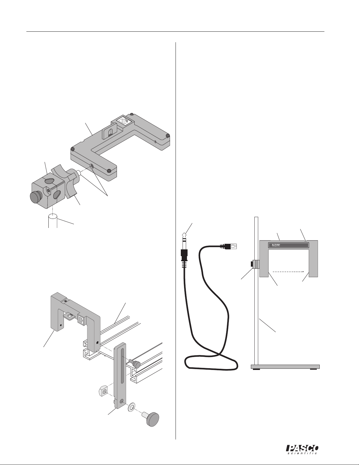
The Photogate Head can be mounted on a support rod of
up to half inch in diameter by attaching a PASCO
ME-8744 Adjustable Angle Clamp. It is necessary to remove the “mobile” rod clamp from the clamp assembly
and secure the “fixed” part of the clamp assembly to the
1/4-20 thread provided in the photogate housing opposite
the side of the small rod clamp. Rotate the equipment to
the correct orientation and then secure it with the locking
knob.
Photogate
Head
Adjustable
Angle Clamp
(“fixed”)
1/4-20 thread
locking
knob
1/2” diameter
support rod
The Photogate Head can also be attached to the side of a
PASCO Dynamics Track with an IDS mounting bracket
(part of PASCO ME-9471 IDS Photogates and Fences).
It is necessary to remove the small rod clamp from the
photogate housing.
Dynamics
Track
Operation
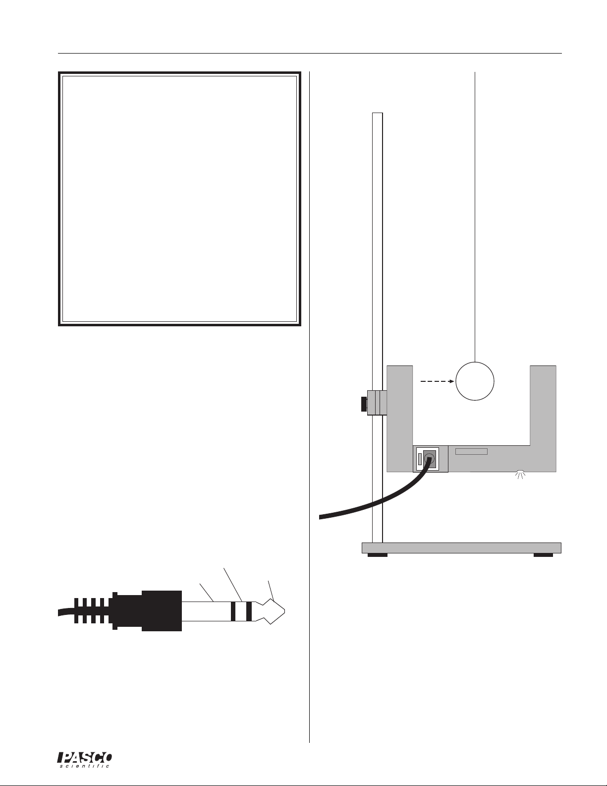
Clamp the Photogate Head to the support rod.
Position the photogate so the object to be timed will
pass through the photogate, blocking the beam. (See
Figure “Photogate with Pendulum”). To minimize
parallax error, pass the object as close to the detector
as possible, with the line of travel perpendicular to the
beam. Loosen the clamp screw to change the angle or
height of the photogate.
Plug the RJ12 phone plug from the cable assembly
into the modular phone jack on the photogate housing.
Plug the stereo phone plug at the other end of the
cable assembly into the timer, adapter cable, or interface.
Test the operation of the photogate by watching the
LED when the beam is blocked.
stereo
phone plug
(to timer)
RJ12 phone plug
(to modular phone
jack on photogate)
small rod
clamp
Photogate
LED: ON when
beam is blocked
Head
®
PHOTOGATE HEAD
emitter
ASSEMBLY NO.003-06268
detector
Photogate
Head
IDS mounting
bracket
1/4”dia
support rod
base
Accessory Photogate
2
®
Page 3
012-06375A Accessory Photogate
NOTES:
• The actual length of an object passing through
the photogate may be slightly different than the
effective length seen by the photogate. To determine the effective length, push the object
through the photogate, and measure the distance
moved by the object from where the LED first
comes ON to where it goes off. Use this effective length, rather than the actual length, in calculations. For example, if you were measuring
the speed of the object, you would divide the
effective length by the time during which the
object blocked the photogate beam.
• A stereo phone plug extension cord, such as
PASCO Model PI-8117, will increase the separation between the photogate and the timer.
Experiments
Refer to the experiment guide that comes with your
PASCO equipment (e.g., Introductory Dynamics System).
Photogate Specifications
Detector rise time: < 500 ns
Detector fall time: < 50 ns
Parallax error: For an object passing within 1 cm of the
detector, with a velocity less than 10 m/s, the difference
between the true and effective length is less than 1 mm.
Power requirements: 5 VDC ± 5% at 45 mA.
Infrared source: Peak at 880 nm.
Signal
GND
+5VDC
Photogate with Pendulum
Stereo Phone Plug
®
3
Page 4

Accessory Photogate 012-06375A
Limited Warranty
PASCO scientific warrants the product to be free from
defects in materials and workmanship for a period of one
year from the date of shipment to the customer. PASCO
will repair or replace, at its option, any part of the product
which is deemed to be defective in material or workmanship. The warranty does not cover damage to the product
caused by abuse or improper use. Determination of
whether a product failure is the result of a manufacturing
defect or improper use by the customer shall be made
solely by PASCO scientific. Responsibility for the return
of equipment for warranty repair belongs to the customer.
Equipment must be properly packed to prevent damage
and shipped postage or freight prepaid. (Damage caused
by improper packing of the equipment for return shipment will not be covered by the warranty.) Shipping costs
for returning the equipment, after repair, will be paid by
PASCO scientific.
Feedback
If you have any comments about the product or manual,
please let us know. If you have any suggestions on alternate experiments or find a problem in the manual, please
tell us. PASCO appreciates any customer feedback. Your
input helps us evaluate and improve our product.
To Reach PASCO
For technical support, call us at 1-800-772-8700 (toll-free
within the U.S.) or (916) 786-3800.
fax: (916) 786-3292
e-mail: techsupp@pasco.com
web: www.pasco.com
4
®
 Loading...