

Page 1
Instruction Manual and
Experiment Guide for
the PASCO scientific
Model ME-8960
DEMONSTRATION
GYROSCOPE
012-05327B
4/94
ME-8960
DEMONSTRATION
GYROSCOPE
© 1994 PASCO scientific $10.00
10101 Foothills Blvd. • P.O. Box 619011 • Roseville, CA 95678-9011 USA
Phone (916) 786-3800 • FAX (916) 786-8905 • TWX 910-383-2040
better
ways to
teach physics
Page 2

Page 3

012-05327B Demonstration Gyroscope
T able of Contents
Section Page
Copyright, Warranty, and Equipment Return..................................................ii
Introduction .....................................................................................................1
Equipment........................................................................................................2
Assembly
ME-8960 Demonstration Gyroscope.........................................................3
ME-8961 Additional Gyroscope Disk....................................................... 5
Experiments
Experiment 1: Precession ....................................................................7
Experiment 2: Counter-rotating Disks - Demonstration.....................13
Experiment 3: Precession - Demonstration ........................................15
Experiment 4: Nutations - Demonstration..........................................17
Technical Support................................................................................. Back Cover
i
Page 4
Demonstration Gyroscope 012-05327B
Copyright, Warranty and Equipment Return
Please—Feel free to duplicate this manual
subject to the copyright restrictions below.
Copyright Notice
The PASCO scientific Model ME-8960 Demonstration
Gyroscope manual is copyrighted and all rights reserved.
However, permission is granted to non-profit educational
institutions for reproduction of any part of this manual
providing the reproductions are used only for their
laboratories and are not sold for profit. Reproduction
under any other circumstances, without the written
consent of PASCO scientific, is prohibited.
Limited Warranty
PASCO scientific warrants this product to be free from
defects in materials and workmanship for a period of one
year from the date of shipment to the customer. PASCO
will repair or replace, at its option, any part of the product
which is deemed to be defective in material or workmanship. This warranty does not cover damage to the product
caused by abuse or improper use. Determination of
whether a product failure is the result of a manufacturing
defect or improper use by the customer shall be made
solely by PASCO scientific. Responsibility for the return
of equipment for warranty repair belongs to the customer.
Equipment must be properly packed to prevent damage
and shipped postage or freight prepaid. (Damage caused
by improper packing of the equipment for return shipment will not be covered by the warranty.) Shipping
costs for returning the equipment, after repair, will be
paid by PASCO scientific.
Equipment Return
Should this product have to be returned to PASCO
scientific, for whatever reason, notify PASCO scientific
by letter or phone BEFORE returning the product. Upon
notification, the return authorization and shipping instructions will be promptly issued.
➤ NOTE: NO EQUIPMENT WILL BE AC-
CEPTED FOR RETURN WITHOUT AN AUTHORIZATION.
When returning equipment for repair, the units must be
packed properly. Carriers will not accept responsibility
for damage caused by improper packing. To be certain
the unit will not be damaged in shipment, observe the
following rules:
➀ The carton must be strong enough for the item
shipped.
➁ Make certain there is at least two inches of packing
material between any point on the apparatus and the
inside walls of the carton.
➂ Make certain that the packing material can not shift in
the box, or become compressed, thus letting the instrument come in contact with the edge of the box.
Address: PASCO scientific
10101 Foothills Blvd.
Credits
This manual authored by: Jon Hanks
This manual edited by: Jon Hanks
P.O. Box 619011
Roseville, CA 95678-9011
Phone: (916) 786-3800
FAX: (916) 786-8905
ii
Page 5

012-05327B Demonstration Gyroscope
Introduction
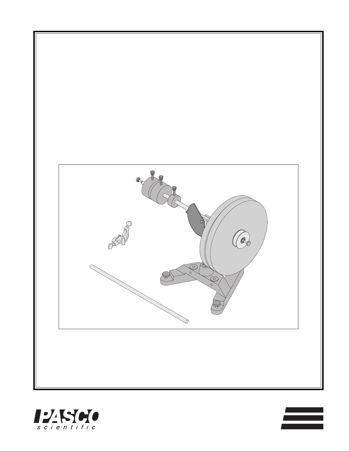
The PASCO ME-8960 Gyroscope has an open design
that makes all the parts easily accessible to the student.
The gyroscope consists of a disk that can be rotated by
hand or by pulling a string that is wrapped around the
pulley. A movable counterweight balances the disk.
The small counterweight is used to make fine adjustments to the balance. An add-on mass can be easily
placed on the end of the shaft to cause a torque and
precession. The rotational inertia of the disk is easily
obtained by accelerating the disk using a string around
the pulley that is attached to the disk.
1
Page 6
Demonstration Gyroscope 012-05327B
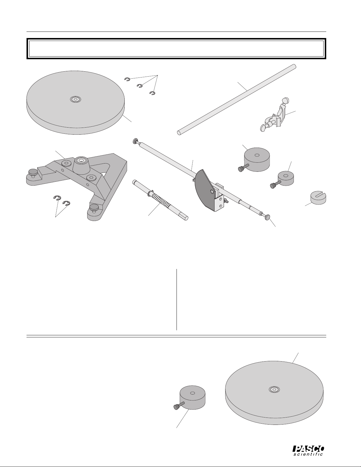
Equipment
cast iron
“A” base
“E” rings (2,
one extra
for rotating
axle)
rotating disk
rotating axle
“E” rings (3,
one extra for
rotating disk)
gyroscope
axle
ME-8960
DEMONSTRATION
GYROSCOPE
45 cm
support rod
right angle
rod clamp
900g
counterweight
30g
counterweight
150g add-
on mass
thumbscrews (2)
ME-8960 Demonstration Gyroscope Equipment
The ME-8960 Demonstration Gyroscope includes
the following:
– PASCO cast iron “A” base with rotating shaft
– axle (48 cm long) with pivot block, protractor
plate, and pointer
– one 900g large counterweight
– one 30g small counterweight
– one 150g add-on mass
The ME-8961 Additional Gyroscope Disk includes
the following:
– 25cm diameter rotating disk with pulley
– one 900g large counterweight
– 25cm diameter rotating disk with pulley
– 45 cm support rod
– right angle rod clamp
– extra “E” rings to secure rotating shaft and rotat-
ing disk
– two thumbscrews
rotating disk
900g
counterweight
2
ME-8961 Additional Gyroscope Disk
Page 7
012-05327B Demonstration Gyroscope
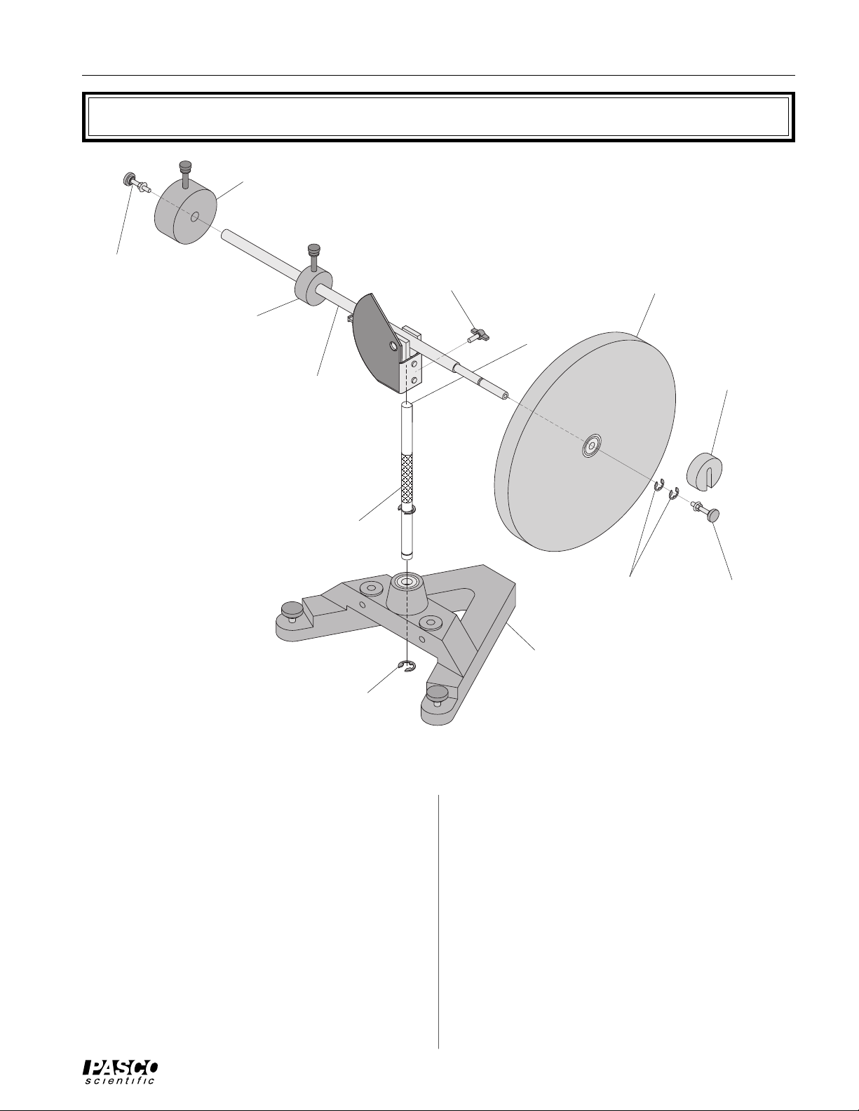
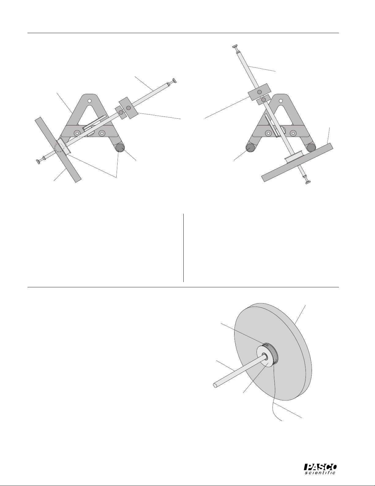
Assembly
900g
counterweight
thumbscrew
thumbscrew
rotating disk
30g
counterweight
gyroscope axle
rotating axle
“E” ring for
rotating axle
ME-8960
DEMONSTRATION
GYROSCOPE
flat of
rotating axle
cast iron “A” base
“E” rings (2) for
rotating disk
add-on mass
thumbscrew
Figure 1: Demonstration Gyroscope Assembly
ME-8960 Demonstration Gyroscope
Assembling the Demonstration Gyroscope
➀ Insert the cylindrical end of the vertical shaft into
the bearings on the top-side of the A-shaped iron
base. Secure the shaft in place by inserting the re-
taining ring in the slot at the bottom of the shaft.
See Figure 1.
➁ Attach the gyroscope axle to the vertical shaft and
tighten the thumb screw against the flat side of the
“D” on the vertical shaft.
➂ Slide the smaller of the two counterweights (30g)
onto the long side of the gyroscope axle and tighten
the thumbscrew. Then slide the larger of the two
counterweights (900g) onto the same end of the
shaft and tighten its thumbscrew.
➃ Put the disk on the other end of the gyroscope axle
with the pulley side of the disk facing the center of
the gyro. Secure the disk in place with the retaining
rings (2). See Figure 1.
➄ Screw the thumbscrew into the end of the shaft un-
til the nut is tight against the end of the shaft
3
Page 8
Demonstration Gyroscope 012-05327B
gyroscope axle
gyroscope axle
“A” base
(rotated 90˚)
adjust this foot first
rotating
disk
leveling feet
Figure 2: Leveling the Base
Leveling the Base
➀ Purposely make the apparatus unbalanced by mov-
ing the 900g counterweight towards the center.
➁ Adjust the leveling foot on one of the legs of the
base until the gyroscope disk is aligned over the
leveling foot on the other leg of the base. See Figure 2.
900g
counterweight
then adjust this foot
➂ Rotate the gyroscope 90 degrees so the gyroscope
axle is parallel to one side of the “A” and adjust the
other leveling foot until the shaft will stay in this
position. See Figure 2.
➃ Adjust the position of the 900g counterweight until
the gyroscope is balanced without the add-on mass.
The 30g counterweight can be used to fine tune the
balance.
rotating
disk
Using the Rotating Disk Pulley
➀ Make sure the rotating disk is secure on the gyro-
scope axle and decide which direction you want the
disk to rotate.
➁ Tie a loop in the end of a length of thread (approxi-
mately 1.5 meters long) and put the loop around the
dowel pin located on the surface of the rotating disk
pulley and wind the thread around the surface of
the pulley. See Figure 3.
➂ Holding the gyroscope axle in place, pull the thread
to rotate the disk at the desired speed.
rotating disk
dowel pin
gyroscope
axle
pulley
thread
Figure 3: Using the Rotating Disk Pulley
4
Page 9

012-05327B Demonstration Gyroscope
included 900g
counterweight
additional
gyroscope axle
(part of ME-8960)
Demonstration
ME-8960
Gyroscope
ME-8960
DEMONSTRATION
GYROSCOPE
gyroscope disk
add-on mass
(part of ME-8960)
Figure 4: Using the Additional Gyroscope Disk
ME-8961 Additional Gyroscope Disk
Using the Additional Gyroscope Disk
➀ Slide the included 900g counterweight onto the
long side of the gyroscope axle and tighten the
thumbscrew.
thumbscrew (part of
ME-8960)
➁ Put the Additional Gyroscope Disk on the other end
of the gyroscope axle with the pulley side of the
disk facing away from the center of the gyroscope
apparatus. Secure the disk in place with the supplied thumbscrew. See Figure 4.
5
Page 10

Demonstration Gyroscope 012-05327B
Notes:
6
Page 11

012-05327B Demonstration Gyroscope
dt
d
φ
dt
Experiment 1: Precession
EQUIPMENT NEEDED
– Gyroscope (ME-8960) – meter stick
– stopwatch (SE-8702) – table clamp for pulley
– Super Pulley (ME-9450) – thread (1.5 meters)
– Pulley Mounting Rod (SA-9242) – computer (optional)
– Mass and Hanger Set (ME-9348) – Smart Pulley (optional)
– balance – Smart Pulley software (optional)
Purpose
The purpose of this experiment is to measure the precession rate of a gyroscope and compare it to the theoretical value.
Theory
A torque is applied to the gyroscope by hanging a mass on the end of the shaft. This torque
causes the gyroscope to precess at a certain angular speed, Ω.
Assume that the gyroscope is initially balanced in the horizontal position, θ = 90˚. The disk
is spun at an angular speed (ω) and then a mass, m, is attached to the end of the gyroscope
shaft at a distance, d, from the axis of rotation. This causes a torque: τ = mgd. But the
torque is also equal to dL/dt, where L is the angular momentum of the disk. As shown in
Figure 1.1, for small changes in angle, dφ, dL = L dφ.
dφ
→
L
130
120
110
100
90
80
70
60
50
side view
d
ω
140
CAUTION
MAGNET
ME-8960
DEMONSTRATION
GYROSCOPE
40
30
mg
top view
Figure 1.1: Torque Applied to Horizontal Gyroscope
dL
→
→
L
Substituting for dL in the torque equation gives
τ
= mgd =
dL
= L
7
Page 12

Demonstration Gyroscope 012-05327B
Ω
ω
τ
α
F
Since dφ/dt = Ω, the precession speed,
mgd = L
and the precession rate is given by
mgd
Ω
=
I
where I is the rotational inertia of the disk and ω is the angular speed of the disk.
To find the rotational inertia of the disk experimentally, a known torque is applied to the
disk and the resulting angular acceleration is measured. Since τ = Iα,
I =
where α is the angular acceleration which is equal to a/r and τ is the torque caused by the
weight hanging from the thread which is wrapped around the pulley on the disk.
τ
= r
where r is the radius of the pulley about which the thread is wound and F is the tension in
the thread when the disk is rotating.
Applying Newton’s Second Law for the hanging mass, m, gives (See Figure 1.2)
Σ
F = mg – F = ma
F
pulley
hanging
mass
rotating disk
mg
Figure 1.2: Rotating Disk and Free-Body Diagram
α
Solving for the tension in the thread gives
F = m (g – a)
8
Page 13

012-05327B Demonstration Gyroscope
So, once the linear acceleration of the mass (m) is determined, the torque and the angular
acceleration can be obtained for the calculation of the rotational inertia. The acceleration is
obtained by timing the fall of the hanging mass as it falls from rest a certain distance (y).
Then the acceleration is given by
2y
a =
2
t
Part I: Measuring the Precession Rate
Setup
➀ Level the gyroscope base as described on page 4 in the Assembly section of this manual.
➁ Adjust the position of the large counterweight until the gyroscope is balanced without the
add-on mass. The small counterweight can be used to fine-tune the balance.
Procedure
➀ Weigh the add-on mass and record its mass in Table 1.1. Attach the add-on mass to the end
of the shaft. Measure the distance (d) from the axis of rotation to the center of the add-on
mass. Record this distance in Table 1.1
➁ While holding the gyroscope so it can’t precess, spin the disk at about two revolutions per
second. Time 10 revolutions of the disk to determine the angular speed (ω) of the disk.
Record in Table 1.1.
➂ Let the gyroscope precess and time two revolutions to find the precession rate. Record in
Table 1.1.
➃ Immediately repeat the measurement of 10 revolutions of the disk. The before-and-after
Table 1.1: Angular Speed Measurements
Add-On Mass
Distance (d)
Time for 10 Revolutions (initial)
Time for Precession
Time for 10 Revolutions (final)
data will be used to find the average angular speed of the disk during the precession.
9
Page 14

Demonstration Gyroscope 012-05327B
Part II: Measuring Quantities For the Theoretical Value
Setup
➀ Clamp the gyroscope shaft in the horizontal position. See Figure 1.3.
➁ Attach a Super Pulley with rod to the table using a table clamp.
➂ Wind a thread around the pulley on the center shaft and pass the thread over the Super
Pulley.
right angle rod
clamp
140
130
120
110
100
CAUTION
MAGNET
90
80
70
60
ME-8960
DEMONSTRATION
50
GYROSCOPE
40
30
rotating disk
support rod
Figure 1.3: Experiment Setup
Procedure
Accounting For Friction
Because friction is not included in the theory, it will be compensated for in this experiment
by finding out how much mass over the pulley it takes to overcome kinetic friction. When
the mass drops at a constant speed, the weight of the mass is equal to the kinetic friction.
Then this “friction mass” will be subtracted from the mass used to accelerate the apparatus.
➀ To find the mass required to overcome kinetic friction, put just enough mass hanging over
the pulley so that the velocity is constant. Record this friction mass in Table 1.2.
Finding the Acceleration of the Disk
➀ To find the acceleration, put about 30 g (record the exact hanging mass in Table 1.2) over
the pulley. Wind the thread up and let the mass fall from the table to the floor, timing the
fall.
➁ Repeat this for a total of 5 times, always starting the hanging mass in the same position.
➂ Measure the height that the mass falls and record this height in Table 1.2.
10
Page 15

012-05327B Demonstration Gyroscope
Alternate Computer Method:
If a computer and Smart Pulley are used, the acceleration of the disk can be obtained by
finding the slope of the velocity vs. time graph.
Measure the Radius
➀ Using calipers, measure the diameter of the pulley about which the thread is wrapped and
calculate the radius. Record the radius in Table 1.2.
Table 1.2 Rotational Inertia Data
Friction Mass
Hanging Mass
Height Mass Falls
Radius of Pulley
Times
Average:
Analysis
➀ Using the average time from Table 1.2, calculate the acceleration and record the result in
Table 1.3.
➁ Calculate the rotational inertia:
(a) Subtract the “friction mass” from the hanging mass used to accelerate the disk to
determine the mass, m, to be used in the equations.
(b) Calculate the experimental value of the rotational inertia and record it in Table 1.3.
➂ Using the times for 10 revolutions in Table 1.1, divide by 10 to find the periods. Average
these two periods and calculate the average angular speed (ω = 2π/T). Record the angular
speed in Table 1.3.
➃ Find the experimental value for the precession rate by dividing the precession time by two
and calculating Ω = 2π/T. Record in Table 1.3.
➄ Calculate the theoretical value for the precession rate and record in Table 1.3.
➅ Calculate the percent difference between the experimental and theoretical values of the
precession rate.
11
Page 16

Demonstration Gyroscope 012-05327B
Table 1.3: Results
Acceleration
Rotational Inertia
Average Angular Speed of Disk
Experimental Precession Rate
Theoretical Precession Rate
% Difference
Questions
➀ What happens to the direction of precession if the spin of the disk is reversed?
➁ How does the rate of precession change if the angular speed of the disk is increased?
12
Page 17

012-05327B Demonstration Gyroscope
Experiment 2: Counter-rotating Disks
- Demonstration
EQUIPMENT NEEDED
– Gyroscope (ME-8960)
– Accessory Disk and Extra Counterweight (ME-8961)
– Physics String (SE-8050)
Purpose
It is shown that two disks spinning in opposite directions at the same angular speed will not
precess when a torque is applied.
Setup
➀ Remove the screw in the end of the shaft and slide the second disk onto the shaft with the
pulley side facing away from the first disk. Secure the second disk by tightening the screw
in the end of the shaft. See Figure 2.1.
➁ Put the second counterweight on the other end of the shaft and slide the counterweights
until the gyroscope is balanced. Spin the disks and check the balance by seeing if the
gyroscope precesses. If it precesses, the balance needs further adjustment.
➂ Cut two pieces of string, each 1 meter long. Tie one end of each string to the ends of a pen.
The pen will be used to pull the two strings simultaneously. Tie a loop in the other end of
each string to hook over the dowel pins.
➃ To make the direction of rotation more visible to the students, stick a white paper dot on the
edge of each disk.
rotating disk (part of
additional 900g
counterweight (part
of ME-8961)
900g counterweight
(part of ME-8960)
“A” base
ME-8960)
140
130
120
110
100
CAUTION
MAGNET
90
80
70
60
ME-8960
DEMONSTRATION
50
GYROSCOPE
40
30
add-on mass
additional rotating disk
(part of ME-8961)
Figure 2.1: Counter-rotating disks
13
Page 18

Demonstration Gyroscope 012-05327B
Procedure
➀ Use your hand to spin both disks in the same direction. Show that the gyroscope does not
precess.
➁ Put the add-on mass on the end of the shaft and secure with a screw. Spin both disks in the
same direction and show that the gyroscope now precesses.
➂ Stop the disks and reverse the spin of both disks to show that the gyroscope now precesses
in the opposite direction.
➃ Now counter-rotate the disks. To do this, wrap an equal number of turns of string in oppo-
site directions around the pulleys on each of the disks. Pull on both strings simultaneously
using the pen as a handle. Point out that even though a torque is still being applied to the
gyro, the gyroscope does not precess when the two disks are spinning in opposite directions.
14
Page 19

012-05327B Demonstration Gyroscope
Experiment 3: Precession - Demonstration
EQUIPMENT NEEDED
– Gyroscope (ME-8960)
Purpose
It is shown that if a precessing gyroscope is restricted from precessing, the disk will fall.
See Figure 3.1.
rotating disk
140
130
120
110
100
CAUTION
MAGNET
90
80
70
60
ME-8960
DEMONSTRATION
50
GYROSCOPE
40
30
add-on mass
counterweights
rotating
axle
Figure 3.1: Precession
Procedure
➀ Adjust the counterweights until the gyroscope is balanced.
➁ Put the add-on mass on the end of the shaft.
➂ Spin the disk and allow the gyroscope to precess.
“A” base
rotating
axle
100
90
80
130
120
110
70
60
50
140
CAUTION
MAGNET
ME-8960
DEMONSTRATION
GYROSCOPE
40
30
rotating disk
➃ Slow or stop the precession by grabbing the center vertical shaft with your hand. As you do
so, the disk will fall.
➄ You can also cause the disk to rise by spinning the center vertical shaft in the same direc-
tion as the precession.
15
Page 20

Demonstration Gyroscope 012-05327B
Notes:
16
Page 21

012-05327B Demonstration Gyroscope
Experiment 4: Nutations - Demonstration
EQUIPMENT NEEDED
– Gyroscope (ME-8960)
Purpose
Three different types of nutation are shown.
Procedure
➀ Adjust the counterweights until the gyroscope is balanced.
➁ Put the add-on mass on the end of the shaft.
➂ Spin the disk and release the gyroscope from rest at an angle of about 30˚. See Figure 4.1.
rotating disk
140
counterweights
110
100
90
80
70
130
120
60
DEMONSTRATION
50
40
CAUTION
MAGNET
ME-8960
GYROSCOPE
30
add-on mass
rotating
axle
“A” base
Figure 4.1: Release Position of Gyro
➃ The resulting nutation will look like pattern (A) in Figure 4.2.
➄ Stop the precession and spin the disk again. Release the gyroscope from the same angle but
give it an initial push in the direction of precession. The resulting nutation will look like
pattern (B) in Figure 4.2.
➅ Stop the precession and spin the disk again. Release the gyroscope from the same angle but
give it an initial push in the direction opposite to the precession. The resulting nutation will
look like pattern (C) in Figure 4.2.
➆ Spin the disk at a different speed and check the effect this has on the speed of the nutation.
➇ Release the disk from a different angle and check the effect this has on the nutation.
17
Page 22

Demonstration Gyroscope 012-05327B
(A) Released from rest
(B) Released with
forward speed
Figure 4.2: Patterns of Resultant Nutations
(C) Released with
backward speed
18
Page 23

012-05327B Demonstration Gyroscope
T echnical Support
Feed-Back
If you have any comments about this product or this
manual please let us know. If you have any suggestions on alternate experiments or find a problem in the
manual please tell us. PASCO appreciates any customer feed-back. Your input helps us evaluate and
improve our product.
To Reach PASCO
For Technical Support call us at 1-800-772-8700 (tollfree within the U.S.) or (916) 786-3800.
Contacting Technical Support
Before you call the PASCO Technical Support staff it
would be helpful to prepare the following information:
• If your problem is computer/software related, note:
Title and Revision Date of software.
Type of Computer (Make, Model, Speed).
Type of external Cables/Peripherals.
• If your problem is with the PASCO apparatus, note:
Title and Model number (usually listed on the label).
Approximate age of apparatus.
A detailed description of the problem/sequence of
events. (In case you can't call PASCO right away,
you won't lose valuable data.)
If possible, have the apparatus within reach when
calling. This makes descriptions of individual parts
much easier.
• If your problem relates to the instruction manual,
note:
Part number and Revision (listed by month and year
on the front cover).
Have the manual at hand to discuss your questions.
19
Page 24

 Loading...