

Page 1
012-05293F Complete Rotational System
Instruction Manual and
012-05293F
01/09
Experiment Guide for the
PASCO scientific Model
ME-8950A
COMPLETE ROTATIONAL
SYSTEM
IA
T
R
E
Y
IN
R
L
O
A
S
N
S
IO
E
T
C
A
C
T
A
O
R
R
A
O
I
T
T
A
R
T
E
I
O
I
N
L
N
A
A
Y
C
R
C
O
S
E
S
© PASCO scientific www.pasco.com
®
Page 2

Complete Rotational System 012-05293F
Page 3

012-05293F Complete Rotational System
Table of Contents
Section Page
Copyright Warranty, and Equipment Return................................................... ii
Introduction...................................................................................................... 1
• Description
• About this Manual
• Computer Timing
Equipment ....................................................................................................... 2
Miscellaneous Supplies ................................................................................... 3
Assembly
ME-8951 Rotating Platform ......................................................................4
ME-8952 Centripetal Force Accessory ..................................................... 6
ME-8953 Rotational Inertia Accessory ..................................................... 8
Experiments Using the ME-8951 Rotating Platform
Exp 1 Conservation of Angular Momentun (Projectile Version)........ 9
Exp 2 Rotational Inertia of a Point Mass............................................ 15
Experiments Using the ME-8952 Centripetal Force Accesory
Exp 3 Centripetal Force...................................................................... 19
Exp 4 Conservation of Angular Momentum Using Point Mass.........25
Experiments Using the ME-8953 Rotational Inertia Accessory
Exp 5 Rotational Inertia of Disk and Ring ......................................... 31
Exp 6 Rotational Inertia of Disk Off-Axis (Fixed/Rotating).............. 37
Exp 7 Conservation of Angular Momentum Using Disk and Ring.... 41
Technical Support........................................................................................... 45
i
Page 4

Complete Rotational System 012-05293F
Copyright, Warranty and Equipment Return
Please—Feel free to duplicate this manual
subject to the copyright restrictions below.
Copyright Notice
The PASCO scientific Model ME-8950A Complete
Rotational System manual is copy right ed and all rig hts
reserved. However, per mis si on i s gr anted to non-profit
educational institutions for reproduction of any part of
this manual providing the reproductions are used only
for their laboratories and are not sold for profit. Reproduction under any other circumstances, wi thout the written consent of PASCO scientific, is prohibited.
Limited Warranty
PASCO scientific warrant s thi s produc t to be fre e from
defects in material s and workmanship for a period o f one
year from the date of shipment to the customer. PASCO
will repair or replace, at its opti on, any part of the product
which is deemed to be defecti ve in material or workmanship. This warranty does not cov er damage to the product
caused by abuse or improper use. Determination of
whether a product failur e is the result of a manufacturing
defect or improper use by the customer shall be made
solely by PASCO scientif ic. Responsibility for the retur n
of equipment for warranty repair belongs to the customer. Equipment must be properly packed to prevent
damage and shipped postage or freight prepaid. (Damage
caused by improp er packing of the equipment fo r return
shipment will not be covered by the war ranty.) Shipping
costs for returning the eq uipment, after repair, will be
paid by PASCO scientific.
Equipment Return
Should this product have to be returned to PASCO scientific, for whate ver reason, not ify PASCO scientifi c by
letter or phone BEFORE returning the product. Upon
notification, the return authorization and shipping
instructions will be promptly issued.
NOTE: NO EQUIPMENT WILL BE
ACCEPTED FOR RETURN WITHOUT AN
AUTHORIZATION.
When returning equipment for repair, the units must be
packed properly. Carriers will not accept responsibility
for damage caused by improper packing. To be certain
the unit will not be damaged in shipment, observe the
following ru les:
1. The carton must be strong enough for the item
shipped.
2. Make certain there is at least two inches of packing
material between any poi nt on the appa rat us and the
inside walls of the carton.
3. Make cer tain that the packing material can not shift
in the box, or become co mpressed, thus letting the
instrument come in contact wit h th e edge of the box.
Address:PASCO scientific
10101 Foothills Blvd.
P.O. Box 619011
Credits
This manual authored by: Ann and Jon Hanks
This manual edited by: Ann and Jon Hanks
Roseville, CA 95678-9011
Phone: (916) 786-3800
FAX: (916) 786-8905
email: techsupp@pasco.com
web: www.pasco.com
ii
Page 5

012-05293F Complete Rotational System
Introduction
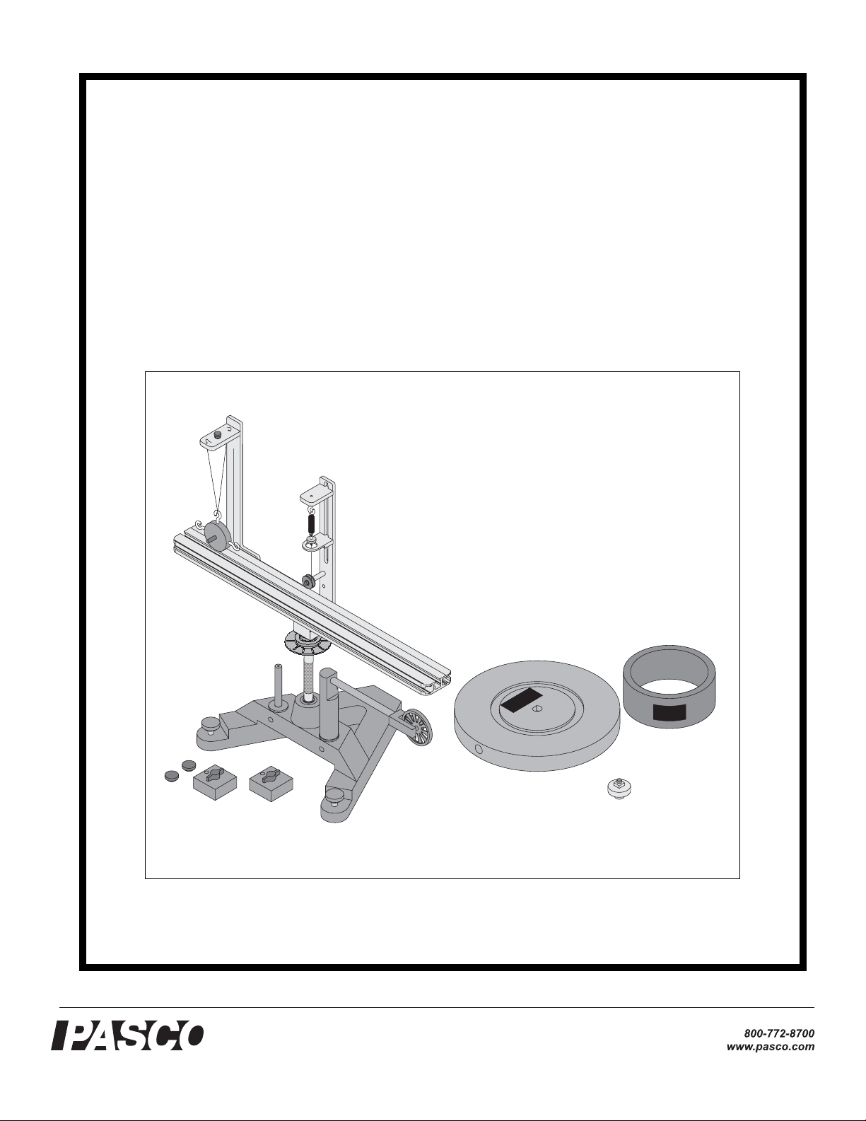
PASCO’s Complete Rotational System provides a full
range of experiments in centripetal force and rotational
dynamics. The system consists of three separate components:
Description
The ME-8951 Rotating Platform consists of a sturdy 4
kg base with low friction bearings and a rotating arm
which serves as a versatile base for rotation experiments.
This platform is a general purpose base upon which you
may mount anything (having a mass under 3 kg) you wish
to rotate. The T-slots in the track supply a convenient
way to mount objects to the track using thumbscrews and
square nuts. To use the Centripetal Force Accessory (ME-
8952) or the Rotational Inertia Accessory (ME-8953),
each must be mounted on this base. A photogate/pulley
mount and two 300 g masses are also included.
The ME-8952 Centripetal Force Accessory is comprised
of two vertical posts which can be mounted to the Rotating Platform with thumbscrews. These posts are adjustable and can be positioned virtually anywhere along the
length of the platform. The radius indicator is at the center
of the apparatus so it can be clearly seen while the
apparatus is rotating. This accessory requires the Rotating
Platform (ME-8951) to operate. The PASCO Centripetal
Force Accessory can be used to experiment with centripetal force and conservation of angular momentum. For
the centripetal force experiments it is possible to vary the
mass and radius to see the resulting change in the centripetal force. The force can also be held constant while
other quantities are varied. The Centripetal Force Accessory is powered by hand and the rate of rotation can be
counted manually or read by a computer. Variable hanging masses are included.
The ME-8953 Rotational Inertia Accessory includes a
disk and a metal ring. The disk can be mounted to the
rotating base in a variety of positions and at any radius.
This accessory requires the Rotating Platform (ME-8951)
to operate. The Rotational Inertia Accessory allows you
to perform rotational inertia experiments and conservation of angular momentum experiments.
About This Manual
The following Equipment section describes each component in detail and the subsequent Assembly section provides instructions for component assembly and setup.
The Experiment section contains several experiments
that can illustrate some of the basic theory of centripetal
force, rotational inertia, etc.
Computer Timing
You can use a PASCO computer interface with a PASCO
Photogate Head to measure the motion of the apparatus.
Some of the experiments describe how to use DataStudio,
the software program that supports every PASCO computer interface.
If you are using a computer interface such as a Science-
Workshop 750 or ScienceWorkshop 500, you can connect
the cable of the Photogate Head directly into the interface.
If you are using a PASPORT interface such as a USB
Link, PowerLink, Xplorer, or Xplorer GLX, you will
need to use a PASPORT Digital Adapter (PS-2159) to
connect the Photogate Head to the interface.
See the PASCO web site at www.pasco.com for more
information on PASCO interfaces, sensors, and software.
1
Page 6
Complete Rotational System 012-05293F
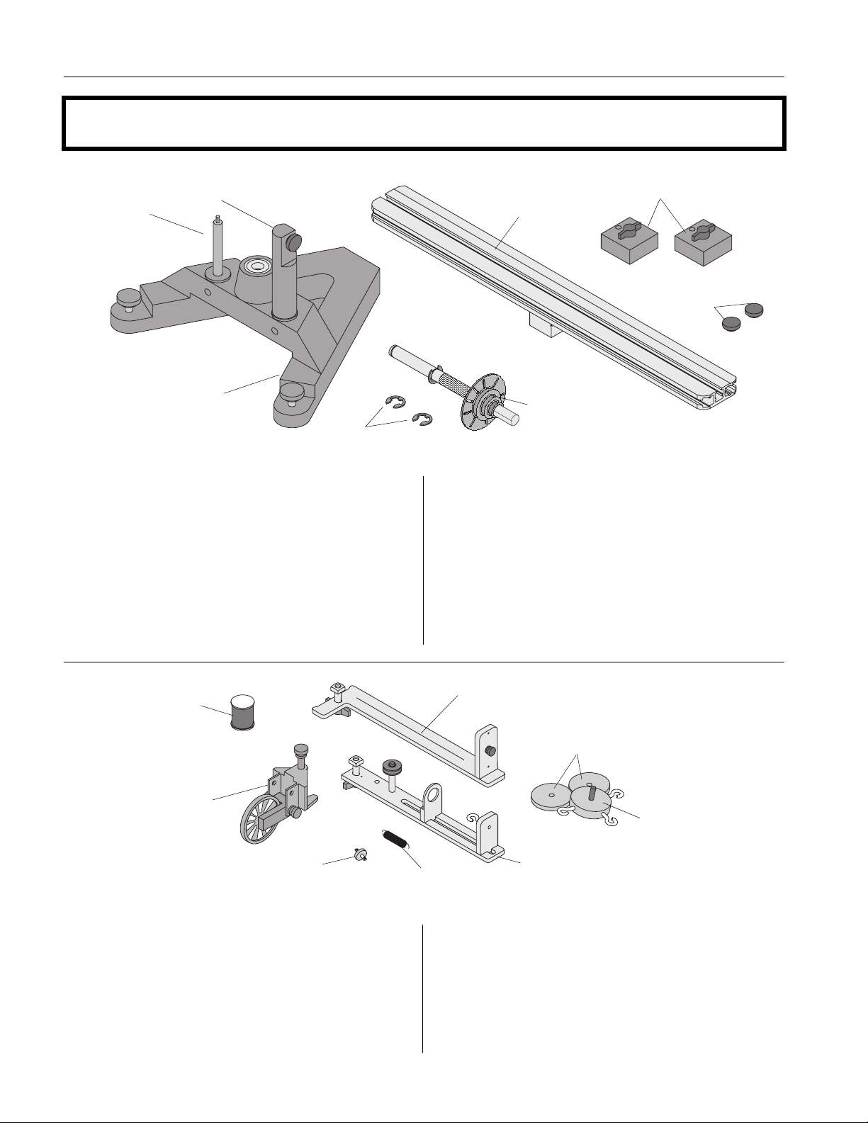
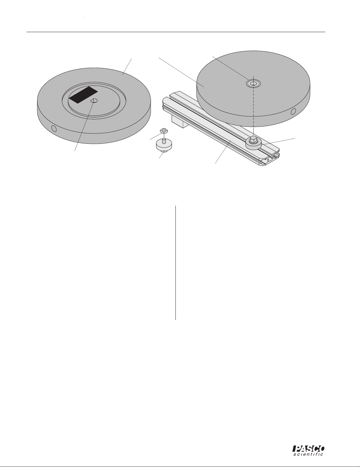
Equipment
300g square mass (2)
with thumbscrews and
square nuts
low-profile thumb-
screw assemblies (2)
photogate
mounting rod
accessory
mounting rod
aluminum rotating
platform
cast iron "A" base
"E" rings (2, 1 extra)
ME-8951 Rotating Platform Equipment
The ME-8951 Rotating Platform includes the following:
- PASCO cast iron “A” base with rotating shaft and
pulley with 10 holes
- aluminum track
- two square masses (about 300 g) with thumb screw
and square nut
spool of thread
clamp-on
pulley
rotating vertical shaft
with 10-hole pulley
- two additional low-profile screws and square nuts
to act as stops for the square mass in the Conservation of Angular Momentum experiment
- accessory mounting rod for mounting a 10-spoke
pulley with or without the optional PASCO Photogate Head
- photogate mounting rod for mounting a PASCO
Photogate Head (ME-9498A)
side post
50g masses (2)
100g mass with 3 open
hooks
plastic
indicator disk
ME-8952 Centripetal Force Accessory Equipment
The ME-8952 Centripetal Force Accessory includes:
- center post that supports an indicator mechanism
which consists of a small pulley, a movable spring
holder, a movable indicator, a spring, and a plastic
indicator disk
spring
center post
- side post for hanging hooked mass
- mass (100 g) with 3 open hooks
- 2 additional 50 gram masses
- clamp-on pulley
- 1 spool of thread
2
Page 7
012-05293F Complete Rotational System
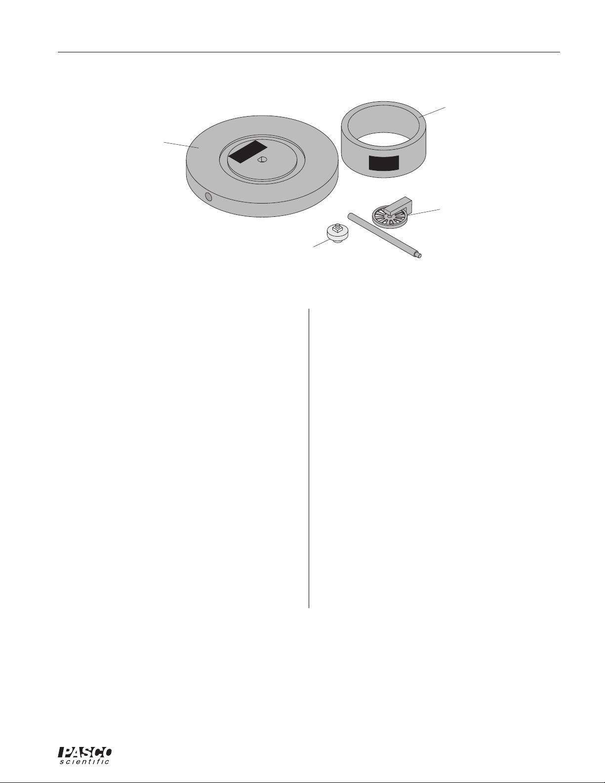
mass ring
(12.7 cm outside
diameter)
rotational disk
(25.4 cm diameter)
ACCESSORY
ROTATIONAL INERTIA
R
A
O
I
T
T
A
R
T
E
I
O
I
N
L
N
A
A
Y
C
R
C
O
S
E
S
Super Pulley and rod
rotating platform
adapter
ME-8953 Rotational Inertia Accessory Equipment
The ME-8953 Rotational Inertia Accessory includes:
- disk with bearings in the center
- ring (12.7 cm diameter)
- adapter to connect disk to platform
- 10-spoke pulley and rod
Other Equipment Needed:
The following is a list of equipment recommended for the
experiments described in this manual. See the PASCO
catalog for more information.
- Projectile Launcher
- Projectile Collision Accessory
- Photogate Head (and a compatible PASCO computer interface)
- Mass and Hanger Set
- Stopwatch
- String
- Balance (for measuring mass)
- Calipers
-Meter Stick
Miscellaneous Supplies:
- graph paper
- carbon paper
- white paper
- rubber bands
- paper clips
Compatible PASCO Computer Interfaces:
The Photogate Head connects directly to a
ScienceWorkshop interface (such as the
ScienceWorkshop 500), and connects through a Digital
Adapter (PS-2159) to a PASPORT interface (such as a
USB Link, PowerLink, Xplorer, or Xplorer GLX).
3
Page 8

Complete Rotational System 012-05293F
Assembly
ME-8951 Rotating Platform
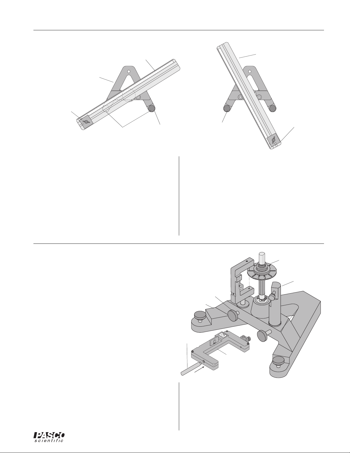
Assembling the Rotating Platform
1. Insert the cylindrical end of the shaft into the bearings
on the top-side of the A-shaped iron base. Secure the
shaft in place by inserting the "E" ring in the slot at
the bottom of the shaft. See Figure 1.
2. Mount the track to the shaft and tighten the thumb
screw against the flat side of the “D” on the shaft. See
Figure 1.
rotating platform
thumbscrew
flat of vertical shaft
vertical shaft
"A" base
"E" ring
Figure 1: Attaching the Vertical Shaft to the Base and Rotating Platform Assembly
4
Page 9
012-05293F Complete Rotational System
rotating plat-
form
20
191817161514131211 24232221
300g square
mass
Leveling the Base
"A" base
20
111213141516171819212224
leveling feet
010
123456789
10
987654321
adjust this foot
Figure 2: Leveling the Base
Some experiments (such as the Centripetal Force experiments) require the apparatus to be extremely level. If the
track is not level, the uneven performance will affect the
results. To level the base, perform the following steps:
1. Purposely make the apparatus unbalanced by attaching the 300 g square mass onto either end of the
aluminum track. Tighten the screw so the mass will
not slide. If the hooked mass is hanging from the side
post in the centripetal force accessory, place the
square mass on the same side.
2. Adjust the leveling screw on one of the legs of the
rotating platform
(rotated 90° as shown)
010
123456789
111213141516171819212224
20
first
20
191817161514131211 24232221
10
then adjust this
foot
987654321
base until the end of the track with the square mass is
aligned over the leveling screw on the other leg of the
base. See Figure 2.
3. Rotate the track 90 degrees so it is parallel to one side
of the “A” and adjust the other leveling screw until
the track will stay in this position.
4. The track is now level and it should remain at rest
regardless of its orientation.
300g square
mass
Using an Optional Photogate Head
The optional Photogate Head (ME-9498A) can be
mounted to the Rotating Platform in two ways:
• Photogate Mount Rod can be used to mount the
Photogate Head directly to the base as shown in
Figure 3.
• Accessory Mounting Rod can to be used to mount
a Pulley Mounting rod and a Super Pulley along
with the Photogate Head to the base in order to run
a string over the Super Pulley. See Figure 4.
To Mount the Photogate Head Only:
1. Mount the Photogate Head on the threaded end of the
photogate mount rod.
2. Remove the swivel clamp from the top of the Photogate Head.
3. Slide the non-threaded end of the photogate mount
rod into a hole in the A-base and clamp it in place with
the thumbscrew.
4. Adjust the Photogate Head so that its infrared beam
can be interrupted by the 10 spoke pulley on the
vertical shaft as the shaft turns.
10-spoke pulley
on vertical shaft
accessory
mounting rod
thumbscrew
"A" base
photogate
mount rod
Photogate Head
(optional)
Figure 3: Using the Photogate Mount Rod With the
Photogate Head
Make sure that the Photogate Head does not rub against
the 10 spoke pulley or any other part of the apparatus.
5. Connect the cable to the Photogate Head and a PASCO
interface.
5
Page 10

Complete Rotational System 012-05293F
6. When the Photogate Head is powered by a computer
interface, you can tell when the photogate is
blocked by watching the LED indicator on
the photogate.
10-spoke
pulley on
vertical
shaft
nylon thumb-
screw
To use the Super Pulley and Photogate Head
with the Pulley Mounting Rod:
1. Attach the Super Pulley -- and the Photogate
Head if needed -- to the Pulley Mounting
Rod.
2. Insert the pulley mounting rod into the hole
in the Accessory Mounting Rod and tighten
the thumb screw. See Figure 4.
accessory
mounting rod
3. Rotate the accessory mounting rod so that a
string from the pulley on the center shaft will
be aligned with the groove on the Super
"A" base
Pulley.
4. Adjust the position of the base so the string
passing over the Super Pulley will clear the
edge of the table.
Figure 4: Using the Accessory Mounting Rod With the Pulley
Mounting Rod, Super Pulley, and Photogate Head
pulley
mounting rod
Super Pulley
Photogate Head
(optional)
ME-8952 Centripetal Force Accessory
Center Post Assembly
Assemble the center post as shown in Figure 5:
1. Attach one end of the spring to the spring bracket and
connect the indicator disk to the other end of the
spring. Insert the spring bracket into the slot on the
center post and tighten the thumb screw.
2. Tie one end of a string (about 30 cm long) to the bottom
of the indicator disk and tie a loop in the other end of
the string.
3. Insert the indicator bracket into the slot on the center
post, placing it below the spring bracket. Tighten the
thumb screw.
4. Attach the pulley in the higher of the two holes on the
center bracket.
5. Insert the thumb screw at the bottom of the center post
and attach the square nut.
spring
bracket
spring
pulley
reference mark
(center of post)
square nut
Figure 5: Center Post Assembly
center
post
indicator
disk
indicator
bracket
thumbscrew
6
Page 11

012-05293F Complete Rotational System
holes for
thread
nylon thumbscrew
Side Post Assembly
Assemble the side post as shown in Figure 6:
1. Insert the thumb screw at the bottom of the side post
and attach the square nut.
single length
of thread
(30cm long)
side post
2. Using a string about 30 cm long, tie the string around
the screw head on the top of the side post. Then thread
the other end of the string down through one of the
holes in the top of the side post and then back up
through the other hole. Do not pull the string taut.
3. Loosen the screw on the top of the side post and wrap
100g mass
the loose end of the string around the threads of the
screw and tighten the screw.
square nut
Figure 6: Side Post Assembly
thumbscrew
Threading the Centripetal Force Accessory
1. Mount the center post in the T-slot on the side of the
track that has the rule. Align the line on the center post
with the zero mark on the rule and tighten the thumb
screw to secure it in place. Then mount the side post
on the same side of the track. See Figure 7.
2. Hang the 100 g mass from the string on the side post
and adjust the height of the mass so the string coming
from the center post will be level when the mass is
hanging straight down.
rotating
platform
100g mass
thread
zero mark
of rule
side post
indicator
disk
indicator
bracket
center post
pulley
5
4
3
2
1
0
1
2
reference mark
(center of post)
3
Figure 7: Threading the Centripetal Force Accessory
7
Page 12
Complete Rotational System 012-05293F
bearing of
"D" hole on top sur-
face of rotational
ACCESSORY
ROTATIONAL INERTIA
rotational disk
square
nut
platform
adapter
rotational disk
platform
adapter
rotating platform
Figure 8: Rotational Inertia Accessory Including Platform Adapter Assembly
ME-8953 Rotational Inertia Accessory
Rotational Inertia Accessory Assembly
Little assembly is required to use the Rotational Inertia
Accessory. The rotational disk can be placed directly onto
the axle of the rotating base or can be used with the
rotating platform via the included platform adapter.
Platform Adapter Assembly
1. Attach the square nut (supplied with the Rotational
Inertia Accessory) to the platform adapter.
2. Position the platform adapter at the desired radius as
shown in Figure 8.
3. Grip the knurled edge of the platform adapter and
tighten.
The rotating disk can be mounted in a variety of positions
using any of the four holes on the rotation disk.
• Two “D” holes exist on the edge of the disk, located
at 180° from one another.
• One “D” hole is located at the center on the top
surface (the surface with the metal ring channel and
the PASCO label) of the disk.
• One hole is located at the center on the bottom
surface of the disk and is actually the inner race of
a bearing. This enables the rotational disk to rotate
(in either direction) in addition to other rotating
motions applied to your experiment setup.
8
Page 13
012-05293F Complete Rotational System
Experiment 1: Conservation of Angular Momentum
(Projectile Version)
EQUIPMENT NEEDED
- Rotating Platform (ME-8951) - Rubber band
- Projectile Launcher (ME-6800) - White paper and carbon paper
- Projectile Collision Accessory (ME-6815) - Thread
- Photogate/Pulley System (ME-6838) - Meter Stick (SE-6895)
- DataStudio Software - Mass and Hanger Set (ME-8967)
- PASCO Interface (see Note) - Calipers (SF-8711)
Purpose
The muzzle velocity of the Projectile Launcher can be determined by shooting the ball into the catcher
mounted on the platform and conserving angular momentum during the collision. This result can be
checked by finding the muzzle velocity of the Launcher by shooting the ball horizontally off the table.
Note: If you are
using a PASPORT
interface, you will
also need a Digital
Adapter (PS-2159)
Theory
A ball is launched horizontally and embeds in the catcher mounted on the platform. The platform then
rotates. See Figure 1.1.
Angular momentum is conserved during the collision but energy is not conserved. The angular
4
24
23
22
1
Projectile
Launcher
2
20
19
18
17
16
15
14
13
12
11
10
9
8
7
6
5
4
3
2
1
0
1
2
3
4
5
6
7
8
9
10
11
12
13
14
15
16
17
v
18
o
19
20
21
22
24
Rotating
Platform
"A" base
R
Projectile Collision Accessory
("catcher")
Figure 1.1 Conservation of Angular Momentum
momentum before the collision is equal to the angular momentum after the collision:
Lmbv0RIω==
2
3
2
22
21
20
19
18
17
16
15
14
13
12
11
10
9
8
7
6
5
4
3
2
1
0
1
2
3
4
5
6
7
8
9
10
11
12
13
14
15
16
7
1
18
19
20
21
22
24
w
where m
is the mass of the ball, vo is the muzzle velocity of the ball, R is the distance between the ball
b
and the axis of rotation, I is the rotational inertia of the catcher, ball, and rotating platform after the
collision, and ω is the angular velocity of the system immediately after the collision.
Solving for the muzzle velocity of the ball gives:
9
Page 14

Complete Rotational System 012-05293F
Iω
----------
=
v
0
R
m
b
To find the rotational inertia experimentally, a known torque is applied to the object and the resulting
angular acceleration is measured. Since τ = Iα,
τ
---
I
=
α
where α is the angular acceleration which is equal to a/r and τ is the torque caused by the weight hanging
from the thread which is wrapped around the base of the apparatus, and
τ rT=
where r is the radius of the step pulley about which the thread is wound and T is the tension in the thread
when the apparatus is rotating.
Applying Newton’s Second Law for the hanging mass, m, gives (See Figure 1.2):
ΣFmgT– ma==
T
Rotating
Platform
"A" base
mg
hanging
mass
a
Figure 1.2: Rotational Apparatus and Free-Body Diagram
Solving for the tension in the thread gives:
Tmga–()=
Once the linear acceleration of the mass (m) is determined, the torque and the angular acceleration can
be obtained for the calculation of the rotational inertia.
For comparison, the initial speed (muzzle velocity) of the ball is determined by shooting the ball
horizontally off the table onto the floor and measuring the vertical and horizontal distances through
which the ball travels.
For a ball shot horizontally off a table with an initial speed, v
ball is given by x = v
t, where t is the time the ball is in the air. No air friction is assumed.
o
The vertical distance the ball drops in time t is given by .
, the horizontal distance traveled by the
o
1
2
---
y
gt
=
2
The initial velocity of the ball can be determined by measuring x and y. The time of flight of the ball
can be found using:
2y
t
------=
g
and then the muzzle velocity can be found using v
= x/t.
o
10
Page 15
012-05293F Complete Rotational System
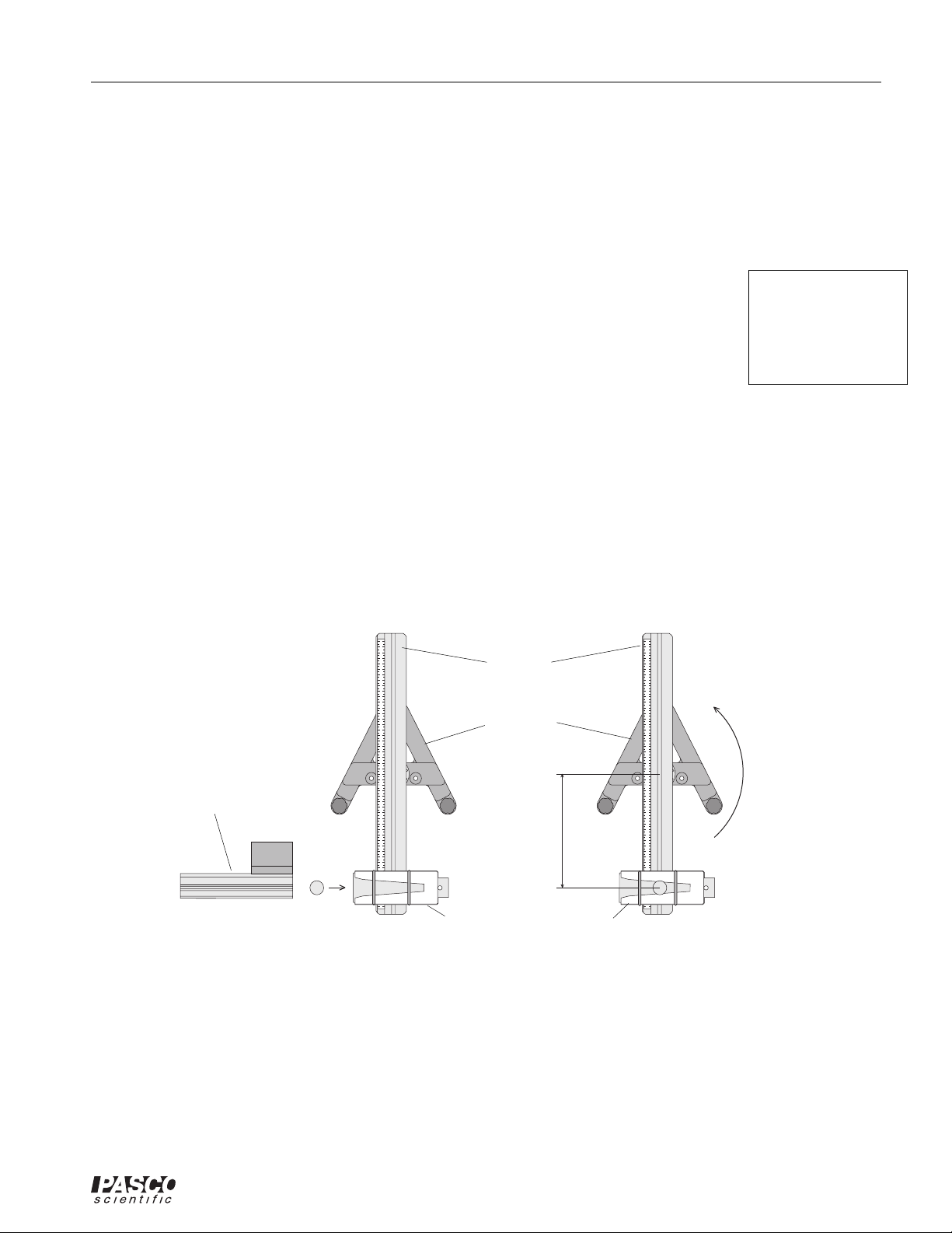
Part I: Determining the initial velocity of the ball
Setup
Projectile
Launcher
1. Clamp the Projectile Launcher to a sturdy table near one end of the table.
90
8
2. Adjust the angle of the Projectile Launcher to zero degrees so the ball will be shot off
horizontally. See Figure 1.3.
WEAR
SAFETY
GLASSES
WHEN IN USE.
0
7
0
6
0
5
0
4
0
3
0
2
0
10
0
ME-6800
Procedure
1. Put the ball into the Projectile Launcher and cock it to the long range position. Fire
one shot to locate where the ball hits the floor. At this position, tape a piece of white
paper to the floor. Place a piece of carbon paper (carbon-side down) on top of this
paper and tape it down. When the ball hits the floor, it will leave a mark on the white
paper.
2. Fire about ten shots.
3. Measure the vertical distance from the bottom of the ball as it leaves the barrel (this position is
marked on the side of the barrel) to the floor. Record
this distance in Table 1.1.
Table 1.1 Determining the Initial Velocity
4. Use a plumb bob to find the point on the
floor that is directly beneath the release
point on the barrel. Measure the horizontal
distance along the floor from the release
Horizontal distance to edge of paper =
Vertical distance =
Initial velocity =
point to the leading edge of the paper.
Record in Table 1.1.
5. Measure from the leading edge of the paper
Trial Number
1
to each of the ten dots and record these distances in Table 1.1.
6. Find the average of the ten distances and
record in Table 1.1.
7. Using the vertical distance and the average
2
3
4
5
horizontal distance, calculate the time of
flight and the initial velocity of the ball.
Record in Table 1.1 and Table 1.4.
6
7
clamp
Figure 1.3 Projectile
Launcher Setup
Distance
LONG
MEDIUM
RANGE
RANGE
CAUTION!
CAUTION!
DO NOT LOOK
DO NOT LOOK
DO NOT LOOK
DOWN BARREL!
DOWN BARREL!
DOWN THE BARREL.
PROJECTILE LAUNCHER
CAUTION!
SHORT
RANGE
SHORT RANGE
Yellow Band in Window
Indicates Range.
Launch
Use 25 mm
Position
of Ball
balls ONLY!
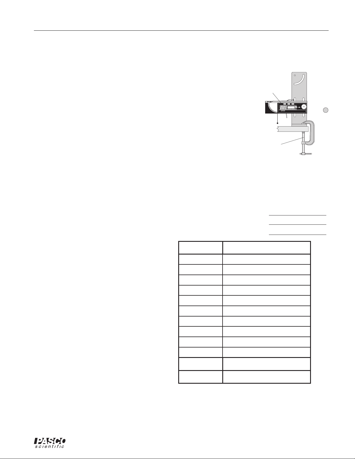
Alternate Method: Determining the Muzzle
Velocity with Photogates
1. Attach the photogate bracket to the
8
9
10
Launcher and attach two Photogates to the
bracket. Plug the Photogates into a computer or other timer.
Average
Total Distance
2. Put the ball into the Projectile Launcher and
cock it to the long range position.
3. Run the DataStudio program. Set it to measure the time between the ball blocking the two Photogates as it comes out of the Launcher.
4. Shoot the ball three times and take the average of these times. Record in Table 1.2.
11
Page 16

Complete Rotational System 012-05293F
Trial Number
Time
1
2
3
Average Time
Initial Velocity
Table 1.2 Initial Speed Using Photogates
5. The distance between the Photogates is 10 cm. Calculate the initial speed and record it in Table
1.2 and Table 1.4.
Part II: Conservation of Angular Momentum
Setup
rubber band
end view of
rotating platform
side view of
rotating platform
rubber band
tab of "catcher"
against platform
Figure 1.4: Attaching the Catcher to the Track
"catcher"
1. Find the mass of the ball and record it in Table 1.3.
2. Attach the ball catcher to the track using a rubber band as shown in Figure 1.4.
3. With the Projectile Launcher mounted as it was in Part I, aim the launcher directly down the middle of the ball catcher using the sights inside the projectile launcher. Clamp the launcher to the
table.
4. Attach the Photogate Head to the base. Connect the Photogate Head to a computer and run the
DataStudio program.
5. Set up the program so that it measures and displays angular speed.
Procedure
1. Level the rotating platform.
2. Load the Launcher with the steel ball on the long range setting.
3. Make sure the rotating platform is at rest and fire the ball into the catcher.
Record the angular speed of the platform in Table
1.3. Repeat for a total of five shots.
4. Measure the distance from the axis of rotation to
the ball in the catcher and record in Table 1.3.
Distance from axis of rotation, R =
Trial Trial
Angular Speed Angular Speed
Table 1.3 Angular Speed
Mass of ball =
12
1
2
3
4
5
Avg.
Page 17

012-05293F Complete Rotational System
Part III: Determining the Rotational Inertia
Setup
1. Attach a Photogate with a pulley and mounting rod to the
base using the black rod.
2. Connect the Photogate to a PASCO interface and connect
the interface to a computer.
3. Wind a thread around the middle step pulley on the center
shaft and pass the thread over the pulley.
Procedure
Accounting For Friction
Because the theory used to find the rotational inertia experimentally does not include friction, it will be compensated for in this experiment by finding out how
much mass over the pulley it takes to overcome kinetic friction and allow the mass to drop at a constant
speed. Then this “friction mass” will be subtracted from the mass used to accelerate the apparatus.
1. Start the DataStudio program. Select ’Smart Pulley (Linear)’ and set up a Digits display to show
velocity with three significant figures.
2. Hang a small amount of mass such as a few paper clips on the end of the thread that is over the
pulley.
3. Start monitoring data, and then give the Rotating Platform a tap to get it started moving.
4. Watch the Digits display to see the velocity.
5. If the velocity increases or decreases as the Rotating Platform turns, stop monitoring data, stop
the Rotating Platform, and adjust the amount of mass on the thread by adding or removing a paper
clip.
6. Repeat the process until the velocity stays constant.
7. Measure the mass on the end of the thread and record it as the ’Friction Mass’ in Table 1.4.
Projectile
Catcher
step pulley
Photogate
with pulley
Finding the Acceleration of the Apparatus
To find the acceleration, put about 30 g - record the exact hanging mass in Table 1.4 - over the pulley.
In the DataStudio program, set up a Graph display of Velocity versus Time.
1. Wind the thread up and hold the Rotating Platform.
2. Let the Rotating Platform begin to turn and at the same time, start recording data.
3. Let the mass descend toward the floor but STOP recording data just before the mass hits the floor.
4. Examine your Graph display of Velocity versus Time. The slope of the best fit line for your data
is the acceleration of the apparatus.
5. Record the slope in Table 1.4.
Table 1.4 Rotational Inertia Data
Friction Mass
Hanging Mass
Slope
Radius
13
Page 18

Complete Rotational System 012-05293F
Measure the Radius
1. Using calipers, measure the diameter of the step pulley about which the thread is wrapped and
calculate the radius.
2. Record the radius in Table 1.4.
Analysis
1. Calculate the average of the angular speeds in Table 1.3 and record the result in Table 1.5.
2. Calculate the rotational inertia:
• Subtract the “friction mass” from the hanging mass used to accelerate the apparatus to determine
the mass, m, to be used in the equations.
• Calculate the experimental value of the rotational inertia and record it in Table 1.5.
Table 1.5 Results
Average Angular Speed
Rotational Inertia
Calculated Initial Velocity, v
0
Measured Initial Velocity
% Difference
3. Using the average angular speed, the rotational inertia, and the distance, r, calculate the muzzle
velocity of the ball and record it in Table 1.5.
4. Calculate the percent difference between the muzzle velocities found in Parts I and II. Record in
Table 1.5.
Questions
1. What percentage of the kinetic energy is lost in the collision? Use the masses and velocities to
calculate this percentage.
%Lost
KE
----------------------------------------------
before
KE
KE
–
before
after
x100 %=
14
Page 19

012-05293F Complete Rotational System
Experiment 2: Rotational Inertia of a Point Mass
EQUIPMENT NEEDED
- DataStudio Software
- PASCO Interface (see Note) - Mass and Hanger Set
- Paper clips (for masses < 1 g) - Photogate/Pulley System
- Balance - Calipers
Purpose
The purpose of this experiment is to find the rotational inertia of a point mass experimentally and to
verify that this value corresponds to the calculated theoretical value.
Theory
Theoretically, the rotational inertia, I, of a point mass is given by I = MR2, where M is the mass, R is
the distance the mass is from the axis of rotation.
To find the rotational inertia experimentally, a known torque is applied to the object and the resulting
angular acceleration is measured. Since τ = Iα,
τ
---
I
=
α
where α is the angular acceleration which is equal to a/r and τ is the torque caused by the weight hanging
from the thread which is wrapped around the step pulley below the rotating platform, and
τ rT=
Note: If you are
using a PASPORT
interface, you will
also need a Digital
Adapter (PS-2159)
where r is the radius of the step pulley about which the thread is wound and T is the tension in the thread
when the apparatus is rotating.
Applying Newton’s Second Law for the hanging mass, m, gives (see Figure 2.1).
ΣFmgT– ma==
T
rotating
platform
"A" base
hanging
mass
Figure 2.1: Rotational Apparatus and Free-Body Diagram
a
mg
Solving for the tension in the thread gives:
Tmga–()=
15
Page 20

Complete Rotational System 012-05293F
Once the linear acceleration of the mass (m) is determined, the torque and the angular acceleration can
be obtained for the calculation of the rotational inertia.
Setup
1. Level the rotating platform.
2. Attach the square mass (point mass) to the track on the rotating platform at any radius you wish.
3. Mount the Photogate/Pulley system to the base and connect the photogate through an interface to
a computer. See Figure 2.2.
4. Attach a thread to the middle step of the step pulley and hang the thread over the 10-spoke pulley.
Allow the string to reach to the floor.
300g mass
rotating
platform
"A" base
10-spoke pulley with
photogate head
Figure 2.2: Rotational inertia of a point mass
Procedure
Part I: Measurements For the Theoretical Rotational Inertia
1. Weigh the square mass to find the mass M and
record in Table 2.1. Why is it possible to assume
that the square mass acts the same as a point mass?
2. Measure the distance from the axis of rotation to the
center of the square mass and record this radius in
Table 2.1.
Table 2.1: Theoretical Rotational Inertia
Mass, M
Radius, R
Part II: Measurement For the Experimental Method
Accounting For Friction
Because the theory used to find the rotational inertia experimentally does not include friction, it will
be compensated for in this experiment by finding out how much mass over the pulley it takes to overcome
kinetic friction and allow the mass to drop at a constant speed. Then this “friction mass” will be subtracted
from the mass used to accelerate the ring.
1. Start the DataStudio program. Select ’Smart Pulley (Linear)’ and set up a Digits display to show
velocity with three significant figures.
2. Hang a small amount of mass - such as a few paper clips - on the end of the thread that is over the
pulley.
3. Start monitoring data, and then give the Rotating Platform a tap to get it started moving.
4. Watch the Digits display to see the velocity.
16
Page 21

012-05293F Complete Rotational System
5. If the velocity increases or decreases as the platform turns, stop monitoring data, stop the platform, and adjust the amount of mass on the thread by adding or removing a paper clip.
6. Repeat the process until the velocity stays constant as the mass falls.
7. Measure the mass on the end of the thread and record it as the ’Friction Mass’ in Table 2.2.
Finding the Acceleration of the Point Mass and Apparatus
To find the acceleration, put about 50 g - measure the exact mass and record it in Table 2.2 - on the
end of the thread over the pulley. In DataStudio, set up a Graph display of Velocity versus Time.
1. Wind the thread up and hold the Rotating Platform.
2. Let the platform begin to turn and at the same time, start recording data.
3. Let the mass fall toward the floor but STOP recording data just before the mass hits the floor.
4. Examine your Graph display of Velocity versus Time. The slope of the best ’Linear Fit’ for your
data is the acceleration of the apparatus.
5. Record the slope in Table 2.2.
Table 2.2: Rotational Inertia Data
Point Mass and Apparatus Apparatus Alone
Friction Mass
Hanging Mass
Slope
Radius, r
Measure the Radius
1. Using calipers, measure the diameter of the step pulley about which the thread is wrapped and
calculate the radius.
2. Record the radius in Table 2.2.
Finding the Acceleration of the Apparatus Alone
Since in Finding the Acceleration of the Point Mass and Apparatus the apparatus is rotating as well
as the point mass, it is necessary to determine the acceleration, and the rotational inertia, of the apparatus
by itself so this rotational inertia can be subtracted from the total, leaving only the rotational inertia of
the point mass.
1. Take the point mass off the rotational apparatus and repeat Finding the Acceleration of the
Point Mass and Apparatus for the apparatus alone.
NOTE: that it will take less “friction mass” to overcome the new kinetic friction and it is
only necessary to put about 20 g on the end of the thread over the pulley.
2. Record the data in Table 2.2.
Calculations
1. Subtract the “friction mass” from the hanging mass used to accelerate the apparatus to determine
the mass, m, to be used in the equations.
2. Calculate the experimental value of the rotational inertia of the point mass and apparatus together
and record in Table 2.3.
3. Calculate the experimental value of the rotational inertia of the apparatus alone. Record in
Table 2.3.
17
Page 22

Complete Rotational System 012-05293F
4. Subtract the rotational inertia of the apparatus from the combined rotational inertia of the point
mass and apparatus. This will be the rotational inertia of the point mass alone. Record in Table
2.3.
5. Calculate the theoretical value of the rotational inertia of the point mass. Record in Table 2.3.
6. Use a percent difference to compare the experimental value to the theoretical value. Record in
Table 2.3.
Table 2.3: Results
Rotational Inertia for Point Mass
and Apparatus Combined
Rotational Inertia for
Apparatus Alone
Rotational Inertia for Point Mass
(experimental value)
Rotational Inertia for Point Mass
(theoretical value)
% Difference
18
Page 23

012-05293F Complete Rotational System
Experiment 3: Centripetal Force
EQUIPMENT NEEDED
- Centripetal Force Accessory (ME-8952) - Rotating Platform (ME-8951)
- Stopwatch - Balance
- Graph paper (2 sheets) - Mass and Hanger Set
- String
Purpose
The purpose of this experiment is to study the effects of varying the mass of the object, the radius of
the circle, and the centripetal force on an object rotating in a circular path.
Theory
When an object of mass m, attached to a string of length r, is rotated in a horizontal circle, the centripetal
force on the mass is given by:
F
2
mv
---------
==
mrω
r
2
where v is the tangential velocity and ω is the angular speed (v = r ω). To measure the velocity, the
time for one rotation (the period, T) is measured. Then:
2πr
---------
v
=
T
and the centripetal force is given by:
2
4π
mr
----------------
F
=
2
T
Setup
Level the "A" base and rotating platform as described in the ME-8951 assembly section in the
introduction to this manual.
Procedure
Part I: Vary Radius (constant force and mass)
1. The centripetal force and the mass of the hanging object will be held constant for this part of the
experiment. Weigh the object and record its mass in Table 3.1. Hang the object from the side post
and connect the string from the spring to the object. The string must pass under the pulley on the
center post. See Figure 3.1.
19
Page 24

Complete Rotational System 012-05293F
clamp-on
pulley
hanging
mass
side post
assembly
Figure 3.1: Centripetal Force Apparatus
string
center post
assembly
rotating
platform
"A" base
2. Attach the clamp-on pulley to the end of the track nearer to the hanging object. Attach a string to
the hanging object and hang a known mass over the clamp-on pulley. Record this mass in Table
3.1. This establishes the constant centripetal force.
3. Select a radius by aligning the line on the side post with any desired position on the measuring
tape. While pressing down on the side post to assure that it is vertical, tighten the thumb screw on
the side post to secure its position. Record this radius in Table 3.1.
4. The object on the side bracket must hang vertically: On the center post, adjust the spring bracket
vertically until the string from which the object hangs on the side post is aligned with the vertical
line on the side post.
5. Align the indicator bracket on the center post with the orange indicator.
6. Remove the mass that is hanging over the pulley and remove the pulley.
7. Rotate the apparatus by hand, increasing the speed until the orange indicator is centered in the
indicator bracket on the center post. This indicates that the string supporting the hanging object is
once again vertical and thus the hanging object is at
the desired radius.
Table 3.1: Varying the Radius
8. Maintaining this speed, use a stopwatch to time
ten revolutions. Divide the time by ten and
record the period in Table 3.1.
9. Move the side post to a new radius and repeat
Mass hanging over the pulley =
Mass of the object =
Slope from graph =
the procedure. Do this for a total of five radii.
Radius Period (T) T
Analysis
1. The weight of the mass hanging over the pulley
is equal to the centripetal force applied by the
spring. Calculate this force by multiplying the
mass hung over the pulley by “g” and record this
force at the top of Table 3.2.
2. Calculate the square of the period for each trial
and record this in Table 3.1.
3. Plot the radius versus the square of the period. This will give a straight line since:
F
-------------
⎛⎞
r
=
4π2m
⎝⎠
2
T
2
4. Draw the best-fit line through the data points and measure the slope of the line. Record the slope
in Table 3.1.
20
Page 25

012-05293F Complete Rotational System
5. Calculate the centripetal force from the slope
Table 3.2: Results (varying raduis)
and record in Table 3.2.
6. Calculate the percent difference between the
two values found for the centripetal force
Centripetal Force = mg
Centripetal Force From Slope
and record in Table 3.2.
Percent Difference
Part II: Vary Force (constant radius and mass)
The radius of rotation and the mass of the hanging object will be held constant for this part of the
experiment.
1. Weigh the object and record its mass in Table 3.3. Hang the object from the side post and connect
the string from the spring to the object. The string must pass under the pulley on the center post.
2. Attach the clamp-on pulley to the end of the track nearer to the hanging object. Attach a string to
the hanging object and hang a known mass over the clamp-on pulley. Record this mass in Table
3.3. This determines the centripetal force.
3. Select a radius by aligning the line on the side post with any desired position on the measuring
tape. While pressing down on the side post to assure that it is vertical, tighten the thumb screw on
the side post to secure its position. Record this radius in Table 3.3.
4. The object on the side bracket must hang vertically: On the center post, adjust the spring bracket
vertically until the string from which the object hangs on the side post is aligned with the vertical
line on the side post.
5. Align the indicator bracket on the center post with the orange indicator.
6. Remove the mass that is hanging over the pulley and remove the pulley.
7. Rotate the apparatus, increasing the speed until the orange indicator is centered in the indicator
bracket on the center post. This indicates that the string supporting the hanging object is once
again vertical and thus the hanging object is at the desired radius.
8. Maintaining this speed, use a stopwatch to time ten revolutions. Divide the time by ten and record
the period in Table 3.3.
9. To vary the centripetal force, clamp the pulley to the track again and hang a different mass over
the pulley. Keep the radius constant and repeat the procedure from Step #4. Do this for a total of
five different forces.
Analysis
1. The weight of the mass hanging over the pulley is equal to the centripetal force applied by the
spring. Calculate this force for each trial by multiplying the mass hung over the pulley by “g” and
record the results in Table 3.3.
2. Calculate the inverse of the square of the period for each trial and record this in Table 3.3.
3. Plot the centripetal force versus the inverse square of the period. This will give a straight line
since:
2
mr
4π
----------------
=
F
2
T
4. Draw the best-fit line through the data points and measure the slope of the line. Record the slope
in Table 3.3.
21
Page 26

Complete Rotational System 012-05293F
Table 3.3: Varying the Centripetal Force
Mass of the object =
Radius =
Slope from graph =
Mass Over Pulley
Centripetal Force = mg Period (T)
5. Calculate the mass of the object from the slope and record in Table 3.4.
6. Calculate the percent difference
between the two values found for
Table 3.4: Results (varying the centripetal force)
the mass of the object and record
in Table 3.4.
Mass of Object (from scale)
Mass of Object (from slope)
Percent Difference
Part III: Vary Mass (constant radius and force)
1
2
T
The centripetal force and the radius of rotation will be held constant for this part of the experiment.
1. Weigh the object with the additional side masses in place. Record its mass in Table 3.5. Hang the
object from the side post and connect the string from the spring to the object. The string must pass
under the pulley on the center post.
2. Attach the clamp-on pulley to the end of the track nearer to the hanging object. Attach a string to
the hanging object and hang a known mass over the clamp-on pulley. Record this mass in Table
3.5. This establishes the constant centripetal force.
3. Select a radius by aligning the line on the side post with any desired position on the measuring
tape. While pressing down on the side post to assure that it is vertical, tighten the thumb screw on
the side post to secure its position. Record this radius in Table 3.5.
4. The object on the side bracket must hang vertically: On the center post, adjust the spring bracket
vertically until the string from which the object hangs on the side post is aligned with the vertical
line on the side post.
5. Align the indicator bracket on the center post with the orange indicator.
6. Remove the mass that is hanging over the pulley and remove the pulley.
7. Rotate the apparatus, increasing the speed until the orange indicator is centered in the indicator
bracket on the center post. This indicates that the string supporting the hanging object is once
again vertical and thus the hanging object is at the desired radius.
8. Maintaining this speed, use a stopwatch to time ten revolutions. Divide the time by ten and record
the period in Table 3.5.
9. Vary the mass of the object by removing the side masses. Keep the radius constant and measure
the new period. Weigh the object again and record the mass and period in Table 3.5.
22
Page 27

012-05293F Complete Rotational System
Table 3.5: Varying the Mass of the Object
Mass hanging over pulley =
Centripetal Force = mg =
Radius =
Mass of Object % Difference
Period (T)
Calculated
Centripetal Force
Analysis
1. The weight of the mass hanging over the pulley is equal to the centripetal force applied by the
spring. Calculate this force by multiplying the mass hung over the pulley by “g” and record the
result at the top of Table 3.5.
2. Calculate the centripetal force for each trial using:
2
mr
4π
----------------
=
F
2
T
and record this in Table 3.5.
3. Calculate the percent difference between the calculated centripetal force for each trial and mg.
Record in Table 3.5.
Questions
1. When the radius is increased, does the period of rotation increase or decrease?
2. When the radius and the mass of the rotating object are held constant, does increasing the period
increase or decrease the centripetal force?
3. As the mass of the object is increased, does the centripetal force increase or decrease?
23
Page 28

Complete Rotational System 012-05293F
Notes:
24
Page 29

012-05293F Complete Rotational System
LI
f
==
I
i
I
---
rT=
FmgT– ma==
Tmga–
=
Experiment 4: Conservation of Angular Momentum
Using a Point Mass
EQUIPMENT REQUIRED
- DataStudio Program - Rotating Platform (ME-8951)
- PASCO Interface (see Note) - Photogate/Pulley System
- Rotational Inertia Accessory (ME-8953) - Balance
Purpose
A mass rotating in a circle is pulled in to a smaller radius and the new angular speed is predicted
using conservation of angular momentum.
Theory
Angular momentum is conserved when the radius of the circle is changed
Note: If you are
using a PASPORT
interface, you will
also need a Digital
Adapter (PS-2159)
.
ω
where I
iωiIf
is the initial rotational inertia and ωi is the initial angular speed. So the final rotational
i
speed is given by:
i
-- -
ω
=
ω
f
I
f
To find the rotational inertia experimentally, a known torque is applied to the object and the
resulting angular acceleration is measured. Since τ = Iα,
τ
=
α
where α is the angular acceleration which is equal to a/r and τ is the torque caused by the
weight hanging from the thread which is wrapped around the base of the apparatus.
τ
where r is the radius of the cylinder about which the thread is wound and T is the tension in
the thread when the apparatus is rotating.
Applying Newton’s Second Law for the hanging mass, m, gives (See Figure 4.1)
Σ
Solving for the tension in the thread gives:
()
Once the linear acceleration of the mass (m) is determined, the torque and the angular
acceleration can be obtained for the calculation of the rotational inertia.
25
Page 30

Complete Rotational System 012-05293F
T
rotating
platform
"A" base
mg
hanging
mass
a
Figure 4.1: Rotational Apparatus and Free-Body Diagram
Part I: Conservation of Angular Momentum
Setup
1. Level the apparatus using the square on the track as shown in the leveling instructions in the
Assembly Section.
2. Slide a thumb screw and square nut into the T-slot on the top of the track and tighten it down at
about the 5 cm mark. This will act as a stop for the sliding square mass. See Figure 4.2.
string
300g mass
center post
rotating
stop screws (2)
"A" base
platform
Figure 4.2: Set-up for conservation of angular momentum
3. With the side of the square mass that has the hole oriented toward the center post, slide the square
mass onto the trac k by ins er ti ng i ts square nut into the T-slot, bu t d o not tighten the thumb screw;
the square mass should be free to slide in the T-slot.
4. Slide a second thumb screw and square nut into the T-slot and tighten it down at about the 20 cm
mark. Now the square mass is free to slide between the two limiting stops.
5. Move the pulley on the center post to its lower position. Remove the spring bracket from the center post and set it aside.
6. Attach a string to the hole in the square mass and thread it around the pulley on the center post
and pass it through the indicator bracket.
7. Mount the Photogate on the rod on the base and position it so it straddles the holes in the pulley
on the center rotating shaft.
8. Start the DataStudio program. Connect the Photogate to a PASCO int er fa ce a nd c onnect the interface to a computer (if needed).
26
Page 31

012-05293F Complete Rotational System
Procedure
1. Select ’Smart Pulley (Rotationa l)’ as t he t ype of sen sor. Set up a Graph disp lay o f Velocity (rad/s)
versus time.
2. Hold the string just above the center post. With the square mass against the outer stop, give the
track a spin using your hand.
3. Click ’Start’ to begin recording data. After about 20 data points have been taken, pull up on the
string to cause the square mass to slide from the outer stop to the inner stop.
4. Continue to hold the string up and take about 20 data points after pulling up on the string. Click
’Stop’ to end recording dat a.
5. Examine the Graph display of Velocity (rad/s) versus time.
The graph shows the angular speed before and after the
square mass is pulled toward the inner stop. Rescale the
graph if necessary.
6. Use the Smart Cursor tool to determine the angular speed
immediately before and immediately after pulling the
string. Record these values in Table 4.1.
7. Repeat the experiment a total of thr ee times with diffe rent
initial angular speeds . Record these values in Table 4.1.
Trial Number
1
2
3
Table 4.1: Data
Angular Speeds
Initial Final
Part II: Determining the Rotational Inertia
Measure the rotational inertia of th e apparatus twice: once with the squ are mass in its initial
position and once with it in its final position.
Setup
1. Attach a Photogate with Pulley to a mounting rod and attach the mounting rod to the black support rod on the base.
2. Wind a thread aro und the pulley on the cen ter shaft and pass the thread over the Pulley. See Figure 4.3.
string
300g mass
stop screws (2)
center post
rotating
platform
10-spoke pulley with
photogate head
"A" base
Figure 4.3: Set-up for determining rotational inertia
27
hanging mass
Page 32

Complete Rotational System 012-05293F
Procedure
Accounting For Friction
Because the theory used to find the rotational inertia experimentally does not include friction, it will
be compensated for in this exp er iment by fi ndi ng out how much mass over the pulley it takes to overcome kinetic fricti on an d allo w the mass t o dr op at a consta nt spee d. Then th is “fricti on mass” wil l be
subtracted from the mass used to accelerate the apparatus.
1. Start the DataStudio program. Select ’Smart Pulley (L inear)’ and set up a Digits display to how
velocity with three significant figures.
2. Hang a small amount of mass (such as a few paper clips) on the end of the thread that is over the
pulley. Make sure that the thread is wound around the step pulley.
3. Start monitoring data, and then give the Rotating Platform a tap to get it started moving.
4. Watch the Digits display to see the velocity.
5. If the velocity increases or decreases as the platform turns, stop monitoring data, stop the platform, and adjust the amount of mass on the end of the thread.
6. Repeat the process until the velocity stays constant.
7. Measure the mass on the end of the thread and record it as ’Friction Mass’ in Table 4.2..
Finding the Acceleration of the Apparatus
T o fi nd the accele rati on, put about 30 g - recor d the exac t hang ing mass in Table 4.2 - over the pulley.
In the DataStudio program, set up a Graph display of Velocity versus Time.
1. Wind the thread up and hold the Rotating Platform.
2. Let the Rotating Platform begin to turn and at the same time, START recording d ata.
3. Let the mass descend toward the floor but STOP re cordi ng data ju st befor e the mass hits the floor.
4. Examine your graph of velocity versus time. The slope ("m") of the best fit line for your data is
the acceleration (use F it>Linear Fit). Record the slope in Table 4.2.
Repeat the procedure for the mass at the inner stop. Record results in Table 4.2.
Measure Radius
1. Using calipers, measure the diameter of the step pulley about which the thread is wrapped and
calculate the radius.
2. Record the radius in Table 4.2.
Table 4.2 Rotational Inertia Data
Mass at Outer Stop Mass at Inner Stop
Friction Mass
Hanging Mass
Slope
Radius
Rotational Inertia
28
Page 33

012-05293F Complete Rotational System
K
1
i
K
1
f
Analysis
1. Calculate the rotational inertias:
• Subtract the “friction mass” from the hanging mass used to accelerate the apparatus to
determine the mass, m, to be used in the equations.
• Calculate the experimental values of the rotational inertia and record it in Table 4.3.
2. Calculate the expected (theoretical) values for the final angular velocity and record these values
in Table 4.3.
Table 4.3: Results
Trial #1 Trial #2
Trial #3
Theoretical Angular Speed
% Difference
3. For each trial, calculate the percent difference between the experimental and the theoretical values of the final angular velocity and record these in Table 4.3.
Questions
Calculate the rotational kinetic energy before the string was pulled.
-- -
E
Then calculate the rotational kinetic energy after the string was pulled.
E
1. Which kinetic energy is greater?
2. Why?
ω
=
I
i
i
2
-- -
ω
=
I
f
f
2
29
Page 34

Complete Rotational System 012-05293F
Notes:
30
Page 35

012-05293F Complete Rotational System
I
1
I
1
2
I
1
2
I
---
Experiment 5: Rotational Inertia of Disk and Ring
EQUIPMENT REQUIRED
- DataStudio Program - Mass and Hanger Set
- PASCO Interface (see Note) - Paper Clips (for masses < 1 g)
- Rotational Inertia Accessory (ME-8953) - Balance
- Photogate/Pulley System - Calipers
Purpose
The purpose of t his experiment is to fin d the rotational inertia of a ring and a disk expe rimentally
and to verify that these values correspond to the calculated theoretical values.
Theory
Theoretically, the rotati onal inerti a, I, of a rin g about its center o f mass is given
by:
-- -
MR
2
2
2
R
+()=
1
2
Note: If you are
using a PASPORT
interface, you will
also need a Digital
Adapter (PS-2159)
R
R
1
2
where M is the mass of the ring, R
is the inner radius of the r in g, and R2 is the
1
outer radius of the ring. See Figure 5.1.
The rotational inertia of a disk about its center of mass is given by:
Figure 5.1: Ring
-- -
=
MR
2
where M is the mass of the disk and R is the radius of the disk. The rotati onal ine rtia of a disk
about its diameter is given by:
-- -
=
MR
4
R
R
Disk about center of Mass Disk about Diameter
Figure 5.2:
To find the rotational inertia experimentally, a known torque is applied to the object and the
resulting angular acceleration is measured. Since τ = Iα,
τ
=
α
31
Page 36

Complete Rotational System 012-05293F
rT=
FmgT– ma==
Tmga–
=
where α is the angular acceleration which is equal to a/r and τ is the torque caused by the
weight hanging from the thread which is wrapped around the base of the apparatus.
τ
where r is the radius of the cylinder about which the thread is wound and T is the tensi on in
the thread when the apparatus is rotating.
Applying Newton’s Second Law for the hanging mass, m, gives (See Figure 5.3)
Σ
rotational disk
"A" base
Figure 5.3: Rotational Apparatus and Free-Body Diagram
Solving for the tension in the thread gives:
()
Once the linear acceleration of the mass (m) is determined, the torque and the angular
acceleration can be obtained for the calculation of the rotational inertia.
Setup
1. Remove the track from the Rotating Platform and place the
disk directly on t he cent er sh aft a s shown i n Figur e 5.4. Th e
side of the disk that has the indentation for the ring should
be up.
2. Place the ring on the disk, seating it in this indentation.
3. Mount the Photogate/Pulley System to the base and connect
it to a PASCO interface.
4. Attach a thread to the top step of the three- step pulley on the
Rotational Apparatus shaft and suspend the string over the
pulley of the Photogate/ Pulle y System. At tach a ha nger and
mass to the en d of the thread.
5. Start the DataStudio program.
T
a
hanging
mass
mass ring
rotational
disk
"A" base
mg
10-spoke pulley with
photogate head
Figure 5.4: Set-up for Disk and Ring
mass and
hanger
Procedure
Measurements for the Theoretical Rotational Inertia
1. Weigh the ring and disk to find their masses and record these masses in Table 5.1.
2. Measure the inside and outside diameters of the ring and calculate the radii R
Table 5.1.
3. Measure the diameter of the disk and calculate the radius R and record it in Table 5.1.
32
and R2. Record in
1
Page 37

012-05293F Complete Rotational System
Table 5.1: Theoretical Rotational Inertia
Mass of Ring
Mass of Disk
Inner Radius of Ring
Outer Radius of Ring
Radius of Disk
Measurements for the Experimental Method
Accounting For Friction
Because the theory used to find the rotational inertia experimentally does not include friction, it will
be compensated for in this ex periment by finding out how much mass over the pulley it takes to overcome
kinetic frictio n and allow the mass to drop at a cons tant speed. Then this “frictio n mass” will be subtracted
from the mass used to accelerate the apparatus.
1. In the DataStudio program, select ’Smart Pulley (Linear)’ and set up a Digits display to show
velocity with three significant figures.
2. Hang a small amount of mass such as a few paper clips on the end of the thread that is over the
pulley.
3. Start monitoring data, and then give the Rotational Disk a tap to get it started moving.
4. Watch the Digits display to see the velocity.
5. If the velocity increases or decreases as the Rotational Disk turns, stop monitoring data, stop the
Rotational Disk, and adjust the amount of mass on the thread by adding or removing a paper clip.
6. Repeat the process until the velocity stays constant.
7. Measure the mass on the end of the thread and record it as the ’Friction Mass’ in Table 5.2.
Table 5.2: Rotational Inertia Data
Ring and Disk
Combined
Disk Alone
Disk Vertical
Friction Mass
Hanging Mass
Slope
Radius
Finding the Acceleration of Ring and Disk
To find the acc elerati on, put about 50 g - r ecord the exact hangi ng ma ss i n Table 5.2 - o ver t he pul ley.
In the DataStudio program, set up a Graph display of Velocity versus Time.
1. Wind the thread up and hold the Rotati ng Platform.
2. Let the Rotating Platform begin to turn and at the same time, start recording data.
3. Let the mass descend toward the floor but STOP re cordi ng data ju st befo re the mass hits the floor.
4. Examine your Graph display of Velocity versus Time. The slope of the best fit line for your data
is the acceleration of the apparatus.
5. Record the slope in Table 5.2.
33
Page 38

Complete Rotational System 012-05293F
Measure t he Radius
1. Using calipers, measure the diameter of the cyl inder about which t he th read i s wrapp ed and cal culate the rad ius. Record i n Table 5.2.
Finding the Acceleration of the Disk Alone
Since in Finding the Acceleration of Ring and Disk the disk is rotating as well as the ring,
it is necessary to determine the acceleration, and the rotational inertia, of the disk by itself so
this rotational in ertia can be subtract ed from the total, le aving only the rota tional inert ia of the
ring.
1. To do this, take the r ing off the rotationa l app aratu s a nd re peat Findi ng the Accelera tion of Ring
and Disk for the disk alone.
NOTE: that it will take less “f riction mass” to overcome the new kinetic friction and i t is
only necessary to put about 30 g over the pulley in Finding the Acceleration of the Disk
Alone.
Disk Rotating on an Axis Through Its Diameter
Remove the disk from the shaft and rot ate it up on its side. Mount the disk vertically by inse rting
the shaft in one of the two “D”-shaped holes on the edge of the disk. See Figure 5.5.
WARNING! Never mount the disk vertically using the adapter on the track. The adapter is
too short for this purpose and the disk might fall over while being rotated.
Repeat steps Measure the Radius and Finding the Acceleration of the Disk Alone to
determine the rotational inertia of the disk about its diameter. Record the data in Table 5.2.
rotational disk
"D" hole of
rotational disk
rotating shaft
"A" base
Figure 5.5: Disk mounted vertically
Calculations
Record the results of the following calculations in Table 5. 3.
1. Subtract the “friction mass” from the hanging mass used to acc el er ate the apparatus to determine
the mass, m, to be used in the equations.
2. Calculate the experimental value of the rotational inertia of the ring and disk together.
3. Calculate the experimental value of the rotational inertia of the disk alone.
4. Subtract the rotational inertia of the disk from the total rotational inertia of the ring and disk.
This will be the rotational inertia of the ring alone.
5. Calculate the experimental value of the rotational inertia of the disk about its diameter.
6. Calculat e the theoretical value of the rotational inerti a of the ring.
34
Page 39

012-05293F Complete Rotational System
7. Calculate the theoretical value of the rotational inertia of the disk about its center of mass and
about its diameter.
8. Use a percent difference to compare the experimental values to the theoretical values.
Table 5.3: Results
Rotational Inertia for Ring and
Disk Combined
Rotational Inertia for Disk Alone
(experimental value)
Rotational Inertia for Ring
(experimental value)
Rotational Inertia for Vertical Disk
(experimental value)
Rotational Inertia for Disk
(theoretical value)
Rotational Inertia for Ring
(theoretical value)
Rotational Inertia for Vertical Disk
(theoretical value)
% Difference for Disk
% Difference for Ring
% Difference for Vertical Disk
35
Page 40

Complete Rotational System 012-05293F
Notes:
36
Page 41

012-05293F Complete Rotational System
I
1
2
I
I
2
I
--rT=
Experiment 6: Rotational Inertia of Disk Off-Axis
(Fixed/Rotating)
EQUIPMENT REQUIRED
- DataStudio Program - Calipers
- PASCO Interface (See Note) - Mass and Hanger Set
- Rotational Inertia Accessory (ME-8953) - Paper Clips (for masses < 1 g)
- Photogate/Pulley System - Balance
Purpose
The purpose of this exper ime nt i s to f ind the r otational inertia of a disk about an axi s parallel
to the center of mass axis.
Theory
Theoretically, the rota tional inertia, I, of a disk about a perpendicular axis through its center
of mass is given by:
cm
-- -
=
MR
2
Note: If you a re
using a PASPORT
interface, y ou will
also need a Digital
Adapter (PS-2159)
where M is the mass of the disk and R is the radius of the di sk. The rot ation al iner tia of a disk
about an axis parallel to the center of mass axis is given by:
IcmMd2+=
where d is the distance between the two axes.
In one part of this experiment, the disk is mounted on its ball bearing side which allows the
disk to free ly rotate relative to the track. So as the track is rotated, the di sk does not rotate
relative to its center of mass . Since th e disk is not rota ting a bout i ts ce nter o f mass, it act s as a
point mass rather than an extende d object and its rotational inerti a reduces fr om:
IcmMd2 to I+ Md
==
To find the rotational inertia experimentally, a known torque is applied to the object and the
resulting angular acceleration is measured. Since τ = Iα;
τ
=
α
where α is the angular acceleration which is equal to a/r and τ is the torque caused by the
weight hanging f rom the thread which is wrapped ar oun d t he three step pulley on the shaft of
the apparatus.
τ
where r is the radius of the st ep pulley ab out which the thread is wound and T is the tension in
the thread when the apparatus is rotating.
37
Page 42

Complete Rotational System 012-05293F
FmgT– ma==
Tmga–
=
Applying Newton’s Second Law for the hanging mass, m, gives (See Figure 6.1)
Σ
rotating plat-
form
rotational disk
platform
adapter
"A" base
hanging
mass
T
a
mg
Figure 6.1: Rotational Apparatus and Free-Body Diagram
Solving for the tension in the thread gives:
()
Once the linear acceleration of the mass (m) is determined, the torque and the angular
acceleration can be obtained for the calculation of the rotational inertia.
Setup
1. Set up the Rotational Accessory as shown in Figure 6.2. Mount the disk with its bearing side up.
Use the platform adapter to fasten the disk to the track at a large radius.
2. Mount two square masses on the opposite end of the platform to act as a counterweight. Be sure
to tighten the screws.
3. Mount the Photogate/Pulley System to the base and connect it to an interface.
4. Run the DataStudio program.
rotational disk
platform
adapter
"A" base
Figure 6.2: Set-up for Disk Off-Axis
rotating
platform
10-spoke pulley with
photogate head
hanging
mass
Measurements For the Theoretical Rotational Inertia
Record these measurements in Table 6.1.
1. Weigh the disk to find the mass M.
2. Measure the diameter and calculate the radius R.
3. Measure the distance, d, from the axis of rotation to the center of the disk.
38
Page 43

012-05293F Complete Rotational System
Table 6.1: Theoretical Rotational Inertia
Mass of Disk
Radius of Disk
Distance Between
Parallel Axis
Measurements For the Experimental Method
Accounting For Friction
Because the theory used to find the rotational inertia experimentally does not include friction, it will
be compensated for in this ex periment by finding out how much mass over the pulley it take s to overcome
kinetic friction and allow the mass to drop at a constant speed. Then this “friction mass” will be subtracted
from the mass used to accelerate the apparatus.
1. In the DataStudio program, select ’Smart Pulley (Linear)’ and set up a Digits display to show
velocity with three significant figures.
2. Hang a small amount of mass such as a few paper clips on the end of the thread that is over the
pulley.
3. Start monitoring data, and then give the Rotational Disk a tap to get it started moving.
4. Watch the Digits display to see the velocity.
5. If the velocity increases or decreases as the Rotational Disk turns, stop monitoring data, stop the
Rotational Disk, and adjust the amount of mass on the thread by adding or removing a paper clip.
6. Repeat the process until the velocity stays constant.
7. Measure the mass on the end of the thread and record it as the ’Friction Mass’ in Table 6.2.
Finding the Acceleration of Disk and Track
Table 6.2: Rotational Inertia Data
Fixed Disk and
Track Combined
Track Alone
Rotating Disk and
Track Combined
Friction Mass
Hanging Mass
Slope
Radius
To find the acceleration , put about 50 g - rec ord the exact hanging mass in Tabl e 5.2 - over the pull ey.
In the DataStudio program, set up a Graph display of Velocity versus Time.
1. Wind the thread up and hold the Rotati ng Platform.
2. Let the Rotating Platform begin to turn and at the same time, start recording data.
3. Let the mass descend toward the floor but STOP reco rdi ng data j ust bef ore the mas s hits t he floor.
4. Examine your Graph display of Velocity versus Time. The slope of the best fit line for your data
is the acceleration of the apparatus.
5. Record the slope in Table 6.2.
39
Page 44

Complete Rotational System 012-05293F
Measure t he Radius
1. Using calipers, measure the diameter of the c ylind er about which t he thr ead is wrappe d a nd cal culate the rad ius. Record i n Table 6.2.
Finding the Acceleration of Track Alone
Since in Finding the Acc eleration of Dis k and Track the track is rotating as well as the disk,
it is necessary to determine the acceleration, and the rotational inertia, of the track by itself so
this rotational inertia can be subtracted from the total, leaving only the rotational inertia of the
disk.
1. To do this, ta ke the dis k of f t he rot atio nal appara tus a nd repe at Findi ng the Acceleration of Disk
and Track for the track alone.
NOTE: It will take less “friction mass” to overcome the new kinetic friction and it is only
necessary to put about 30 g over the pulley in Finding the Acceleration of Track Alone.
Disk Using Ball Bearings (Free Disk)
Mount the disk upside- down at the same radius as before. Now the ball bearings a t the center
of the disk will allow t he disk t o rota te relativ e to the tr ack. Repea t Account ing For Friction
and Finding the Acceleration of Disk and Track for this case and record the data in Table 6.2.
Calculations
Record the results of the following calculations in Table 6.3.
1. Subtract the “friction mass” from the hanging mass used to accelerate the apparatus to determine
the mass, m, to be used in the equations.
2. Calculate the experimental value of the rotational inertia of the fixed disk and track combined.
3. Calculate the experimental value of the rotational inertia of the track alone.
4. Subtract the rotational inertia of the track f rom the rotational inertia of the fixed disk and track.
This will be the rotational inertia of the fixed disk alone.
5. Calculate the experimental value
of the rotat ional inerti a of the
fixed disk and track combined.
6. Subtract the rotational inertia of the track from the
rotational inertia of the free
disk and track. This will be
the rotational inertia of the
free disk alone.
7. Calculate the theoretical
value of the rotational inertia of the fixed disk off
axis.
8. Calculate the theoretical
value of a point mass having the mass of the disk.
9. Use a percent difference to
compare the experimental
values to the theoretical
values.
Rotational Inertia for Fixed Disk
and Track Combined
Rotational Inertia for Track Alone
Rotational Inertia for Fixed Disk
Off-Axis (experimental value)
Rotational Inertia for Free Disk
and Track Combined
Rotational Inertia for Free Disk
Alone (experimental value)
Rotational Inertia for Fixed Disk
Off-Axis (theoretical value)
Rotational Inertia for Point Mass
(theoretical value)
% Difference for Fixed
% Difference for Free Disk
Table 6.3: Results
40
Page 45

012-05293F Complete Rotational System
LI
f
==
I
1
2
I
1
1
i
Experiment 7: Conservation of Angular
Momentum
EQUIPMENT REQUIRED
- DataStudio Program - PASCO Interface
- Rotational Inertia Accessory (ME-8953) - Balance
- Rotating Platform (ME-8951) - Photogate/Pulley System
Purpose
A non-rotating ring is dropped onto a rotating disk and the final angular speed of the system
is compared with the value predicted using conservation of angular momentum.
Theory
When the ring is dropped ont o the r otati ng dis k, ther e is no n et tor que on t he syst em since the
torque on the ring is equal an d opposite to the torque on the disk. Therefore, there is no change
in angular momentum. Angular momentum is conserved
.
where I
inertia is that of a disk
and the final rotational inertia of the combined disk and ring is
Note: If you are
using a PASPORT
interface, you will
also need a Digital
Adapter (PS-2159)
iωiIf
is the initia l rot atio nal iner tia a nd ωi is the initial angular speed. The initial rotational
i
-- -
R
=
M
i
1
2
ω
2
2r1
2
r
+()+=
2
2
-- -
M
f
2
-- -
R
M
1
2
So the final rotational speed is given by
2
M1R
-------------------------------------------------
=
ω
f
M1R2M2r
ω
2
2
r
+()+
1
2
Setup
1. Level the apparatus using the square mass on the track.
2. Assemble the Rotational Inertia Accessory as shown in Figure
7.1. The side of th e disk with the indentatio n f or the ring should
be up.
3. Mount the Photogate on the metal rod on the base and posit ion it
so it straddles the holes in the pulley on the center rotating shaft.
4. Start the DataStudio program. Select ’Smart Pulley (Rotational)’ as the sensor.
5. Set up a Graph display of Velocity (rad/s) versus Time (s).
Rotational Disk
(indentation up)
"A"-base
Figure 7.1: Assembly for Dropping
Ring onto Disk
41
Page 46

Complete Rotational System 012-05293F
Procedure
1. Hold the ring just above the center of the disk. Give the disk a spin using your hand.
2. Start recording data. After about 25 data points have been taken, drop the ring onto the spinning
disk. See Figure 7.2.
3. Continue to take data after the collision for a few seconds and then stop recording data.
dropped ring
photogate head
rotational disk
"A" base
Figure 7.2: Experiment Setup
4. Examine the Graph display of the rotational speed versus time. Use the Autoscale tool to resize
the axes if necessary.
5. In the Graph display, use the Smart Tool to determine the angular velocity immed iately befo re
and immediately after the collision. Record these values in Table 7.1.
6. Weigh the disk and ring and measure the radii. Record these values in Table 7.1.
Analysis
1. Calculate the expected (theoretical) value for the final angular
velocity and record this value in
Table 7.1.
2. Calculate the percent difference
between the experimental and
the theoretical values of the final
angular velocity and record in
Table 7.1.
Table 7.1: Data and Results
Initial Angular Speed
Final Angular Speed
(experimental value)
Mass of Disk
Mass of Ring
Inner Radius of Ring
Outer Radius of Ring
Radius of Disk
Final Angular Speed
(theoretical value)
% Difference Between Final
Angular Speeds
% KE Lost
42
Page 47

012-05293F Complete Rotational System
%
1
1
f
2
----
Questions
1. Does the experimental result fo r the angul ar speed agr ee with the theory?
2. What percentage of the rotational kinetic energy is lost during the collision? Calculate this and
record the results in Table 7.1.
2
KE Lost
-- 2
------------------------------
=
-- -
ω
–
I
I
iωi
f
2
2
1
-- -
I
iωi
2
43
Page 48

Complete Rotational System 012-05293F
Notes:
44
Page 49

012-05293F Complete Rotational System
Technical Support
Feed-Back
If you have any comments about this product or this
manual please let u s know. If you have any sugge st ion s
on alternate experi ments or find a pr oblem in the manual
please tell us. PASCO appreciates any customer feedback. Your input helps us evaluate and improve our
product.
To Reach PASCO
For Technical Support call us at 1-800-772-8700 (tollfree within the U.S.) or (916) 786-3800.
email: techsupp@PASCO.com
Tech support fax: (916) 786-3292
Contacting Technical Support
Before you call the PASCO Technical Support staff it
would be helpful to prepare the following information:
• If your problem is computer/software related, note:
Title and Revision Date of software.
Type of Computer (Make, Model, Speed).
Type of external Cables/Peripherals.
• If your problem is with the PASCO apparatus, note:
Title and Model number (usually listed on the label).
Approximate age of apparatus.
A detailed description of the problem/sequence of
events. (In case you can't call PASCO right aw ay, you
won't lose valuable data.)
If possible, have the apparatus within reach when calling. This makes descript io ns of i ndi vidual parts much
easier.
• If your problem relat es to t he ins truct ion manu al, not e:
Part number and Revision (li sted by month and year on
the front cover).
Have the manual at hand to discuss your questions.
45
 Loading...