

Page 1
PASCO
scientific
EQUAL ARM BALANCE
MAXIMUM TOTAL MASS NOT TO EXCEED ONE KILOGRAM
ME-8949
F
θ
r
Instruction Sheet
rF sin
for the PASCO
Model ME-8949
012-05921A
12/95
$1.00
EQUAL ARM BALANCE
Introduction
The PASCO Model ME-8949 Equal Arm Balance was
designed to be used in a vertical position to compare
weights hung vertically from it to standard weights. This
balance can also be used in a horizontal (or vertical) position to show that torques about its axis of rotation must be
of the same magnitude if it is to remain in an equilibrium
position. The Balance can be used with hanging weights
or with applied forces measured with spring scales.
Equipment
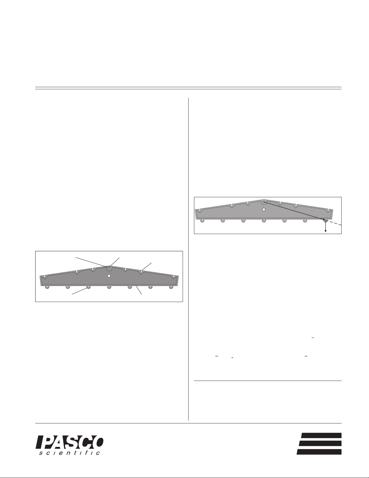
The ME-8949 Equal Arm Balance consists of a symmetric molded plastic arm attached to a low friction, freely
rotating brass axle. Masses can be suspended from the
grooves on top of the plastic arm or from the loops on the
bottom of the arm. If an outer loop or groove is used, a
mass difference of about 2% between the two ends of the
balance is detectable.
Axle with
bearings
EQUAL ARM BALANCE
MAXIMUM TOTAL MASS NOT TO EXCEED ONE KILOGRAM
ME-8949
Figure 1: Equal Arm Balance
Axis of rotation
Molded plastics bodyMass holder loops
Grooves
PASCO
scientific
Additional Equipment Required:
Use a Base and Support Rod (ME-9451), or a Universal
Table Clamp (ME-9376B) rod for basic support. Then use
a Right Angle Clamp (SE-9444) or Multi-Clamp (SE-9442)
to attach the Equal Arm Balance to the support rod.
For vertical observations with hanging masses:
– 2 SE-8703 Slotted Mass Hangers with SE-8726
Slotted Mass Set and/or
– 1 ME-9348 Mass and Hanger Set and/or
– 2 SE-8705 Hooked Mass Sets
For horizontal observations with applied forces:
– 2 SE-8716 5N Metric Spring Scales or
– 2 SE-8715 2N Metric Spring Scale or
– 2 SE-8714 1N Metric Spring Scale
Theory
The vector sum of torques with respect to the axis of rotation of an object must be zero if the object is to remain in
a state of rotational equilibrium. If a force is applied to
the Equal Arm Balance at one of the grooves or loops the
torque exerted on the Balance can be calculated.
Figure 2: Calculating Force
τ
The magnitude of the torque,
the magnitude of the moment arm vector, r and the force
vector, F and the sine of the angle between the extension
of the moment arm and the line along which the force
vector acts. Thus,
τ
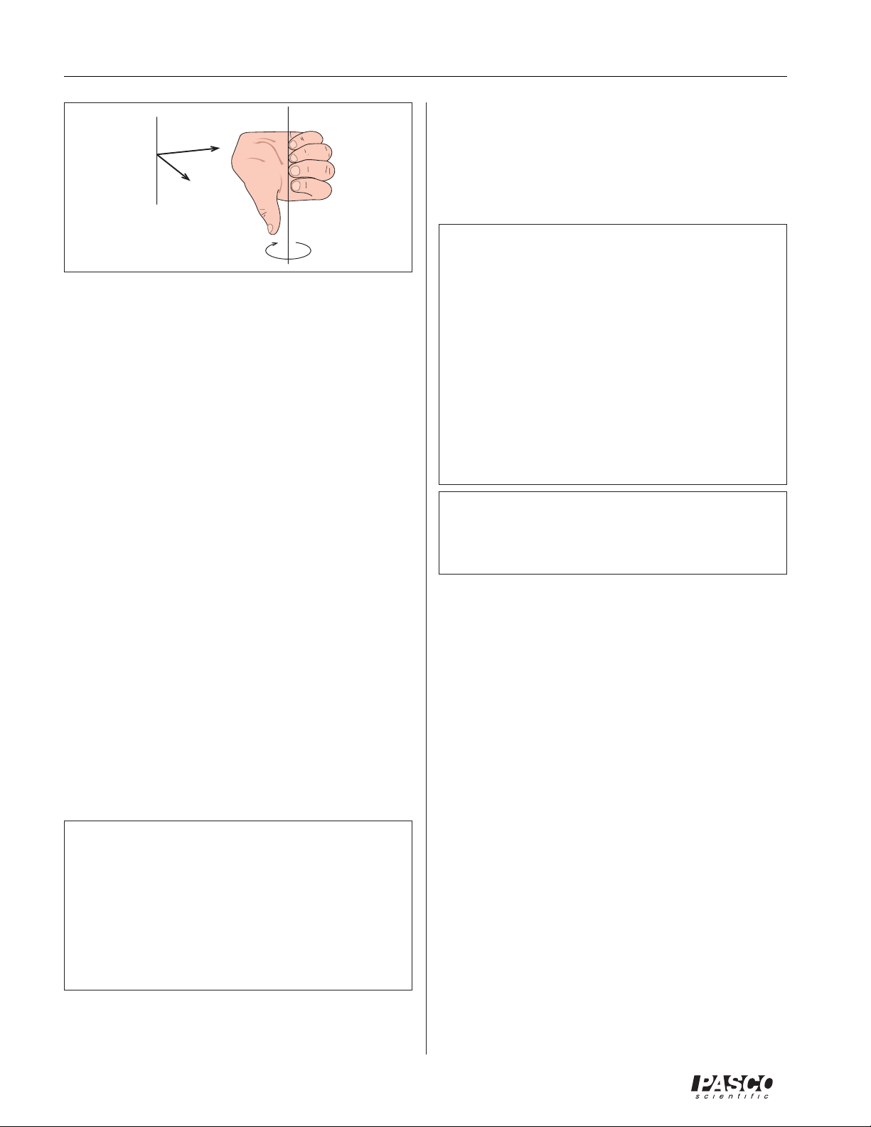
Torque is actually a vector. Its direction can be found
from the moment arm and force by using a right hand
rule. The moment arm is defined as the vector pointing
from the axis of rotation to the point of action of the
force. Lay the fingers of the right hand along
thumb will point perpendicular to the plane containing
vectors F and r. Curl your fingers toward F. The direction your fingers curl is the direction of the torque.
© 1996 PASCO scientific
Written by Priscilla Laws. Based on Units 5, 12, and 13
of the Workshop Physics Activity Guide. Published by
John Wiley and Sons (1996). Permission was granted by
the publisher for these adaptations .
, is given by the product of
=
θ
r
. Your
®
10101 Foothills Blvd. • P.O. Box 619011 • Roseville, CA 95678-9011 USA
Phone (916) 786-3800 • FAX (916) 786-8905 • email: techsupp@PASCO.com
better
ways to
teach science
Page 2
Equal Arm Balance 012-05921A
Horizontal Setup
➀ Set up a base or table clamp and support rod and at-
r
tach a multi-clamp to the top of the support rod.
F
Axis of
Rotation
Fig 3: Using Right Hand Rule to Find
Direction of Torque
Axis of Rotation
τ
Suppose the balance is mounted vertically. A standard
mass can be hung vertically from a groove or loop on one
side of the balance. An object of unknown mass can be
hung from a groove or loop at the same distance on the
other side of the Balance. If the balance doesn’t rotate
then the masses are equal. This is because the net torque
caused by the gravitational forces on one side of the balance is equal in magnitude and opposite in direction to the
net torque caused by the gravitational forces on the other
side of the balance. Thus, the Equal Arm Balance can be
used to determine a gravitational mass by comparison
with a standard mass. It can also be used to explore the
concept of torque as a vector quantity.
Setup
Vertical Setup
➀ Set up a base and support rod and attach a right angle
clamp to the support rod.
➁ Attach the Balance axle to the right angle clamp so
that the plane of the Balance is vertical.
➂ For use as an Equal Arm Balance hang masses from
loops at equal distances from the axis of rotation. Alternatively, hang masses with light string or wire loops
attached to them on each side of the center of the Balance using the upper grooves.
➤NOTE For testing the torques that result from
gravitational forces, hang a standard mass from one
of the grooves or loops on one arm of the Balance.
Place another mass at a groove or loop on the opposite side of the Balance that is a different distance
from the center. How much more or less mass is
needed to achieve a balance? What is the torque on
each side of the balance.
➁ Attach the Balance axle to the multi-clamp so that the
plane of the Balance is horizontal.
➤NOTE For testing the torques that result from
applied forces, pull with a steady force on one of
the loops on one arm of the Balance. For simplicity, pull in a direction that is in the same plane as
the balance but is perpendicular to the bottom edge
of the Balance. Exert another force at loop on the
opposite side of the balance. This force should still
be in the same horizontal plane as the Balance, but
it can be at a different distance from the center or in
a different direction. How much more or less force
is needed to balance that standard torque? Can you
calculate the magnitude and direction of the torque
on each side of the balance?
➤ CAUTION: The total mass hanging from the
Balance should never exceed one kilogram and the net
pulling force on the Balance should never exceed 10 N.
Suggested Experiments
This experiment has been adapted from Unit 5: One
Dimensional Forces, Mass, and Motion
What is mass?
Philosophers of science are known to have great debates
about the definition of mass. If we assume that mass refers somehow to “amount of stuff”, then we can develop
an operational definition of mass for matter that is made
up of particles that appear to be identical. We can assume
that mass adds up and that two identical particles when
combined have twice the mass of one particle; three particles have three times the mass; and so on. But suppose
we have two objects that have different shapes and are
made of different stuff, such as a small lead pellet and a
silver coin. How can we tell if these two entities have the
same mass?
Ideas about Mass and Its Measurement
➀ Attempt to define mass in your own words without
using the word “stuff”.
➁ How many different ways can you think of to deter-
mine whether a lead pellet and a silver coin have the
same mass?
2
®
Page 3

012-05921A Equal Arm Balance
PASCO
scientific
EQUAL ARM BALANCE
MAXIMUM TOTAL MASS NOT TO EXCEED ONE KILOGRAM
ME-8949
PASCO
scientific
EQUAL ARM BALANCE
MAXIMUM TOTAL MASS NOT TO EXCEED ONE KILOGRAM
ME-8949
➂ Suppose you find that the lead pellet and the silver
coin seem to have the same mass. How could you
create “stuff” that has twice the mass of either of the
original objects?
Using a Mass Balance
Pivot
One time honored way that people have used to compare
the mass of two objects is to put them on a balance. If
they happen to balance each other we say that the “force
(a)
(b)
of gravity” or the force of attraction exerted on them by
the earth is the same, so they must have the same mass.
Fig. 5: Equal Arm Balance & Spring Balances
Force and Lever Arm Combinations
➀ Rotate the Equal Arm Balance horizontally on the
pivot. Try pulling horizontally with each scale when
they are hooked on loops that are the same distance
from the pivot as shown in Figure 5, diagram (a)
above. What ratio of forces is needed to keep the Balance from rotating around the pivot?
Fig. 4: A common method of determining mass that
assumes two objects have the same mass if they
experience the same gravitational force.
Using a Balance to Measure an Arbitrary
Mass
➀ Explain how you might measure the passive gravita-
tional mass of an object using the balance, sand, and
standard coin.
➁ Use the Equal Arm Balance with some masses of dif-
ferent sizes and shapes to test your ideas.
This experiment has been adapted from Unit 12:
Rotational Motion
The Rotational Analog of Force – What Should It Be?
If linear equilibrium results when the vector sum of the
forces on an object is zero (i.e. there is no change in the
motion of the center of mass of the object), we would like
to demand that the sum of some new set of rotational
quantities on a stationary non-rotating object also be zero.
By making some careful observations you should be able
to figure out how to define a new quantity which is analogous to force when it comes to causing or preventing rotation. For this set of observations you will need:
• 1 Equal Arm Balance
• 1 clamp stand (to hold the Balance)
• 2 spring scales, 5 N
• 1 ruler
➁ Try moving one of the spring scales to some other
loop as shown in Figure 5, diagram (b). Now what
ratio of forces is needed to keep the Balance from rotating? How do these ratios relate to the distances?
Try this for several different situations and record
your results in Table 1 below.
Table 1
Original Original Balancing Balancing
Force (N) Distance (cm) Force (N) Distance (cm)
1
2
3
4
➂ What mathematical relationship between the original
force and distance and the balancing force and distance give a constant for both cases? How would you
define the rotational factor mathematically? Cite evidence for your conclusion.
➃ Show quantitatively that your original and final rota-
tional factors are the same within the limits of experimental uncertainty for all four of the situations you set up.
The rotational factor that you just discovered is officially
known as torque and is usually denoted by the Greek letter τ (“tau” which rhymes with “cow”). The distance
from the pivot to the point of application of a force is defined as the lever arm for that force.
®
3
Page 4

Equal Arm Balance 012-05921A
F
F
F2F
F4F5F
F
This experiment has been adapted from Unit 13:
Angular Momentum and Torque as Vectors
Observation of Torque when
and r are not
Perpendicular
In Experiment 2, you “discovered” that if we define
torque as the product of a lever arm and perpendicular
force, an object does not rotate when the sum of the
torques acting on it add up to zero. However, we didn’t
consider cases where
and r are not perpendicular, and
we didn’t figure out a way to tell the direction of the rotation resulting from a torque. Let’s consider these complications by generating torques with spring balances and an
Equal Arm Balance once more. For this activity you’ll need:
• 1 Equal Arm Balance
• 1 clamp stand (to hold the Balance)
• 2 spring scales, 5 N
• 1 ruler
• 1 protractor
Torque as a Function of Angle
➀ Suppose you were to hold one of the scales at an angle
o
of 90
with respect to the lever arm, rh, and pull on it
with a steady force. Meanwhile you can pull on the
other scale at several angles other than 90
lever arm, r
, as shown below. Would the magnitude
app
o
from its
of the balancing force be less than, greater than, or
equal to the force needed at 90o? What do you predict? Explain.
➁ You should determine exactly how the forces com-
pare to that needed at a 90
force for at least four different angles and figure out a
mathematical relationship between F, r, and θ. Set up
a spreadsheet to do the calculations shown in Table2
below . Hint: Should you multiply the product of the
measured values of r and F by sinθ or by cosθ to get
a torque that is equal in magnitude to the holding
torque?
o
angle. Determine this
r
h
EQUAL ARM BALANCE
MAXIMUM TOTAL MASS NOT TO EXCEED ONE KILOGRAM
φ
1
h
θ
ME-8949
r
1
Holding torque: τ
1
r
r
app
PASCO
h
3
scientific
θ
2
φ
2
1
2
Fig 5: Torque at an angle
➂ Within the limits of uncertainty, what is the most plau-
sible mathematical relationship between τ and
and θ?
r
, F,
Limited Warranty
PASCO scientific warrants this product to be free from
defects in materials and workmanship for a period of one
year from the date of shipment to the customer. PASCO
will repair or replace, at its option, any part of the product
which is deemed to be defective in material or workmanship. This warranty does not cover damage to the product
caused by abuse or improper use. Determination of
whether a product failure is the result of a manufacturing
defect or improper use by the customer shall be made
solely by PASCO scientific. Responsibility for the return
of equipment for warranty repair belongs to the customer.
Equipment must be properly packed to prevent damage
and shipped postage or freight prepaid. (Damage caused
by improper packing of the equipment for return shipment will not be covered by the warranty.) Shipping
costs for returning the equipment, after repair, will be
paid by PASCO scientific.
Holding
Torque
rh(m) Fh(N) τh(Nm) r
(m) F
app
Table 2
(N) θ(deg) θ(rad) cosθ sinθ r
app
Applied
Torque
appFapp
cosθ r
appFapp
sinθ
®
4
 Loading...