

Page 1
Instruction Manual and
Experiment Guide for the
PASCO scientific
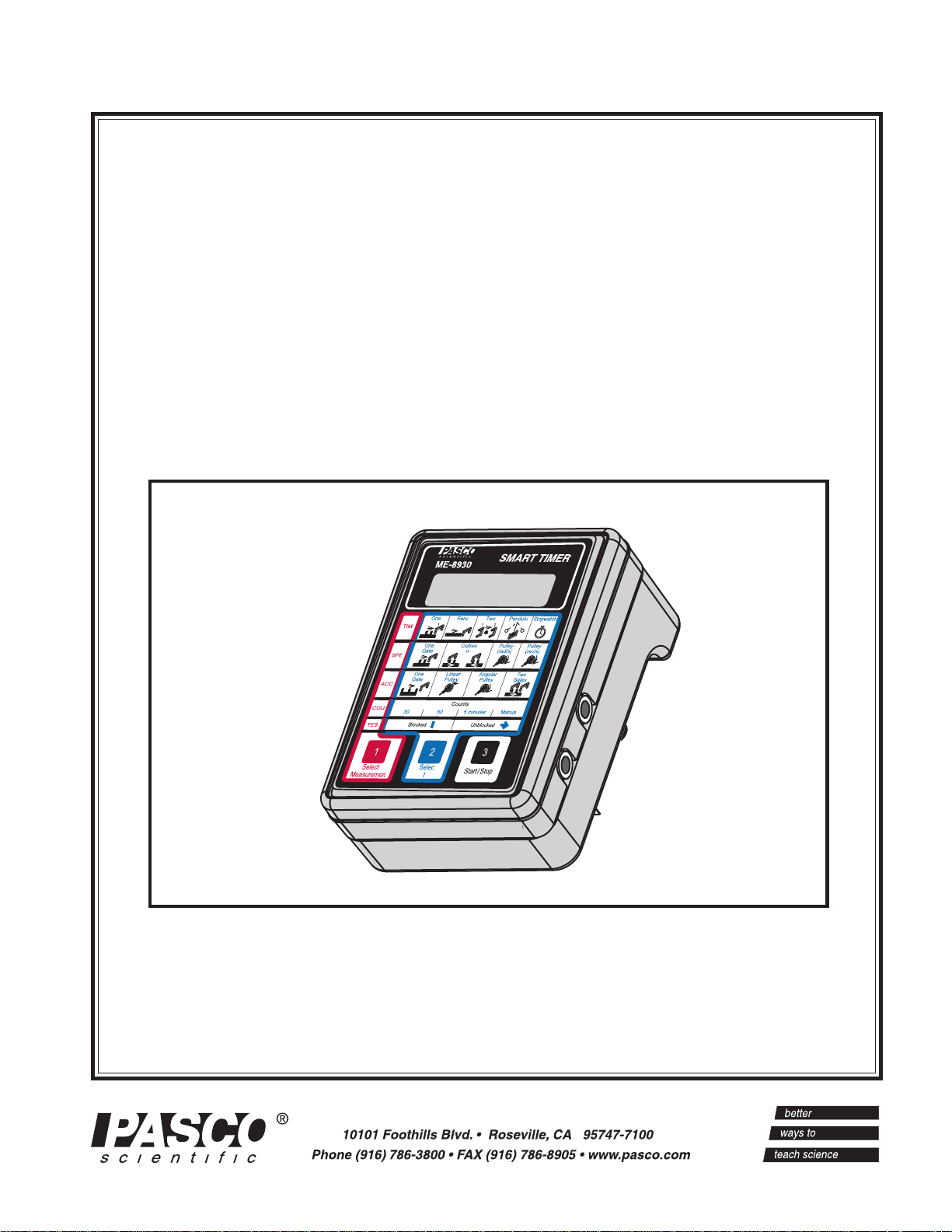
Model ME-8930
SMART TIMER
012-06734A
09/98
Plane4
© 1998 PASCO scientific $7.50
Page 2

Smart Timer 012–06734A
Page 3

01206734A Smart Timer
Table of Contents
Section Page
Table of Contents ..........................................................................................................................i
Copyright, Warranty, and Equipment Return ................................................................................ ii
Introduction ................................................................................................................................. 1
Equipment ................................................................................................................................... 3
Operating the Smart Timer .......................................................................................................... 4
Smart Timer Modes of Operation ................................................................................................ 4
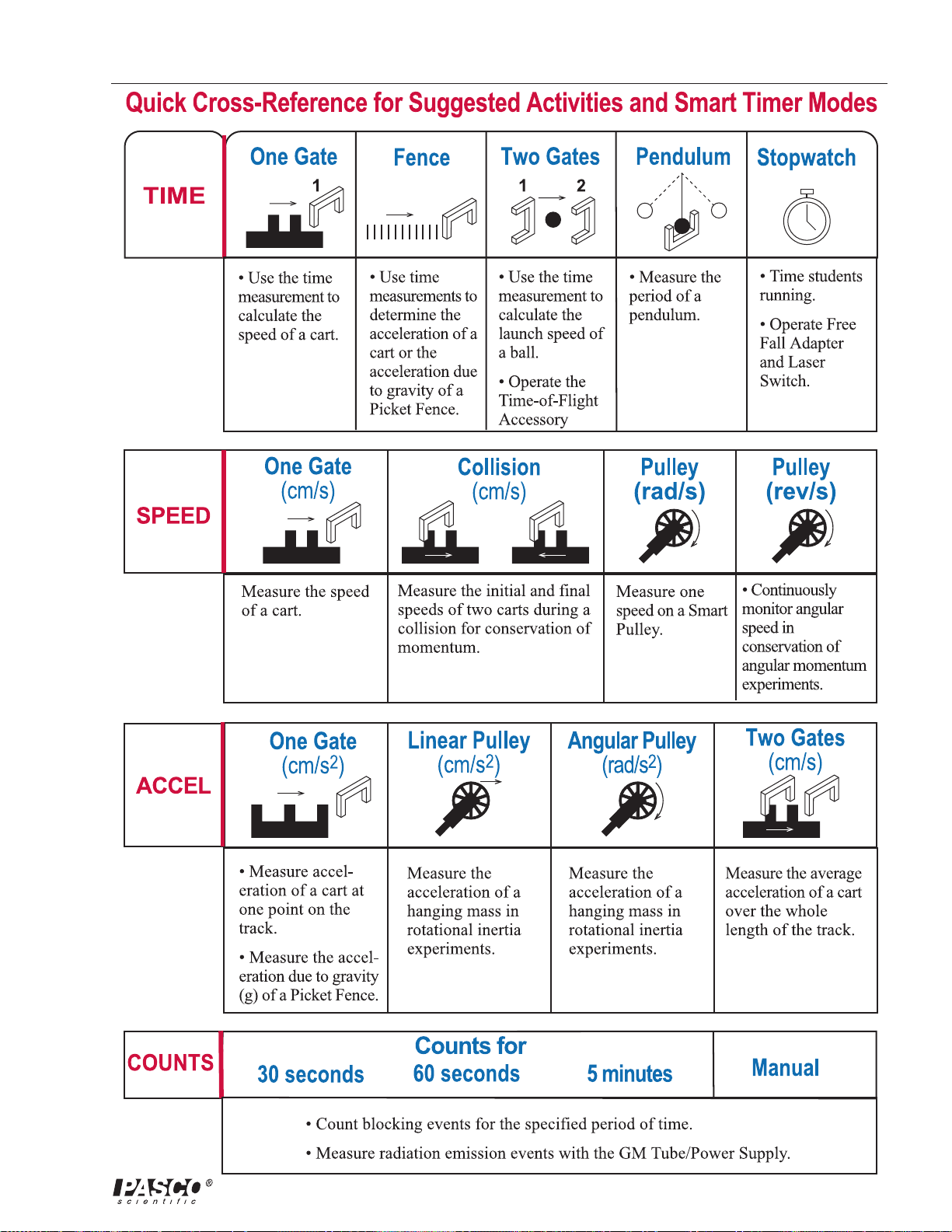
Quick Cross-Reference for Suggested Activities and Smart Timer Modes .............................. 5
Time Modes ....................................................................................................................... 6
Speed Measurement Modes ................................................................................................. 7
Table 1: Summary of Timing Modes................................................................................ 89
Acceleration Measurement Modes ..................................................................................... 10
Count Modes .................................................................................................................... 10
Test Mode ........................................................................................................................ 11
Timing Diagrams ................................................................................................................ 11
LOCK Switch: ................................................................................................................... 11
Caring for the Smart Timer ........................................................................................................ 12
Specifications ............................................................................................................................. 12
Accessory Options ...................................................................................................................... 12
Troubleshooting ........................................................................................................................ 14
Experiment One: Acceleration of Gravity ................................................................................... 15
Experiment Two: Newtons Second Law ................................................................................... 17
Experiment Three: Conservation of Momentum In Collisions .................................................... 19
Experiment Four: Conservation of Angular Momentum ............................................................. 25
Other Suggested Experiments ..................................................................................................... 31
Technical Support ......................................................................................................... back cover
i
Page 4

Copyright, Warranty, and Equipment Return
PleaseFeel free to duplicate this manual
subject to the copyright restrictions below.
Copyright Notice
The PASCO scientific 012-06734A Smart Timer
manual is copyrighted and all rights reserved. However,
permission is granted to non-profit educational
institutions for reproduction of any part of the manual
providing the reproductions are used only for their
laboratories and are not sold for profit. Reproduction
under any other circumstances, without the written
consent of PASCO scientific, is prohibited.
Limited Warranty
PASCO scientific warrants the product to be free from
defects in materials and workmanship for a period of
one year from the date of shipment to the customer.
PASCO will repair or replace at its option any part of
the product which is deemed to be defective in
material or workmanship. The warranty does not
cover damage to the product caused by abuse or
improper use. Determination of whether a product
failure is the result of a manufacturing defect or
improper use by the customer shall be made solely by
PASCO scientific. Responsibility for the return of
equipment for warranty repair belongs to the
customer. Equipment must be properly packed to
prevent damage and shipped postage or freight
prepaid. (Damage caused by improper packing of the
equipment for return shipment will not be covered by
the warranty.) Shipping costs for returning the
equipment after repair will be paid by PASCO
scientific.
Equipment Return
Should the product have to be returned to PASCO
scientific for any reason, notify PASCO scientific by
letter, phone, or fax BEFORE returning the product.
Upon notification, the return authorization and
shipping instructions will be promptly issued.
ä
NOTE: NO EQUIPMENT WILL BE
ACCEPTED FOR RETURN WITHOUT AN
AUTHORIZATION FROM PASCO.
When returning equipment for repair, the units must
be packed properly. Carriers will not accept
responsibility for damage caused by improper
packing. To be certain the unit will not be damaged in
shipment, observe the following rules:
➀ The packing carton must be strong enough for the
item shipped.
➁ Make certain there are at least two inches of packing
material between any point on the apparatus and the
inside walls of the carton.
➂ Make certain that the packing material cannot shift in
the box or become compressed, allowing the
instrument come in contact with the packing carton.
Address: PASCO scientific
10101 Foothills Blvd.
Roseville, CA 95747-7100
Phone: (916) 786-3800
FAX: (916) 786-3292
email: techsupp@pasco.com
web: www.pasco.com
ii
Page 5

012–06734A Smart Timer
Introduction
The PASCO ME-8930 Smart Timer is an accurate, versatile digital timer and
measurement system for the student laboratory. The Smart Timer offers 0.1 ms timing
resolution and an easy-to-use memory function. The Smart Timer measures several types
of events detected with PASCO’s digital sensors, including speed and acceleration using
standard photogates. The PASCO ME-9387 Smart Pulley, the ME-9207B Free Fall
Adapter, the ME-6810 Time-of-Flight Accessory, or the ME-9259A Laser Switch also
work with the Smart Timer. The Smart Timer counts radiation emission events detected
with the SN-7927 G-M Tube/Power Supply or the SE-7997 G-M Tube. The Smart Timer
features two input channels and a 2-line, 16-character alphanumeric liquid crystal display
that indicates the operating mode and experimental results.
Features:
The Smart Timer’s memory function makes it easy to time events that happen in rapid
succession, such as a Dynamics Cart passing twice through the photogate, once before
and then again after a collision. The 0.1 ms resolution is especially useful in some
experiments, such as measuring velocity or acceleration during free fall. The Smart
Timer can calculate velocity before and after a collision between two carts using a single
timer. With the new fence design and sensing logic, parallax errors are eliminated and
timing accuracy is improved considerably over existing timing options. The Smart
Timer’s internal microcontroller also eliminates the problem of incorrect readings due to
multiple passes through the same photogate by “understanding” the type of measurement
selected and ignoring multiple passes.
The Smart Timer has many different options for timing and calculating values based on
inputs from a variety of sensors. The graphics on the keypad aid in the selection of the
appropriate timing mode. Options include One or Two Gates, Fence, and Pendulum
modes. These modes allow you to measure the speed of an object as it passes through the
photogate or between two photogates, or to measure the period of a pendulum. The
stopwatch mode lets you use the timer as an electronic stopwatch.
The Smart Timer can measure speed and acceleration for both linear and rotational
motion experiments. Alternatively, the time can be measured directly, and the speed and
acceleration can then be calculated by the student. The speed and acceleration
measurement features can be enabled or disabled using a switch inside the Smart Timer.
Use With Photogates:
The Smart Timer is optimized for use with PASCO’s ME-9204B Accessory Photogate
(available separately). These narrow-beam infrared photogates plug directly into the
Smart Timer and are used to provide the timing signals. An LED in one arm of the
photogate emits a narrow infrared beam. As long as the beam strikes the detector in the
opposite arm of the photogate, the signal to the timer indicates that the beam is
unblocked. When an object blocks the beam so it doesn’t strike the detector, the signal to
the timer changes.
1
Page 6

Smart Timer 012–06734A
In One Gate Mode, a single photogate lets you measure the time, velocity, or acceleration
of a fence as it passes through the photogate. Two photogates are used for collision
experiments using one or two carts or for experiments where the velocity of a cart must be
measured at two different points. In Two Gate Mode, two photogates are used and the
time to travel between the two can be measured. This mode can also be used to measure
time of flight using the ME-6810 Time-of-Flight Accessory.
Use with the Smart Pulley:
For rotary motion studies, the ME-9387 Smart Pulley (available separately) is ideal. It
combines a photogate with a pulley, and when used with the Smart Timer, allows direct
measurement of angular speed and acceleration. When used with a string connected to a
glide or Dynamics Cart, the Smart Timer and Smart Pulley can be used to determine
2
linear acceleration (cm/s
) as well.
➤ Note: The use of pulleys with different diameters and/or different number of spokes
than the Smart Pulley or the ME-9450 Super Pulley will give incorrect results in the speed
and acceleration calculations.
Power Options:
The Photogate Timer can be powered using the included 9VDC adapter. It will also run
on 4-AA size, 1.5 volt alkaline batteries which will provide over 100 hours of operation in
typical use.
Experiments:
Four copy-ready experiments and 9 additional suggested experiments are included in this
manual, showing a variety of ways to use the Smart Timer. The equipment requirements
vary for different experiments. For many of the experiments, you will need a Dynamics
Track and Dynamics Carts. Some experiments also require two ME-9204B Accessory
Photogates or the ME-9387 Smart Pulley. Check the equipment requirements listed at the
beginning of each experiment.
2
Page 7
012–06734A Smart Timer
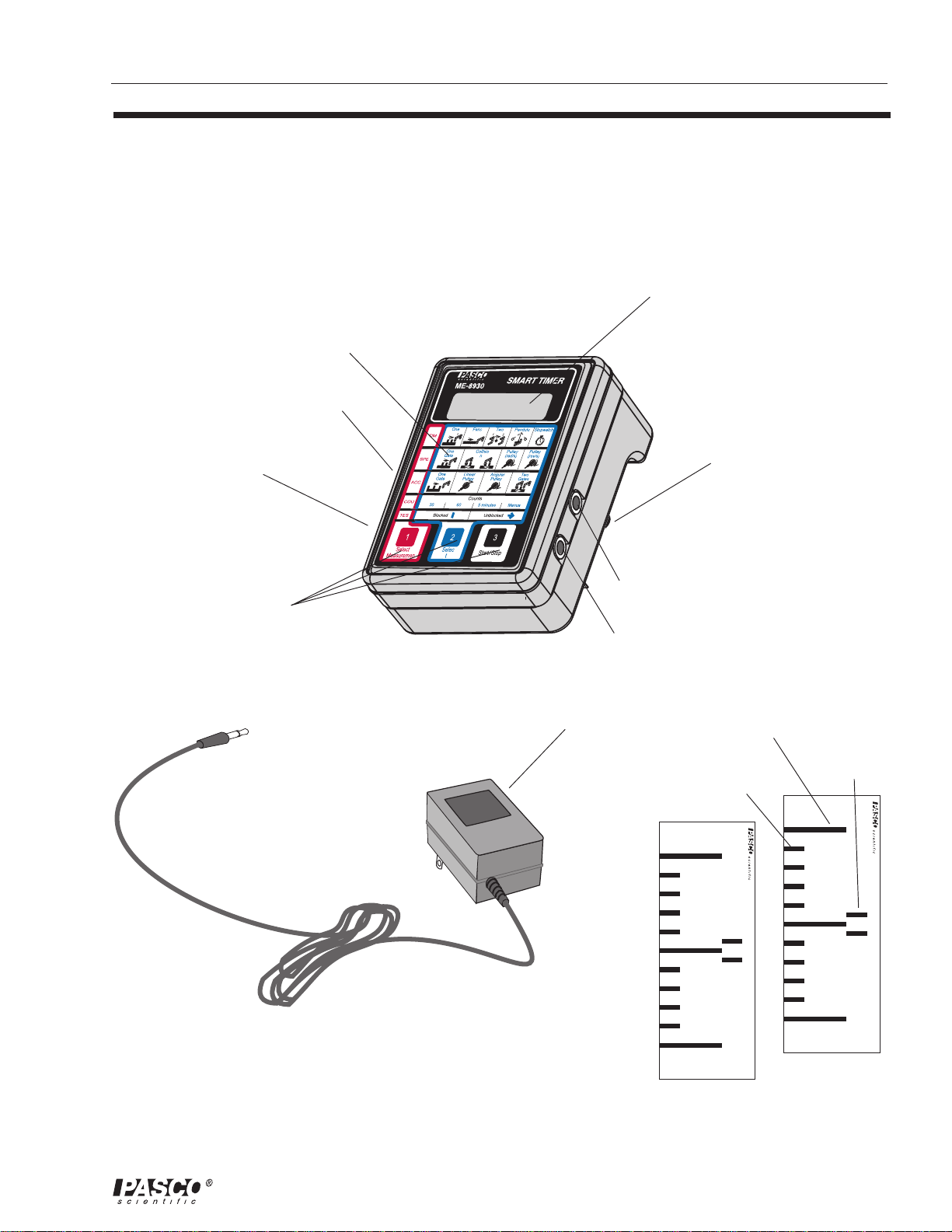
Equipment
Included:
Smart Timer
Smart Timer Picket Fences (2)
9 VDC adapter
mode illustrations
liquid crystal display
connector for 9VDC adapter
(side panel))
on/off switch
(side panel)
touchpad keys
Plane4
input channel 2
input channel 1
9 VDC adapter
battery compartment
(bottom panel)
5 cm fence
1 cm flag
1 cm fence
Figure 1
Included equipment
Smart Timer Picket Fence
Smart Timer Picket Fence
Smart Timer Picket Fences
3
Page 8
Smart Timer 012–06734A
Plane4
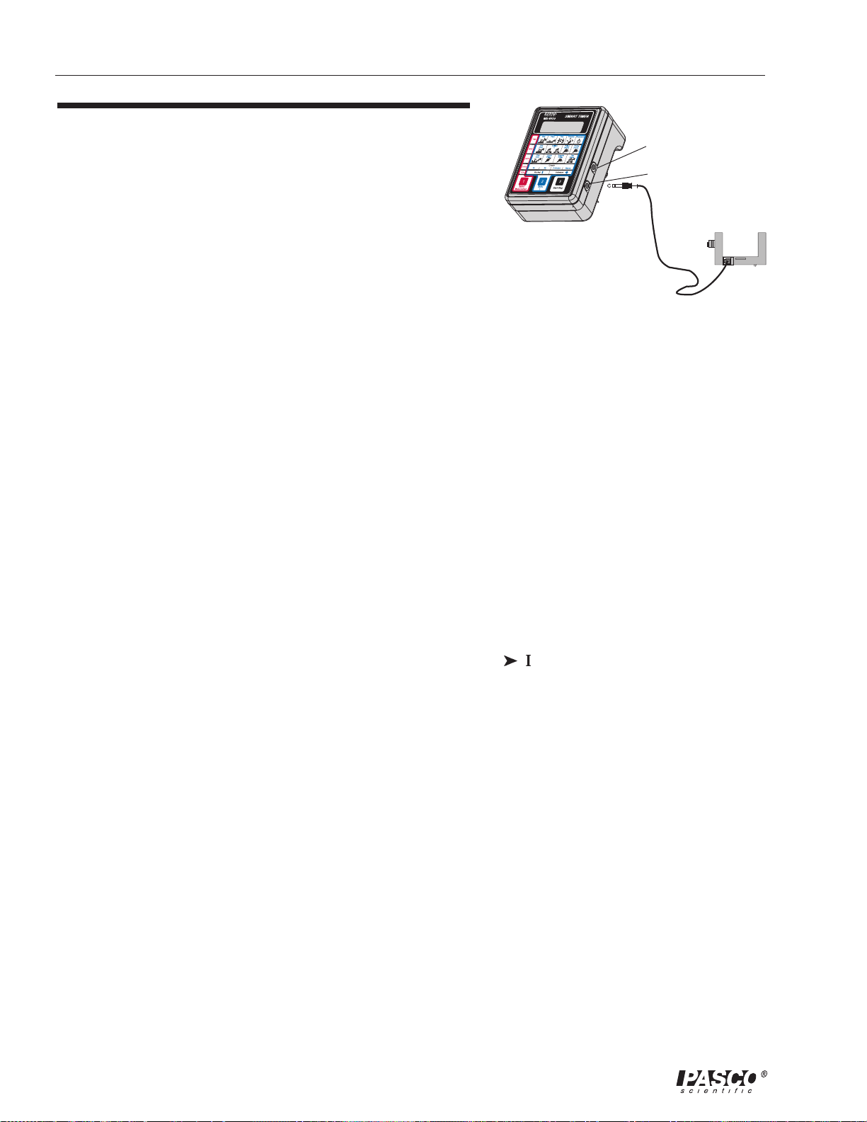
Operating the Smart Timer
input channel 2
input channel 1
1. Plug the ¼-inch phone plug from the photogate into the
Smart Timer’s input channel 1 or 2 (see Figure 2). For all
experiments using a single photogate or pulley, either of the
two available jacks may be used interchangeably. For all
other modes see the individual descriptions below.
2. Plug the 9 VDC power adapter into the small receptacle on
the side of the timer and into a standard 110 VAC, 60 Hz
wall outlet.
3. Position the photogate head so the object to be timed will
pass through the arms of the photogate, blocking the
photogate beam. Loosen the clamp screw if you want to
change the angle or height of the photogate, then tighten it
securely.
4. Slide the power switch to the ON position. The Smart
Timer will “beep” and show PASCO scientific on the
display. From this point, the three-step setup of the Smart
Timer is easy:
1. Press the Select Measurement key until the
desired measurement type is displayed on the top
line of the display. Note that the menu rolls over to
the beginning after the last type is selected.
2. Press the Select Mode key until the measurement
mode is displayed after the measurement type.
You cannot begin a measurement until both the
type and mode have been selected.
3. Once a complete measurement has been selected,
press Start/Stop to begin. You will hear a “beep”,
and a asterisk (*) will appear on the second line of
the display. In most modes, the (*) indicates that
the Smart Timer is now waiting for an event to
occur, like a fence passing through a photogate.
5. If an event occurs, the Smart Timer beeps again, displays a
result, and the (*) disappears. Pressing Start/Stop before an
event occurs will remove the (*) and allow you to change
the measurement type.
Figure 2
Connecting the photogate to the Smart
Timer
➤ Note: Smart Timers shipped to certain
locations are supplied with a transformer
for 220/240 VAC, 50 Hz power.
ä
Important Setup Note:
The Smart Timer incorporates a feature to
increase the battery lifetime. The photogate
turns on only when Start/Stop is pressed
to start an experiment. Photogate power is
turned off when the measurement is
complete or the operator presses Start/
Stop. The exception is the Test mode in
which photogate power is turned on as
soon as the display reads Test:Gates and is
not turned off until Select Measurement is
pressed again. Setup for the experiment is
often best accomplished in Test:Gates
mode.
Smart Timer Modes of Operation
The Smart Timer has 18 modes of operation organized into five
groups: Time, Speed, Acceleration, Counts, and Test. A
4
Page 9
012–06734A Smart Timer
5
Page 10

Smart Timer 012–06734A
summary of the mode suggested for a given experimental activity can be found on page 5
(Quick Cross-Reference for Suggested Activities and Smart Timer Modes). Refer to the
timing diagrams in Table 1 (pages 8 and 9) for a detailed look at how the Smart Timers
times events on its input(s) and an explanation of how speed and acceleration calculations
are performed internally.
The following are detailed descriptions of the Smart Timer’s modes of operation.
Time Modes
One Gate: In One Gate mode, timing begins when the beam is first blocked and
continues until the beam is blocked again. This mode can be used to measure the speed of
an object as it passes through the photogate. If an object of length L blocks the photogate
for a time t, the average velocity of the object as it passed through the photogate was L/t.
Fence: In Fence mode, the timer measures the time between successive interruptions of
the photogate. Timing begins when the beam is first blocked and continues until the
beam is unblocked and then blocked again. The Smart Timer can remember ten such
interruptions and will allow the user to scroll through the times using either the Select
Measurement or the Select Mode keys. Pressing the Start/Stop once will allow another
measurement type to be selected. Pressing it twice begins a new Fence Mode
measurement. Note that once a measurement has begun with an initial block of the
photogate, the Smart Timer will continue to time until ten interruptions are counted before
stopping the measurement and displaying the result. Pressing Start/Stop will stop the
measurement, and any recorded times will be displayed.
➤ Note: The
picket fence
supplied with the
Smart Timer is
designed to
increase timing
accuracy when
used with
photogates. The
fence has three
sections: the 1 cm
flag, the 5 cm
fence, and the 1
cm fence; one of
these must be
aligned with the
photogate light
path before the
experiment can
proceed.
Two Gates: In this mode, the Smart Timer measures the time between blocking two
photogates. This mode is useful for not only air tracks and Dynamics Tracks but also with
the ME-6810 Time-of-Flight Accessory. In this mode, you must plug the photogate you
expect to encounter first into input channel 1, and the second photogate into input
channel 2.
Pendulum: In Pendulum mode, the timer measures the period of one complete
oscillation. Timing begins as the pendulum first cuts through the beam. The timer
ignores the next interruption, which corresponds to the pendulum swinging back in the
opposite direction. Timing stops at the beginning of the third interruption, as the
pendulum completes one full oscillation. Press the Start/Stop key again to begin a new
timing cycle.
Stopwatch: The Manual mode is actually a dual-use function. It provides a means of
manually timing events (like a using a Stopwatch) by pressing the Start/Stop key. It also
allows timing of events using the ME-9207B Free-Fall Adapter and the ME-9259A Laser
Switch, which function via a block/unblock sequence.
Using the Stopwatch: Enter Stopwatch mode and press the Start/Stop key. The
Smart Timer will beep and a “*” will appear on the second line of the LCD. Press
the Start/Stop key again to start the timer. Press the Start/Stop key to stop timing
and display the elapsed time. Press the Start/Stop key again. The old result is
6
Page 11

012–06734A Smart Timer
cleared and the “*” reappears. This RESET-START-STOP sequence is repeated for
each new elapsed time. Whenever the “*” is not showing, the mode may be
changed.
Using the Alternate Timing Function: Connect an appropriate accessory to input
channel #1 or #2. Enter Stopwatch mode and press the Start/Stop key. The Smart
Timer will beep and a “*” will appear on the second line of the LCD. At this time
the accessory will be powered. By blocking and unblocking the beam in the case of
the Laser Switch, or by dropping the steel ball in the case of the Free Fall Adapter,
the elapsed time will be measured. The Smart Timer will resolve 100 microseconds
in the alternate timing mode.
➤ Notes about the Stopwatch Mode:
1. Although it is possible to use older style fences in the alternate timing function to
obtain photogate beam block times, the Smart Timer will provide much higher
accuracy when used with the included fences and the standard timing modes.
2. Two photogates cannot be plugged into the Smart Timer when you are using a
photogate to start and stop the timer. A single photogate can be plugged into channel
#1 or #2 to start and stop the timer. But if two photogates are plugged in, when one
gate is blocked, the other gate immediately is counted as an unblock, and the timer
will display 0.0001 seconds, regardless of the length of time the first photogate is
blocked.
3. You cannot start the timing with the Start/Stop key and end it with a photogate
block or vice versa.
➤ Note:
The stopwatch
function is not a
precision timing
mode and is
therefore most
useful for events
that are longer
than one second.
The accuracy of
the stopwatch is
+/-10
milliseconds.
➤ Hint:
For easier
alignment of the
laser with the
Laser Switch, use
the Test:Gates
mode.
4. If a photogate is plugged in and blocked when you try to use the Start/Stop key as a
stopwatch, the Smart Timer will be timing the photogate and waiting for the
photogate to become unblocked. So when you push the Start/Stop key, the asterisk
disappears and when you push the Start/Stop key again, the asterisk reappears. No
time is displayed until the photogate is unblocked.
Speed Modes
One Gate: In this mode a 1 cm flag passes through the photogate. The Smart Timer
measures the time and calculates the average speed in cm/s.
Collision: In this mode either one or two carts and one or two photogates can be used for
a collision experiment. Once Start/Stop is pressed, the Smart Timer waits for the first
collision and begins timing. The Smart Timer stops timing when two carts have passed
through their respective photogates twice. Timing can always be stopped manually by
pressing Start/Stop and the Smart Timer will display speed(s) based on the information it
has (you will need to press Start/Stop for single cart collisions). The display will present
the results in the following format:
1: xx.x,yy.y
2: xx.x,yy.y
The first number represents the input jack and the following two numbers indicate the
initial speed (xx.x) and final speed (yy.y), respectively.
7
Page 12
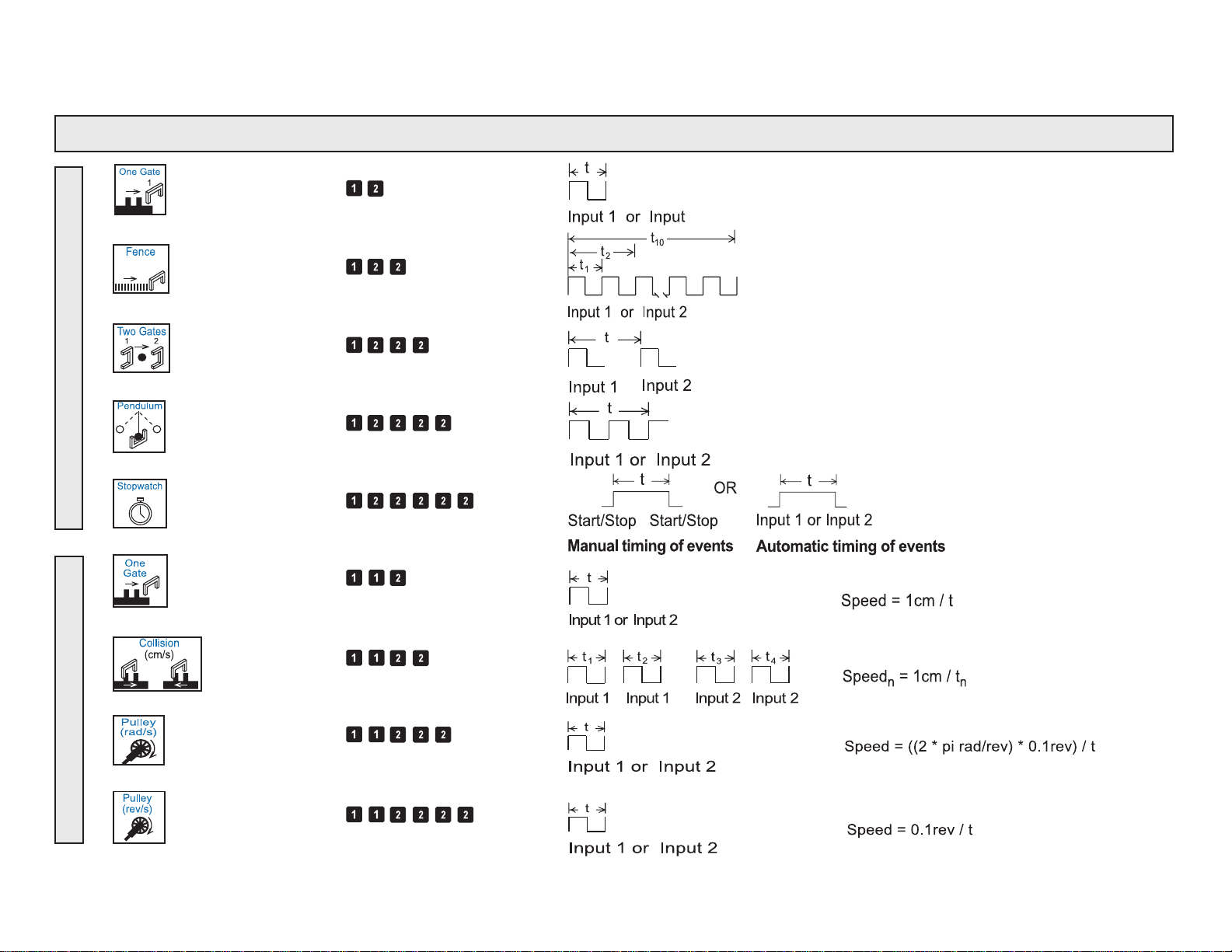
Table 1. Summary of Smart Timer Modes
Type Modes Key Sequence* Timing Diagram** Calculation Algorithm
One Gate
Fence
Two Gates
TimeSpeed
Pendulum
Stop Watch
One Gate (cm/s)
Collision (cm/s)
Pulley (rad/s)
Pulley (rev/s)
Page 13

Acceleration
One Gate
Linear Pulley
Angular Pulley
Two Gates
30 seconds
60 seconds
Counts
Test
5 minutes
Manual
One Gate
* The key sequences shown
are valid in the initial or
power-on situation only.
Page 14

Smart Timer 012–06734A
Pulley (rad/s): The Smart Timer will measure the speed of a pulley passing through a
photogate in units of radians/second. One measurement will be taken each time the Start/
Stop switch is pressed. The Smart Timer cannot differentiate between clockwise and
counterclockwise directions. Note that, as in many other modes, if a “*” shows in the first
character position of the second line, the Smart Timer is actively waiting for an external
timing event to occur. If the “*” is not showing, the Timer measurement mode may be
changed. This mode has a minimum speed requirement. The photogate must be blocked
twice within two seconds to obtain a valid reading, translating to a minimum speed of
0.31 rad/s.
Pulley (rev/s): Besides displaying in different units, this mode uses the display differently
than in the radians/second measurement. The display provides a real-time measurement of
the speed of the pulley by updating once per second. Once a speed is displayed, press the
Start/Stop key to freeze the display. The Smart Timer indicates that the measurement is
frozen by displaying a “!” in the first column. Press Start/Stop to erase the “!” and start
collecting new measurements. Any time the first column is blank or has a “!” displayed,
the type of measurement being done can be changed by pressing the Select
Measurement or Select Mode keys. To move to a different measurement, press Start/
Stop again. Like the radians/second measurement, there is a two-second maximum time
for two photogate blocks, translating to a minimum speed of 0.05 rev/s. Also note that
accuracy decreases rapidly as pulley speeds increase above 600 rpm. At 600 rpm,
accuracy is 1%.
Acceleration Modes
One Gate: The Smart Timer uses the time measurement between two equally spaced (5
cm) block/unblock/block sequences to calculate average acceleration. In activities using
the Smart Timer Picket Fence, the Picket Fence must be positioned so that the photogate
blocks only the 3-bar segment (5cm fence) of the Picket Fence. Note that the Smart Timer
is able to discern between acceleration (positive number) and deceleration (negative
number).
Linear Pulley: In this mode, the Smart Timer converts rotary motion of a PASCO pulley
2
to an equivalent linear acceleration in cm/s
.
Angular Pulley: In this mode, the Smart Timer converts rotary motion of a PASCO
2
pulley to an equivalent angular acceleration in rad/s
.
Two Gates: When two photogates are placed an arbitrary distance apart, the average
acceleration between the two can be calculated. In this mode, the inputs used are not
arbitrary. The first photogate to be encountered must be connected to input #1 and the
second to input #2.
Count Modes:
30 Seconds: The timed 30-second count mode will count high-to-low voltage transitions
on either input and display them on the second line of the liquid crystal display. After the
counting period is over, the Smart Timer will beep once, remove the power to the external
device, and freeze the display. Pressing Start/Stop erases the old count and begins a new
10
Page 15

012–06734A Smart Timer
timing interval. If you wish to stop the count during a timing interval, press Start/
Stop. The display will freeze the current count and the “*” will disappear from the
first column. At this time you may select a new measurement or start a new timing
interval. The maximum counting rate for any of the counting modes is 5,000 counts
per second and the maximum count is 9,999,999.
60 Seconds: Other than timing the count interval for 60 seconds, the 60-second count
mode is the same as the 30-second mode.
5 Minutes: Other than timing the count interval for 5 minutes, the 5-minute count mode
is the same as the 30-second mode
Manual: Manual mode will count high-to-low voltage transitions on either input and
display them on the second line of the liquid crystal display. There is no time limit for
counting, however the upper limit on the number of total counts is still 9,999,999. Each
count will be accompanied by a short beep. Used with a PASCO SN-7927 G-M Tube/
Power Supply, this mode is useful for group demonstrations to show the random nature
of atomic disintegration and the inverse-square relationship between number of
disintegration’s detected and distance from the radioactive source.
Test Mode
Gates: In the Test:Gates measurement, the external measuring accessory is powered as
long as the top line of the display reads Test:Gates. This mode is useful for experiment
setup or for testing accessory photogates, G-M tubes, or other Smart Timer accessories.
Pressing the Select Measurement key will exit the test mode and remove power to the
external device. The display graphics depict a blocked photogate as a vertical line and an
unblocked photogate as an arrow.
Timing Diagrams
The timing diagrams on pages 8 and 9 show the interval, t, that is measured in each
timing mode. In each diagram, an elevated line corresponds to the photogate being
blocked, and a depressed line corresponds to the photogate being unblocked. The
calculation modes assume the use of a fence of fixed width (1 cm or 5 cm) or a pulley
having a diameter (groove to groove) of 4.8 cm and 10 spokes, such as the Super Pulley
or Smart Pulley.
LOCK Switch
The internal LOCK switch provides a way to temporarily lock
out speed and acceleration modes. To access the LOCK
switch, turn the power off, and remove the bottom half of the
Smart Timer case as if you were going to replace the batteries.
Look along the lower edge of the printed circuit board, and
note the LOCK switch button at the edge (Figure 3). The circuit
board also has the words “LOCK” and “UNLOCK” printed
along the same edge. Moving the switch to the LOCK position
will cause the display to read MODE UNAVAILABLE
whenever speed or acceleration modes are selected.
circuit board
Figure 3
Location of the LOCK switch on the circuit
board.
LOCK switch
11
Page 16

Smart Timer 012–06734A
Caring for the Smart Timer
• Do not use a pointed object (such as a pen) to press the keypad buttons. Wrap the
Smart Timer separately when transporting it with other items. The transparent
covering over the keypad can be creased by a fingernail or other sharp object.
• Clean the keypad with a soft cloth and mild detergent, avoiding hard rubbing of the
transparent window.
• Do not leave the Smart Timer exposed to direct sunlight except for brief periods.
Strong ultraviolet light can damage the Smart Timer display.
• Remove the batteries prior to storage for more than one month. Batteries can leak
and damage the internal circuitry, especially if the batteries are old.
• For best results, use alkaline batteries. Rechargeable NiCad batteries may be used,
but the operating time between charges is much shorter than the lifetime of alkaline
batteries.
Specifications
Resolution: The basic timing resolution of the Smart Timer is 100 microseconds in all
modes except Stopwatch, which is 10 ms.
Calculated Values: Calculated values are displayed to one or two decimal places with
typical accuracy being +/- 1 in the least significant digit. For extremely high speeds (such
as might be generated by hand spinning a Super Pulley), accuracy is degraded for
calculated parameters because of the very short timing intervals involved.
Maximum Output Power: The Smart Timer allows many different accessories to be
used as inputs. The total 5-volt load (both inputs added together) that can be
accommodated is 180 mA, maximum.
Accessory Options
The following PASCO accessories are available to help extend the utility of the Smart
Timer. See the current PASCO catalog for more information.
Accessory Photogate (ME-9204B): The stereo phone plug of the Accessory Photogate
plugs into either of the phone jacks on the side of the Smart Timer, giving you the option
of two identical photogates operating from a single timer. (Some of the experiments in
this manual require the use of a Smart Timer with two Accessory Photogates.)
12
Page 17

012–06734A Smart Timer
Time-of-Flight Accessory (ME-6810): The Timer-of-Flight Accessory facilitates the
accurate measurement of the flight time of a ball launched by a PASCO projectile
launcher. See page 33 (Time of Flight and Initial Velocity and Figure 9.1) for details of
the setup.
Free Fall Adapter (ME-9207B): The Free Fall Adapter facilitates easy and accurate
measurements of the acceleration of gravity. It comes with everything you need,
including two steel balls (of different size and mass), a release mechanism, and a receptor
pad. The release mechanism and the receptor pad automatically trigger the Smart Timer,
so you get more accurate measurements of the free fall time of the steel ball. See page 34
(Determining the acceleration due to gravity (g) with the Free Fall Adapter and Figure
10.1) for details of the setup.
Laser Switch (ME-9259A): This highly collimated photodetector is identical to a
photogate, except that a laser (available separately) is used as the light source. With the
Laser Switch, the motion of objects that are too big to fit through a standard photogate
can be measured. Thus, you can measure the period of a bowling ball pendulum or the
velocity of a car, for example.
G-M Tube/Power Supply (SN-7927): The G-M Tube Power Supply is a Geiger-Muller
Probe that senses beta, gamma, and alpha radiation. See page 34 (Counting radiation
with the G-M Tube/Power Supply and Figure 11.1) for details of the setup.
13
Page 18

Smart Timer 012–06734A
14
Page 19

012–06734A Smart Timer
∆
Experiment One: Acceleration Due to Gravity
EQUIPMENT AND MATERIALS REQUIRED
Smart Timer (ME-8930) Smart Timer Picket Fence
Photogate (ME-9498A)
Purpose
The purpose is to determine the acceleration due to the Earth’s gravity.
Theory
The accepted value for the acceleration due to gravity on the Earth’s surface is 9.8 m/s2.
With the Smart Timer, the acceleration due to Earth’s gravity can be quickly determined
experimentally. The acceleration may be calculated from measurements of distance and
time, or it can be measured directly.
T o calculate the acceleration from time measurements, the following formula must be used:
– v
v
v
2
g =
=
∆
t
1
121
t
2
2
where
5cm
=
v
1
t
1
Note that Dt is not t
121
∆t=
∆t=
t1+
2
121
=
t1+
2
121
t
2
t
1
V
1
and v2=
, but is 1/2 t2 (see Figure 1.1).
2
121
121
2
(t2– t1)
2
t2–
2
t
2
V
5cm
t
2
121
2
– t
1
t
2
1
∆t
Figure 1.1
Explanation of why ½ t2 is used in the formula for calculating
g
The 5 cm fence should
block the photogate
beam.
Picket Fence must
be dropped at a
90º angle.
Photogate
Smart Timer
Picket Fence
To Smart Timer
channel 1 or 2
Procedure
P ART A—Determining the acceleration fr om time and
distance measurements
1. Mount the photogate on a stand, or hold the Photogate
steady so it is parallel to the floor, as shown in
Figure 1.2.
Figure 1.2
Experiment setup
15
Page 20

Smart Timer 012–06734A
2. Insert the plug of the photogate into channel 1 or 2 of the Smart T imer, and set up the
Smart Timer to measure T ime, Fence.
3. Hold the Smart T imer Picket Fence in a position so it will drop vertically through the
photogate and so the 5 cm fence will block the photogate beam as the fence drops
through the photogate.
Note: Three conditions must be met for greatest accuracy:
1. The Picket Fence must be dropped at a 90º angle to the photogate beam in such a
way that it does not rotate on the way down. One method to improve the drop is to
hold the edge of the Picket Fence with a clothspin or binder clip, and drop the
fence by squeezing the clothespin or clip.
2. The Picket Fence must be dropped so the 5 cm marks cut the photogate beam.
3. The Picket Fence must pass close to the LED that emits the photogate beam.
4. Press
5. Record t
and drop the fence.
and t2, and calculate the acceleration in meters/second2.
1
PART B—Determining the acceleration directly .
1. Repeat steps 1 – 4 in Part A with the following modification: Set the Smart Timer to
measure Acceleration: One Gate. Repeat several times and calculate the average
acceleration (g).
Questions
1. How do the two methods for determining the acceleration on a body due to Earth’s
gravity compare?
2. How do the experimental measurements compare to accepted values?
16
Page 21

012–06734A Smart Timer
Experiment Two: Newtons Second Law
EQUIPMENT AND MATERIALS REQUIRED
Smart Timer (ME-8930) Photogate (ME-9498A)
Dynamics Cart (ME-9430 or ME-9454) Photogate Bracket (part no. 003-04662)
Dynamics Cart Track (ME-9429A) Mass Hanger and Mass Set (ME-9348)
500 gram bar mass Ohaus Triple-Beam Balance (SE-8707) or similar
Super Pulley (ME-9450) Physics String (SE-8050)
Purpose
The purpose is to verify Newton’s Second Law, F = ma.
Theory
Newton’s Second Law, F = ma, is a description of the relationship between F, the net force
acting on the object of mass m, and a, the resulting acceleration of the object. For a cart of
mass m
2.1), the net force F on the entire system (cart and hanging mass) is the weight of hanging
mass, F = m
on a horizontal track with a string attached over a pulley to a mass m2 (see Figure
1
g, assuming that friction is negligible.
2
According to Newton’s Second Law, this net force should be equal to ma, where m is the
total mass that is being accelerated, which in this case is m
check to see if m
g is equal to (m1 + m2)a.
2
+ m2. This experiment will
1
Procedure
1. Level the track by setting the cart on the track to see which way it rolls. Adjust the
leveling screw at the end of the track to raise or lower that end until the cart placed at
rest on the track will not move toward either end.
2. Use the balance to find the mass of the Dynamics Cart and record the mass in Table 2.1.
3. Attach the Super Pulley to the end of the track as shown in Figure 2.1.
4. Connect the Photogate to the Smart Timer, and adjust the Photogate so that when the
pulley turns, the spokes of the pulley will block the photogate beam.
Photogate
Photogate
Bracket
Dynamics Cartto Smart Timer
m
1
Super
m
Pulley
2
Mass Hanger and Mass
Adjustable
End Stop
IDS Track
Figure 2.1
Experiment setup to determine the acceleration of the masses
17
Page 22

Smart Timer 012–06734A
5. Place the Dynamics Cart on the track, attach a string to the hole in the end of the cart,
and tie a mass hanger on the other end of the string. The string must be just long enough
so the cart hits the end stop before the mass hanger reaches the floor.
6. Pull the cart back until the mass hanger reaches the pulley . Make a test run to determine
how much mass is required on the mass hanger so that the cart takes about 2 seconds to
complete the run. Record the hanging mass in Table 2.1.
7. Set up the Smart Timer to record Acceleration: Linear Pulley.
Note: Use masses of between 50 and 100 g, and be sure that the runs are not
longer than 2 seconds.
8. Pull the cart back until the mass hanger reaches the pulley . Release the cart from rest,
and activate the Smart T imer once the car has started moving. (The timing will begin
when the photogate beam is first blocked.) Repeat this measurement 3 times with the
same masses. Record all the values in Table 2.1. Calculate the average accelerations and
record in Table 2.1.
9. Increase the mass of the cart using the bar mass and repeat the procedure.
Table 2.1 Data
cart hanging ave. measured theoretical
mass (m1) mass (m2) accel. 1 accel. 2 accel. 3 accel. force force % difference*
a(m1 + m2)a m2g
* % difference =
theoretical – measured
theoretical
x 100%
Analysis
1. Calculate the measured force F = (m1 + m2)a and record in T able 2.1.
2. Calculate the theoretical force F = m
g and record on Table 2.1.
2
3. Calculate the percent difference of the theoretical force vs. the measured force and
record in Table 2.1.
Questions
1. Did the results of this experiment verify that F = ma? Explain.
2. Why is the mass in F = ma not just equal to the mass of the cart?
3. When calculating the force on the cart using mass times gravity , why isn’ t the mass of
cart included?
4. Discuss the impact on the results of assuming the frictional force to be zero.
18
Page 23

012–06734A Smart Timer
Experiment Three: Conservation of Momentum In Collisions
EQUIPMENT AND MATERIALS REQUIRED
Smart Timer (ME-8930) (2) Photogate (ME-9498A)
Collision Cart with mass (2) (ME-9454) (2) Photogate Bracket (Part No. 003-04662)
Dynamics Cart Track (ME-9429A) (2) Smart Timer Picket Fence
balance
Purpose
The purpose of this experiment is to show that momentum is conserved in collisions.
Theory
When two carts collide with each other, the total momentum ( p = mv ) of both carts is
conserved regardless of the type of collision. An elastic collision is one in which the two
carts bounce off of each other with no loss of kinetic energy —accomplished in this
experiment, through the use of the carts’ magnetic bumpers. A completely inelastic collision
is one in which the two carts hit and stick to each other—accomplished in this experiment
using the Velcro patches on one end of each cart.
Procedure
P ART A: Inelastic Collisions
1. Level the track by setting a cart on the track to see which way it rolls. Adjust the
leveling screw at the end of the track to raise or lower that end until a cart placed at rest
on the track will not move.
2. Put a Picket Fence into the slots in the top of each cart and place the Collision Carts so
the Velcro patches face each other. Position the two photogates just far enough apart so
the collision can take place between the photogates. Adjust the height of the photogate
so the 1 cm fence will block the photogate beams. Connect the photogates to the Smart
Timer (see Figure 3.1).
Adjustable
End Stop
1 cm flag
Smart Timer Picket Fence
to channel 1
of the Smart
Timer
Photogate 1
to channel 2
of the Smart
Timer
Photogate 2
1 cm flag
Smart Timer Picket Fence
leveling
foot
Figure 3.1
Experiment setup for
photogate brackets
Conservation of Momentum
experiments
19
Page 24

Smart Timer 012–06734A
3. Set up the Smart Timer to measure Speed: collision (cm/s). Press to activate the
Smart Timer.
➤ Note: If the flags of both carts do not go through the photogate beams
twice, the Smart Timer will not complete the timing cycle and display velocities
automatically. You will need to push to stop timing. The completed timing
measurements will be displayed, and the uncompleted measurements will be
registered as 0. Press or to view the velocities from photogate 2. You can
scroll back and forth between the displayed velocities from photogates 1 and 2
by pressing either of these keys. Press to reactivate the Speed: collision
(cm/s) mode or to change modes.
4. Perform each of the following completely inelastic collisions:
Equal Masses
a. Place one cart at rest in the middle of the track. Give the other cart an initial
velocity toward the cart at rest.
b. Start both carts at one end of the track. Give the first cart a slow velocity and the
second cart a faster velocity so that the second cart catches the first cart.
Unequal Masses
Put two mass bars in one of the carts so that the mass of one cart (3M) is approximately
three times the mass of the other cart (1M). (Weigh the carts and record the masses in
T able 3.1.)
a. Place the 1M cart at rest in the middle of the track. Give the 3M cart an initial
velocity toward the cart at rest.
b. Start the carts at opposite ends of the track at approximately the same speed
toward each other.
c. Place both carts at one end with the 1M in front of 3M. Give 3M a slightly
greater velocity than 1M so the carts collide between the photogates.
Table 3.1 Data
1lairT
2lairT
3lairT
M
1
M
2
v
erofeb1trac
v
erofeb2trac
v
lanif
20
4lairT
5lairT
Note: Do each experiment at least 3 times.
Page 25

012–06734A Smart Timer
Analysis
1. For each of the cases, calculate the momentum of each cart before the collision. Record
the results in Table 3.2.
2. For each of the cases, calculate the total momentum of both carts before the collision.
Record the results in Table 3.2.
3. For each of the cases, calculate the total momentum of both carts after the collision.
Record the results in Table 3.2.
4. For each of the cases, calculate the percent difference between the total momentum of
the carts before and after the collision and record in the table.
Questions
Table 3.2 Results
P
p
erofeBp2erofeB
1
LATOT
erofeB
P
LATOT
retfA
fo%
ecnereffiD
1lairT
2lairT
3lairT
4lairT
5lairT
1. When two carts moving toward each other have the same mass and the same speed,
they stop when they collide and stick together. What happens to each cart’s
momentum? Is momentum conserved? Explain.
2. Kinetic energy is not conserved in inelastic collisions. For one of the collisions,
calculate the percentage of the kinetic energy that is lost in the collision. Where does
this energy go?
21
Page 26
Smart Timer 012–06734A
Part B—Elastic Collisions
Set up the carts so the magnetic ends face each other, so the carts will repel each other when
they collide. Record the data in Tables 3.3 and 3.4.
Equal Masses
a. Place one cart at rest in the middle of the track. Give the other cart an initial
velocity toward the cart at rest.
b. Start both carts at opposite ends of the track at approximately the same speed.
Unequal Masses
Put two mass bars in one of the carts so that the mass of one cart (3M) is approximately
three times the mass of the other cart (1M). (Weigh the carts and record the masses in
T able 3.3.)
a. Place the 3M cart at rest in the middle of the track. Give the 1M cart an initial
velocity toward the cart at rest.
b. Start the carts at opposite ends of the track at approximately the same speed
toward each other.
c. Start cars at the same end, with the 3M car ahead of and moving slower than the
Table 3.3 Data
Trial 1
Trial 2
Trial 3
Trial 4
Trial 5
Trial 6
Trial 7
1M car.
Note: Do each experiment at least 3 times.
M
1
M
2
v
1
v
2
FINAL v
1
FINAL v
2
22
Page 27

012–06734A Smart Timer
Table 3.4 Results
p
1
Before
p
2
Before
After p2 After
p
1
P
TOTAL
Before
P
After
Trial 1
Tr i al 2
Trial 3
Tr i al 4
Trial 5
Tr i al 6
Trial 7
Questions
1. Kinetic energy is not conserved in inelastic collisions but it is conserved in ideal elastic
collisions. For one of the collisions, calculate the percentage of the kinetic energy that
is lost in the collision. Was kinetic energy conserved? Explain your results.
TOT AL
% of
Difference
23
Page 28

Smart Timer 012–06734A
24
Page 29

012–06734A Smart Timer
2
Experiment Four: Rotational Inertia of a Disk and Ring
EQUIPMENT REQUIRED
Rotating Platform (ME-8951) Ohaus Triple-Beam Balance (DE-8707) or similar
Rotational Inertia Accessory (ME-8953) paper clips (for masses < 1 g)
Smart Pulley (ME-9387) calipers
Smart Timer (ME-8930)
Purpose
The purpose of this experiment is to find the rotational inertia of a ring and a disk
experimentally and to verify that these values correspond to the calculated theoretical values.
Theory
Theoretically, the rotational inertia, I, of a ring about its center of mass is given by:
2
I =
1
2
M(R
1
+ R
2
)
2
R
R
1
2
where M is the mass of the ring, R
is the inner radius of the ring, and R
1
is the outer radius of the ring. See Figure 4.1a.
The rotational inertia of a disk about its center of mass (Figure 4.1b) is
given by:
1
I =
MR
2
where M is the mass of the disk and R is the radius of the disk. The
rotational inertia of a disk about its diameter (Figure 4.1c) is given by:
I =
1
4
MR
2
2
Figure 4.1a
Definition of R1 and R2 of a ring
Figure 4.1b
Disk rotating about its center of mass
Figure 4.1c
Disk rotating about its diameter
25
Page 30

Smart Timer 012–06734A
τ
α
T
T o find the rotational inertia experimentally , a known torque is applied to the object and the
resulting angular acceleration is measured. Since t = Ia,
I =
where a is the angular acceleration, which is equal to a/r, and t is the torque caused by the
weight hanging from the thread that is wrapped around the base of the apparatus.
τ
= r
where r is the radius of the 3-Step Pulley about which the thread is wound and T is the
tension in the thread when the apparatus is rotating.
Applying Newton’s Second Law for the hanging mass, m, gives (See Figure 4.2)
Σ
F = mg – T = ma
Smart Pulley
T
rotational
disk
"A" base
hanging
mass
mg
Figure 4.2
Rotational Apparatus and Free-Body Diagram
Solving for the tension in the thread gives:
T = mg– a
Once the linear acceleration of the mass (m) is determined, the torque and the angular
acceleration can be obtained for the calculation of the rotational inertia.
a
26
Page 31

012–06734A Smart Timer
Setup
1. Place the disk directly on the center shaft as shown in Figure 4.3. The side of the disk
that has the indentation for the ring should be up.
2. Place the ring on the disk, seating it in this indentation.
3. Mount the Smart Pulley to the base and connect it to channel 1 or 2 of the Smart Timer.
Procedure
Measurements for the Theor etical Rotational Inertia
1. Weigh the ring and disk to find their masses and record these masses in Table 4.1.
2. Measure the inside and outside diameters of the ring and calculate the radii R
and R2.
1
Record in Table 4.1.
3. Measure the diameter of the disk and calculate the radius R and record it in Table 4.1.
Table 4.1. Theoretical Rotational Inertia Data
Mass of Ring
Mass of Disk
Inner Radius of Ring
Outer Radius of Ring
Radius of Disk
Accounting for Friction
1. Set up the Smart Timer to measure Speed, Pulley (rev/s).
2. Tie several paper clips onto the string that hangs over the Smart Pulley.
3. Start the disk spinning slowly.
4. Adjust the hanging mass (number of paper clips) until the speed remains constant.
5. Record this “friction mass” in Table 4.2.
6. Repeat for each setup below: ring and disk combined, disk alone, and disk vertical.
Measurements for Determining the Rotational Inertia Experimentally
2
1. Set up the Smart Timer to measure Acceleration, Linear Pulley (cm/s
).
2. Find the acceleration of the ring and disk using a hanging mass of about 50 g. Wi nd the
thread up and let the mass fall. Record the acceleration (press
) when the mass has
fallen about 1/3 of the total fall distance (to minimize the effect of friction). Repeat at
27
Page 32

Smart Timer 012–06734A
least three times and record the average values for weight of the hanging mass and
acceleration in Table 4.2.
3. Using calipers, measure the diameter of the pulley about which the thread is wrapped
and calculate the radius.
4. Since in step 2, the disk is rotating as well as the ring, it is necessary to determine the
acceleration and the rotational inertia of the disk by itself. This rotational inertia can be
subtracted from the total, leaving only the rotational inertia of the ring. To do this, take
the ring off the rotational apparatus and repeat step 2 using a hanging mass of
approximately 30 g.
5. Remove the disk from the shaft and rotate it up on its side. Mount the disk vertically by
inserting the shaft in one of the two “D”-shaped holes on the edge of the disk. See
Figure 4.4.
6. Repeat steps and 2 and record the data in Table 4.2.
rotational disk
“D” hole of
rotational disk
rotating shaft
“A” base
Figure 4.4
Disk mounted vertically
Table 4.2. Experimental Rotational Inertia Data
Ring and Disk
Combined
Disk Alone Disk Vertical
Friction Mass
28
Hanging Mass
Hanging Mass
Friction Mass
Acceleration (a)
Page 33

012–06734A Smart Timer
Calculations
Record the results of the following calculations in Table 4.3.
1. Subtract the “friction mass” from the hanging mass used to accelerate the apparatus to
determine the mass, m, to be used in the equations.
2. Calculate the experimental value of the rotational inertia of the ring and disk together.
3. Calculate the experimental value of the rotational inertia of the disk alone.
4. Subtract the rotational inertia of the disk from the total rotational inertia of the ring and
disk.
Note: This calculation will be the rotational inertia of the ring alone.
5. Calculate the experimental value of the rotational inertia of the disk about its diameter .
6. Calculate the theoretical value of the rotational inertia of the ring.
7. Calculate the theoretical value of the rotational inertia of the disk about its center of
mass and about its diameter.
8. Use a percent difference to compare the experimental values to the theoretical values.
Theoretical Experimental % Difference
Rotational Inertia for the
Ring and Disk Combined
Rotational Inertia for the
Disk Alone
Rotational Inertia for the
Ring
Rotational Inertia for the
Vertical Disk
29
Page 34

Smart Timer 012–06734A
30
Page 35
012–06734A Smart Timer
Other Suggested Experiments
Note: The following experiments are in copy-ready form in the manual for the
Dynamics Cart Accessory Track Set (manual number 012-05035)
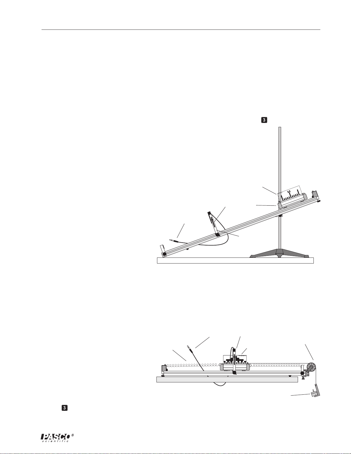
• Acceleration Down an Incline (Experiment 8):
Use a Photogate and the Smart T imer instead of a stop watch (Figure 5.1). Adjust the
height of the Photogate so the light path is intersected with the 5 cm fence of the Smart
Timer fences. Set up the Smart Timer to measure Acceleration, One Gate. Press
activate the Smart T imer, and
release the cart.
Smart Timer
Picket Fence
to
Smart Timer Picket Fence
• Simple Harmonic Oscillator
(Experiment 3):
Use a Photogate and the Smart
Timer instead of a stop watch, and
use the ME-9471 Picket Fence
(part number 648-04704) , not the
Smart Timer Picket Fence (Figure
6.1). Set up the Smart T imer to
measure Time, Pendulum. Press
to activate the Smart T imer to
measure the period of oscillation.
To Smart Timer
Figure 5.1
Setup for the
spring
Figure 6.1
Setup for the
Photogate
Head
Dynamics
Cart
Photogate
mounting
bracket
Acceleration Down an Incline
Photogate
To Smart Timer
Head
ME-9471
Picket Fence
Mass and Hanger
Simple Harmonic Oscillator
Experiment
Super Pulley
Experiment
31
Page 36

Smart Timer 012–06734A
• Oscillations on an Incline
(Experiment 4):
Use a photogate and the Smart
Timer instead of a stop watch, and
use the ME-9471 Picket Fence
(part number 648-04704), not the
ME-9471
Picket Fence
spring
Smart Timer Picket Fence (Figure
7.1). Set up the Smart Timer to
measure Time, Pendulum. Start
Photogate
Head
the cart oscillations, and Press
activate the Smart Timer to
measure the period of oscillation.
to Smart Timer
Photogate
Mounting
Bracket
Figure 7.1
Setup for the
Oscillations on an Incline
Experiment
• Springs in Series and Parallel (Experiment 5):
Use the setup illustrated in Figure 7.1. Set up the Smart T imer to measure Time,
Pendulum. Start the cart oscillations, and activate the Smart Timer to measure the
period of oscillation.
Note: The following experiment is in copy-ready form in the manual for the
Introductory Dynamics System with Computer Timing Kit (manual number
012-04894)
• Conservation of Energy (Experiment 8):
Use a Photogate and the Smart T imer instead of a computer and IDS Timer software, and
set the experiment up as directed in the experiment. Set up the Smart T imer to measure
Speed, One Gate. To measure the velocity of the cart, activate the Smart Timer and
before releasing the plunger of the Dynamics Cart.
32
Page 37

012–06734A Smart Timer
Note: The following experiment is in copy-ready form in the manuals for the
Mini Launcher (manual number 012-05479) and the Ballistic Pendulum/
Projectile Launcher (manual number 012-05375)
• Projectile Motion Using
Photogates ( Experiment 2):
Use the Smart T imer instead of a
computer and IDS T imer
software, and set the experiment
up as directed in the experiment.
Plug the photogates into the
Smart T imer as shown in Figure
8.1, and set up the Smart T imer
to measure Time, T wo Gates.
Press
to activate the Smart
Timer and fire the launcher.
Calculate the initial velocity
using the time required for the
ball to pass through the
photogates.
To Smart Timer
channel 1
ME-6825 Mini Launcher
(or ME-6800 Projectile
Launcher)
Figure 8.1
Setup for the
Projectile Motion Using Photogates
To Smart Timer
channel 2
Photogates
Photogate
Mounting
Bracket
Experiment
Note: The following experiment is in copy-ready form in the manual for the
Time of Flight Accessory (manual number 012-05088)
• Time of Flight and Initial
Velocity ( Experiment 1):
Use the Smart T imer instead of a
Photogate T imer, and set the
Smart T imer to measure Time,
T wo Gates. Be sure the plug
from the Photogate is connected
to channel 1 of the Smart Timer
and the plug from the T ime of
Flight Accessory is connected to
channel 2 (see Figure 9.1). Press
to activate the Smart T imer
and fire the launcher.
R
A
W
E
Y
T
E
F
A
S
–
S
E
S
S
A
L
G
M
E
-6
8
0
0
IN
N
W
E
.
H
U
E
S
Figure 9.1
Setup for the
Projectile
Launcher
IO
IO
C
C
U
U
A
A
T
T
N
N
!
!
D
D
O
O
N
N
L
L
O
O
T
T
O
O
O
O
K
K
D
D
O
O
W
W
N
N
B
B
A
A
!
!
R
R
R
R
L
L
E
E
S
H
O
R
T
R
A
N
G
E
PROJECTILE LAUNCHER
Photogate
Mounting Bracket
To Smart Timer
channel 1
Timer of Flight and Initial Velocity
To Smart Timer
channel 2
Time of Flight
Accessory
Experiment
33
Page 38

Smart Timer 012–06734A
• Determining the acceleration due
to gravity (g) with the
Free Fall Adapter (ME-9207B)
Insert the plug of the Free Fall
Adapter into channel 1 or 2 of the
Smart Timer (Figure 10.1) Set up
the Stopwatch mode of the Smart
Timer. Press
once. The Smart
Timer is now activated and will
record the time the interval
between the release of the ball and
the contact of the ball with the
receptor pad of the Free Fall
Adapter.
ball release
mechanism
controller box of the
Free Fall Adapter
steel ball
to Smart Timer
channel 1 or 2
support rod
and base
receptor pad
Figure 10.1
Setup for determining the acceleration due to gravity with the
ME-9207B Free Fall Adapter .
• Counting radiation with the
G-M Tube/Power Supply
(SN-7927)
Insert the plug of the G-M T ube/
Power Supply into channel 1 or 2
of the Smart Timer (Figure 11.1)
Set up the Smart T imer to
measure Counts, 30 seconds, 60
seconds, 5 minutes, or Manual.
Press
to activate the Smart
Timer.
34
To Smart Timer
channel 1 or 2
G-M Tube/
Power Supply
Figure 11.1
Setup for counting radiation with the SN-7927 G-M Tube/Power Supply
Page 39

012–06734A Smart Timer
T echnical Support
Feedback
If you have any comments about the product or manual,
please let us know. If you have any suggestions on
alternate experiments or find a problem in the manual,
please tell us. PASCO appreciates any customer
feedback. Your input helps us evaluate and improve our
product.
To Reach PASCO
For technical support, call us at 1-800-772-8700
(toll-free within the U.S.) or (916) 786-3800.
fax: (916) 786-3292
e-mail: techsupp@pasco.com
web: www.pasco.com
Contacting Technical Support
Before you call the PASCO Technical Support staff, it
would be helpful to prepare the following information:
➤ If your problem is with the PASCO apparatus, note:
- Title and model number (usually listed on the
label);
- Approximate age of apparatus;
- A detailed description of the problem/sequence of
events (in case you can’t call PASCO right away, you
won’t lose valuable data);
- If possible, have the apparatus within reach when
calling to facilitate description of individual parts.
➤ If your problem relates to the instruction manual,
note:
- Part number and revision (listed by month and year
on the front cover);
- Have the manual at hand to discuss your
questions.
35
Page 40

 Loading...