

Page 1
Instruction Sheet
for the PASCO
Model ME-8750
HARMONIC OSCILLATOR/DRIVER
012-05931A
1/96
$1.00
Introduction
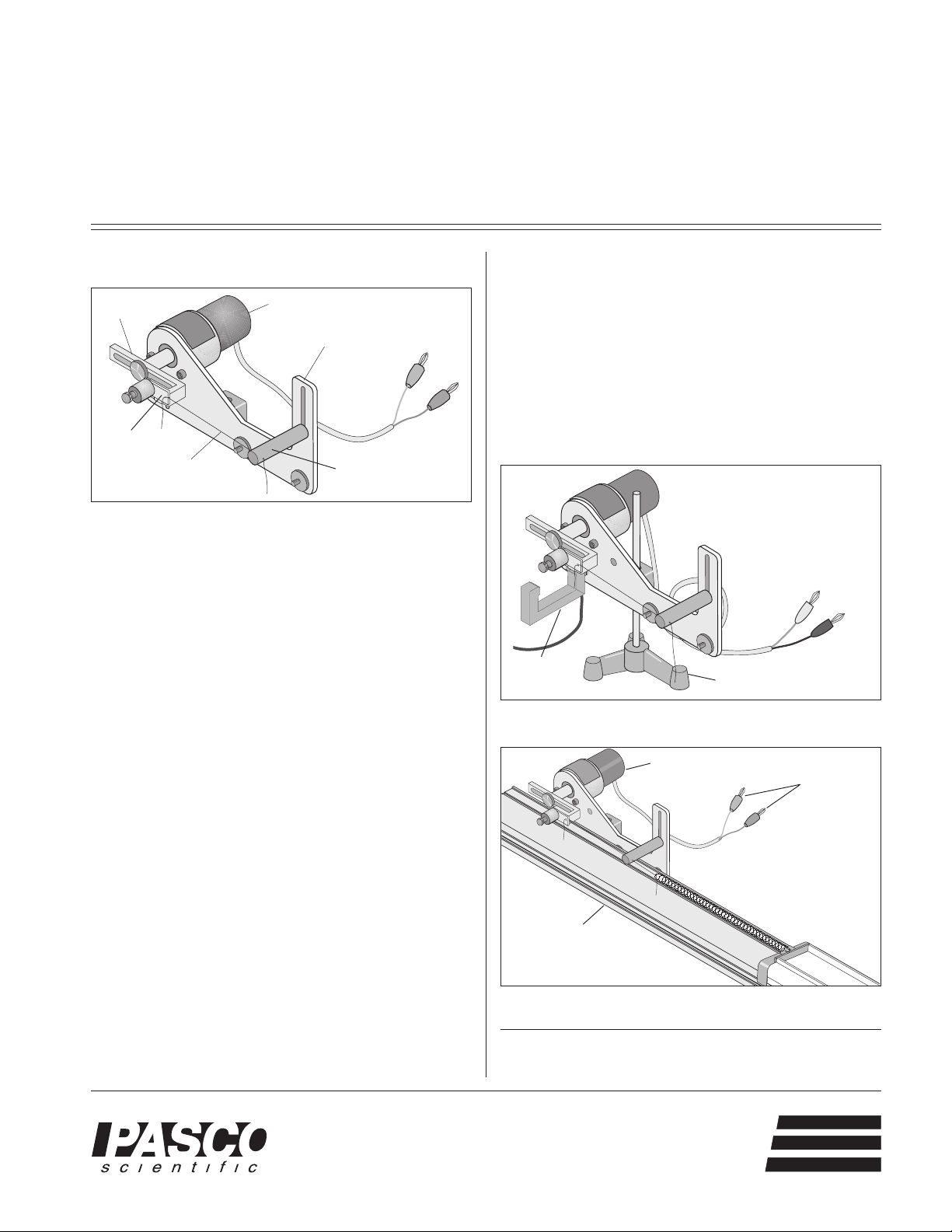
Offset
Driving Arm
String holder
String
The PASCO ME-8750 Harmonic Oscillator/Driver is designed to drive apparatus requiring a low frequency (0.3
to 3 Hz), high torque, sinusoidal oscillation. It consists of
a DC motor with an offset driving arm and a mounting
bracket. A string can be attached between the driving
arm and the apparatus which is to be driven. The Oscillator/Driver will provide a sinusoidal pull on the string. If
one desires to both push and pull on an apparatus, the
PASCO Push/Pull Accessory (ME-8751) may be added
to the Oscillator/Driver.
DC Motor
Mounting Bracket
String Guide
Equipment
Features
Operation of the Oscillator/Driver
➀ Mounting: The Oscillator/Driver can be mounted to a
dynamics track to drive dynamics carts or it can be
mounted on a rod stand for driving other apparatus.
See Figures 1 and 2. Tie one end of a string to the
white plastic piece on the driving arm and thread the
other end of the string through the hole in the guide.
The level of the guide can be adjusted by about 5.5 cm
to match the height of the object to be driven.
Harmonic
Oscillator/Driver
Power Source
Connectors
Photogate
Figure 1: Oscillator/Driver Mounted on a Rod Stand
Harmonic
Oscillator/Driver
Rod Stand
Power Source
Connectors
• 12 VDC motor (frequency: 0.3-3 Hz, current: 0-
0.3 A)
• Adjustable Amplitude: adjustable up to 12 cm.
• Photogate Attachment: A photogate can be attached to measure the frequency of the oscillator.
• Driver mounts on Dynamics Track or Rod Stand
• Rubber washers on mounting bracket provide quieter operation on the dynamics track.
• Optional Push/Pull Accessory (ME-8751):
Mounts to oscillator, replacing the string and allowing the apparatus to be pushed as well as
pulled.
®
10101 Foothills Blvd. • P.O. Box 619011 • Roseville, CA 95678-9011 USA
Phone (916) 786-3800 • FAX (916) 786-8905 • email: techsupp@PASCO.com
Dynamics
Track
Figure 2: Oscillator/Driver Mounted on Dynamics Track
© 1996 PASCO scientific
This instruction sheet written/edited by: Ann & Jon Hanks
better
ways to
teach science
Page 2
Harmonic Oscillator/Driver 012-05931A
➁ Amplitude Adjustment: To vary the amplitude,
loosen the thumb screw that holds the arm to the motor shaft and slide the arm to a new position. Retighten the thumb screw to hold the arm in place. The
amplitude is zero when the arm is positioned such that
the screw which holds the string holder is aligned over
the motor shaft.
➂ Power Supply: Plug the leads from the Oscillator/
Driver into a 12 V (0-0.3 A) variable DC power supply.
➤ NOTE: Do not exceed 12 V.
➃ Frequency Adjustment: To adjust the frequency,
change the voltage of the power supply. An increase
in the voltage corresponds to an increase in the frequency.
➄ Measuring the Frequency: Mount a photogate onto
the Oscillator/Driver using the slot located below the
motor. Each period, the arm will block the photogate.
See Figure 1.
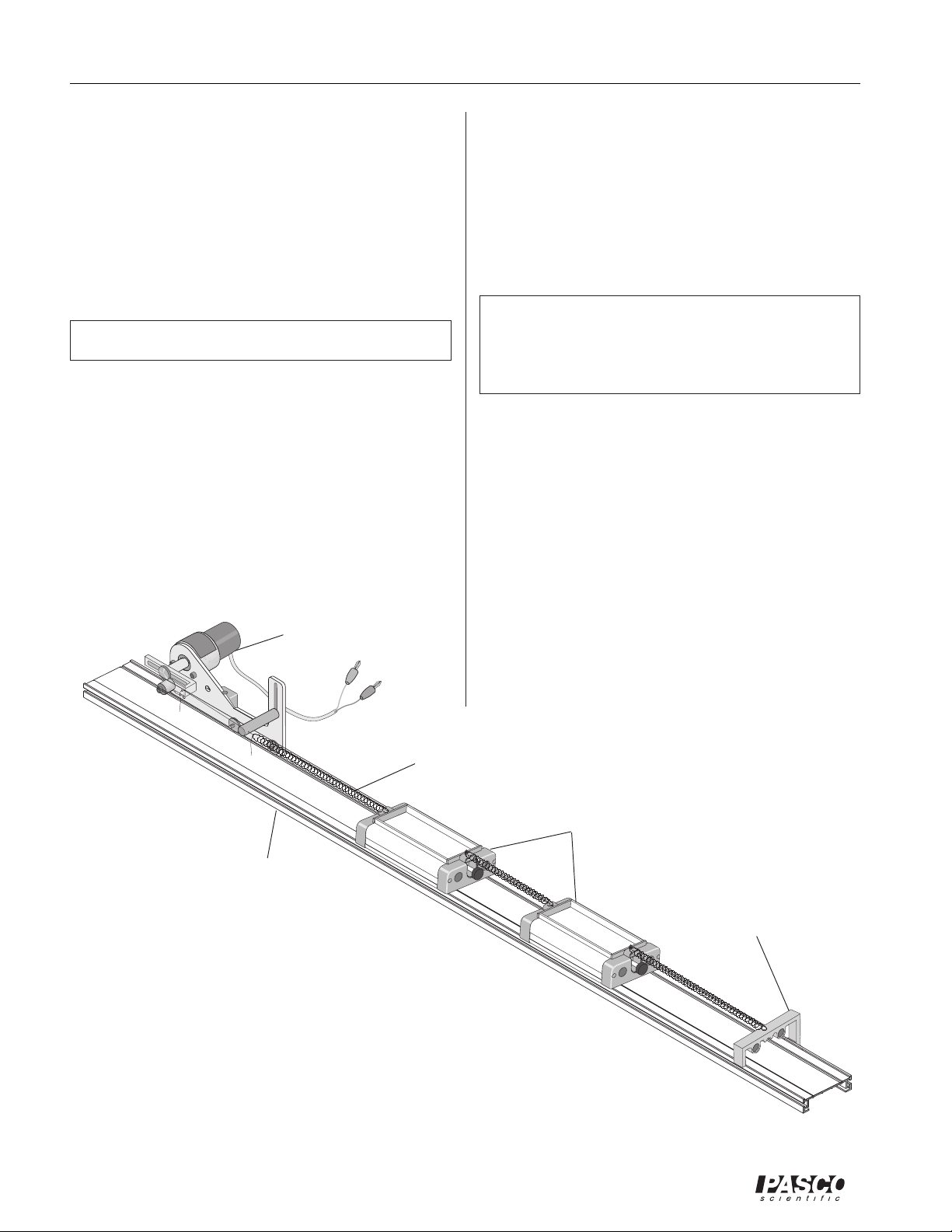
Harmonic
Oscillator/Driver
Suggested Uses for the Oscillator/Driver
➀ Attach a spring to each end of a dynamics cart. Con-
nect the free end of one spring to the adjustable end
stop at one end of the dynamics track. Connect the
free end of the second spring to a string tied to the
Oscillator/Driver and threaded through the string
guide. Drive the spring and cart system at various frequencies to find the resonant frequency of the system.
➤ NOTE: It generally takes the system a little
time to respond to a change in frequency of the
driving force so some patience is needed to see the
resulting change in amplitude.
➁ Use two carts and three springs to find the resonant
frequencies of the two different modes of oscillation.
See Figure 3.
Other Suggested Uses Requiring Additional
Push/Pull Accessory
➂ Mount the Oscillator/Driver on a rod stand and hang a
Longitudinal Wave Spring (WA-9401) from the hook
on the Push/Pull accessory. Create a transverse wave
in the spring to demonstrate that the wavelength varies
down the length of the hanging spring.
➃ Drive a set of hanging balls (see Figure 4) at various
frequencies to show different modes of oscillation and
chaotic motion.
Springs
Dynamics Carts
Dynamics Track
Figure 3: Resonant Modes of Oscillation of Carts and Springs
2
Adjustable
End Stop
®
Page 3

012-05931A Harmonic Oscillator/Driver
Limited Warranty
PASCO scientific warrants this product to be free from
defects in materials and workmanship for a period of one
year from the date of shipment to the customer. PASCO
will repair or replace, at its option, any part of the product
which is deemed to be defective in material or workmanship. This warranty does not cover damage to the product
caused by abuse or improper use. Determination of
whether a product failure is the result of a manufacturing
Harmonic
Oscillator/Driver
Push/Pull
Accessory
ME-8751
PUSH/PULL ACCESSORY
For use with ME-8750 Mechanical Oscillator Driver
Power Supply
defect or improper use by the customer shall be made
solely by PASCO scientific. Responsibility for the return
of equipment for warranty repair belongs to the customer.
Equipment must be properly packed to prevent damage
and shipped postage or freight prepaid. (Damage caused
by improper packing of the equipment for return shipment will not be covered by the warranty.) Shipping
costs for returning the equipment, after repair, will be
paid by PASCO scientific.
PASCO
MODEL SF-9582
PASCO
AC/DC POWER SUPPLY
scientific
67
5
4
3
2
VOLTAGE ADJUST
1
RESET
8
9
ON
10
11
12
OFF
AC OUTPUT
6 AMPS MAX
DC OUTPUT
6 AMPS MAX
Rod Stand
Colliding Balls
(not a PASCO product)
Figure 4: Resonant Modes of Oscillation and Chaotic Motion
®
3
Page 4

Harmonic Oscillator/Driver 012-05931A
T echnical Support
Feed-Back
If you have any comments about this product or this
manual please let us know. If you have any suggestions
on alternate experiments or find a problem in the manual
please tell us. PASCO appreciates any customer feedback. Your input helps us evaluate and improve our product.
To Reach PASCO
For Technical Support call us at 1-800-772-8700 (tollfree within the U.S.) or (916) 786-3800.
Internet: techsupp@PASCO.com
Tech Support Fax: (916)786-3292
Contacting Technical Support
Before you call the PASCO Technical Support staff it
would be helpful to prepare the following information:
• If your problem is computer/software related, note:
Title and Revision Date of software.
Type of Computer (Make, Model, Speed).
Type of external Cables/Peripherals.
• If your problem is with the PASCO apparatus, note:
Title and Model number (usually listed on the label).
Approximate age of apparatus.
A detailed description of the problem/sequence of
events. (In case you can't call PASCO right away, you
won't lose valuable data.)
If possible, have the apparatus within reach when calling. This makes descriptions of individual parts much
easier.
• If your problem relates to the instruction manual, note:
Part number and Revision (listed by month and year on
the front cover).
Have the manual at hand to discuss your questions.
4
®
 Loading...