

Page 1
Instruction Manual
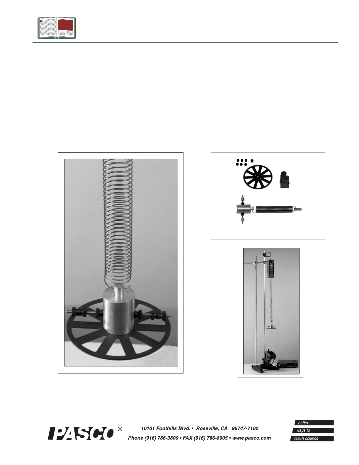
Wilberforce
Pendulum
Model No. ME-8091
Manual No. 012-08397A
Items Included
Page 2

Page 3

Pendulum Model No. ME-8091
Table of Contents
Equipment List........................................................ 3-4
Introduction ............................................................. 5
Setup Options ........................................................... 5
Equipment Setup ..................................................... 6-9
Suggested Experiment .............................................. 9-11
Sample Data/Results...................................................11
Troubleshooting ........................................................12
Appendix A: Specifications............................................ 13
Appendix B: Laser Safety Information ..........................14-15
Appendix C: DataStudio Setup Instructions for Wilberforce Pendulum
Experiments with
ScienceWorkshop
Interfaces ..................... 16
Appendix D: DataStudio Setup Instructions for Wilbeforce Pendulum
Experiments with PASPORT Interfaces .............................. 17
Appendix E: Technical Support ....................................... 18
Appendix F: Copyright and Warranty ................................ 18
2
®
Page 4
Model No. ME-8091 Wilberforce Pendulum
Wilberforce Pendulum
Model No. ME-8091
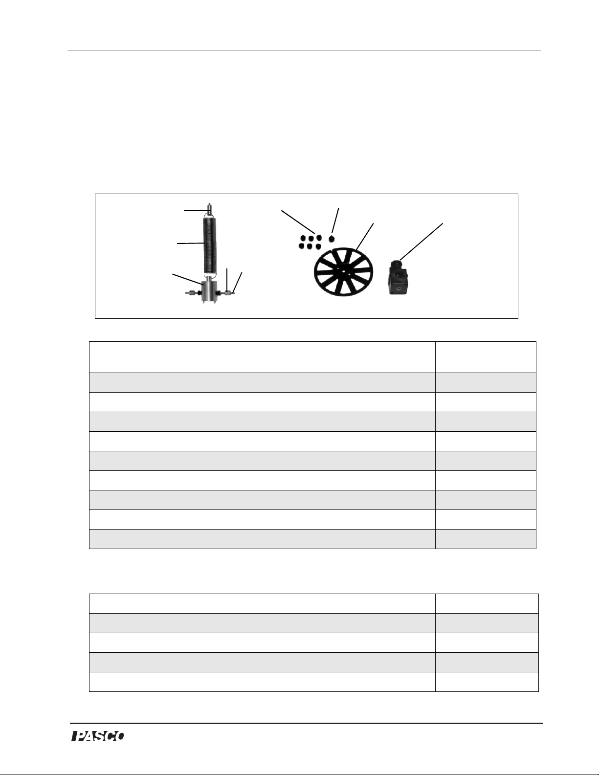
Equipment List
4
1
3
5
Included Equipment Replacement
1. Spring (1)
2. Threaded rod (1)
3. Brass Cylinder Mass, 0.9 cm diameter, 5.5 g (2)
4. Brass Cylinder Mount Holder, 0.9 cm diameter, 11 g (1)
5. Brass Cylinder Bob, 3.0 cm diameter, 234 g (1)
6. Photogate Wheel (1)
2
9
7
6
1
8
Model Number*
632-056
648-08341
615-231
648-08325
648-08324
648-08323
7. Thumbscrew for Photogate Wheel (1)
8. Rod Clamp (1)
9. Plastic masses (with thumbscrews), 0.5 g
616-141
003-05134
614-029
*Use Replacement Model Numbers to expedite replacement orders.
Additional Equipment Required (for setups with or without an interface) Model Number*
Large Rod Base (1)
Stainless Steel Rods (120 cm) (2)
Stainless Steel Rod (45 cm or 90 cm) (1)
Multi-Clamps (2)
®
ME-8735
ME-8741
ME-8736 or ME-8738
SE-9442
3
Page 5

Wilberforce Pendulum Model No. ME-8091
(Equipment Continued from Page 3)
Equipment Recommended (for setups with interfaces) Model Number*
A computer
Any PASCO data acquisition device (
PA SP O RT
™
interface, etc.)
ScienceWorkshop®
DataStudio Software
Force Sensor (1)
Motion Sensor (1)
Laser Switch (1)
X-Y Adjustable Diode Laser (1)
Adjustable Angle Clamp (1)
NA = not available for sale from PASCO scientific
interface,
NA
Various
CI-6870C
CI-6637 or PS-2104
CI-6688 or PS-2103
ME-9259A
OS-8526
ME-8744
4
®
Page 6

Model No. ME-8091 Wilberforce Pendulum
Introduction
The Wilberforce Pendulum allows students to investigate the
relationship between translational and torsional motion in an
oscillating pendulum. With force and motion sensors, a laser, laser
switch, and DataStudio software, students can collect real-time data of
the period, velocity, and acceleration of the pendulum’s oscillations.
Using the pendulum with the included Photogate Wheel, students can
observe the effect of rotational inertia on the oscillations. Brass
masses slide onto the crossbar of the pendulum bob, allowing students
to discover the affect of mass position on the period of oscillation. The
angular velocity, position, and acceleration during rotation can also be
plotted in a Graph display in DataStudio, enabling students to see a
visual display of the oscillatory periods and to isolate the point at
which the vertical and angular periods become equal.
WARNING: Before
setting up your equipment,
Setup Options
The Wilberforce Pendulum can be used with or without an interface
[either ScienceWorkshop interfaces or PASPORT interfaces (USB
Links etc),] and with various attachment pieces. With the spring and
attachments included, you can attach a Photogate Wheel for rotary
inertia experiments or use the brass mass to study the effect of mass on
the oscillatory period (Figures 1a and 1b).
please inform your
students of the hazards of
lasers and enforce
appropriate safety
precautions in your
classroom. For more
information, see Appendix
B: Laser Safety in this
manual.
Photogate
Plastic
Masses
Wheel
Cross
Bars
Figure 1a:
Setup with
Photogate
Wheel
Brass
Mass
Figure 1b:
Setup with
Brass
Masses
and Crossbars
Figure 1: Setup with ScienceWorkshop Interface and Sensors
®
Plastic
Mass
5
Page 7

Wilberforce Pendulum Model No. ME-8091
Equipment Setup
Equipment Setup (without an Interface or Sensors)
To mount the pendulum, perform steps 1-4 below. You will need a
stopwatch to record the period of the oscillations. Figure 2 below
shows the setup without an interface.
Equipment Setup (with an Interface and Sensors)
You will need a Rod Stand (ME-8735), three Stainless Steel Rods
(ME-8736 or 8738), two Multi-Clamps (SE-9442), one Adjustable
Angle Clamp (ME-8744), a Laser, and Laser Switch. (See the
Equipment lists on pages 3-4.)
1. Insert two 120 cm rods into the base of a rod stand. Keep the rods
upright in a vertical position.
2. Attach a Multi-Clamp to the
upper end of each rod (See
Figure 2). Slide a 45 (or 90
cm) steel rod through the hole
in the Multi-Clamps. Adjust
multi-clamps
rod clamp
mount
holder
the Multi-Clamps to hold the
rod horizontally in place.
3. Loop one end of a spring hook
through the hole on the top of
the brass cylinder bob. Loop
the hook on the other end of
the spring through the
cylindrical, brass mount
Figure 2: Standalone
Setup (without sensors)
holder.
(If using the pendulum without an interface, mount a rod clamp to the
horizontal rod, screw the brass mount holder (medium-sized
cylindrical brass mass) into the bottom hole of the rod clamp, and hook
the spring through the hole in the mount holder. See Figure 2.)
6
®
Page 8

Photogate Wheel
Model No. ME-8091 Wilberforce Pendulum
4. a) For setup with Photogate
Wheel: Use a thumbscrew
Plastic Masses
provided to attach the wheel to the
bottom of the large brass mass.
Screw two plastic masses onto
each side of the brass cylinder bob
(Figure 3). Add another plastic
mass to each side, allowing a gap
between the second mass and the
Figure 3: Setup with
Photogate Wheel
first mass. Finally, add a third
plastic mass to each side; the third mass is to hold the second mass
in place. (Note: When using the Photogate Wheel, do not put the
brass masses on the crossbar.)
OR
4b) For setup without the Photogate Wheel: Screw a small, plastic
mass over each side on the horizontal cross bar jutting from the large
brass mass. Screw on a brass mass on each side of the crossbar. Use a
measuring tape to ensure each brass mass is equidistant from the bob
in the center. Use two more plastic masses to hold the brass masses in
place (Figures 4a and 4b).
crossbar
equal distance
Figure 4a: Crossbar
with plastic masses
plastic
masses
plastic
mass
equal distance
Figure 4b: Brass
masses on crossbar
If using an interface, proceed with steps 5-12 that follow.
5. Use the center hole in the Force
Sensor to slide the Force Sensor
Laser
over the horizontal rod (Figure 5).
6. Insert the screw from the
cylindrical mount holder into the
bottom hole of the Force Sensor
Force Sensor
and rotate to tighten.
Figure 5: Force Sensor and
Laser Mounted on Rods
brass
mass
®
7
Page 9

Wilberforce Pendulum Model No. ME-8091
7. Mount an Adjustable Angle
Clamp to the lower end of the
base rod. Insert the Laser
Switch through the hole in the
rod clamp such that the Laser
clamp
Switch remains in a vertical
position and the opening
faces up (See Figure 6). Slide
the Motion Sensor over the
Laser Switch. Turn the
Adjustable Angle Clamp until
the laser switch holds
vertically in place. Do not
allow the Laser Switch room
to move, slip, or fall out of
place.
8. Plug the Motion Sensor into digital
channels 1 and 2 on the
ScienceWorkshop interface.
Motion
Sensor
Figure 6: Mounting the
Motion Sensor with Laser
laser switch
Laser
Diode
WARNING: Never look
directly at the laser light source (from
the Laser Diode) or reflected light
from the laser, such as from a mirror.
Although the lasers used in this
experiment are of low power, looking
directly into the laser light source or its
reflected light from a mirror could
cause severe eye injuries or burns. To
Laser
Switch
interface
avoid eye injury, do not look directly
into the beam of the laser and wear
laser protective eyewear. To align the
Laser Diode with the Laser Switch, use
an alignment marker (i.e ruler, piece of
Figure 7: Setup
tape, etc.) to check the alignment
before turning on the lasers. For more information about laser safety,
see Appendix B of this manual.
9. Align the Laser Diode vertical over the opening on the laser switch.
Use the adjustment knobs on the Laser Diode to move the laser
horizontally.
8
®
Page 10

Model No. ME-8091 Wilberforce Pendulum
10. Plug from the Laser Switch to digital channel 3 on the
ScienceWorkshop interface. For a picture of the complete setup,
see Figure 7.
11. Follow the DataStudio setup instructions in Appendices C
(ScienceWorkshop interfaces) and D (PASPORT interfaces.)
12. When you are ready to collect data, plug the Laser Diode into a
wall outlet. (Note: As a safety precaution, unplug the Laser Diode
and Laser Switch until just before you are ready to begin data
collection.)
Suggested Experiment: Investigating
Translational and Torsional Motion in a
Pendulum
This experiment has two parts: In Part I, you will investigate the
relationship between translational and torsional oscillatory motion in a
pendulum with a brass mass hanging from a spring. In Part II, you will
examine the effect of the inertia from a Photogate Wheel on a
pendulum.
Note: When using the Photogate Wheel, use the plastic masses instead
of the brass masses on the crossbar. If you attach the disk, you must
use the plastic, black masses on the crossbar because the brass masses
have too much rotational inertia. To change the period of the
pendulum’s oscillations, change the distance of the masses from the
center.
Part I: Effect of Mass on Oscillatory Periods in a Pendulum
1. Follow the equipment setup procedure described on pages 5-6 of this
manual.
2. Move the position of the masses on the crossbar until they are
equidistant from the centermost point on the pendulum bob.
3. Record the weight of the brass masses in Table 1. (Note: If a mass
balance is not available, see the Specifications section in Appendix
A.)
4. With a metric measuring tape, measure the distance of each mass
from the center point on the bob. Record your measurement in
Table 1.
®
9
Page 11

Wilberforce Pendulum Model No. ME-8091
5. Pull on the bob to begin moving the pendulum in a vertical
direction. The crossbar will rotate as the pendulum bobs up and
down.
6. In DataStudio, click the Start button to begin collecting data.
Observe the data in real-time as the pendulum oscillates. (If using
the pendulum without a computer and interface, use a stopwatch to
time both the vertical and rotational periods of the oscillations and
the time when the periods become equal.)
7. Move the masses on the crossbar to a new position and repeat steps
4 through 6. (Encourage students to move the masses on the
crossbar to various positions to see the affect that mass position has
on the period and angular velocity. Have students adjust the
masses until the periods of the vertical and rotational oscillations
are the same.)
Note: The periods of the vertical and rotational oscillations must be
exactly the same (quantitatively equal) for the oscillations to switch
completely between the vertical and rotational modes. If the periods
are not equal, adjust the masses on the crossbar and pull the pendulum
again. This may take a few runs of trial and error.)
Table 1: Oscillatory Periods with Varying Mass on a Pendulum Bob
Run
No.
1 vertical:
Distance of
Mass from
Pendulum
Bob (cm)
Oscillatory
Period
(seconds)
rotational:
*
Maximum
Angular
Velocity
(rad/s)
Maximum
Force
(N/m)
Tip: If the masses on the
crossbar are not equidistant from the center, the
crossbar will not spin
smoothly.
2 vertical:
rotational:
3 vertical:
rotational:
4 vertical:
rotational:
5 vertical:
rotational:
*To measure the period in DataStudio, use the Smart Tool to measure
the difference between wave crests or troughs.
10
®
Page 12

Model No. ME-8091 Wilberforce Pendulum
Part II: The Effect of Rotational Inertia on Oscillatory Periods
from a Pendulum Swing
Table 2: The Effect of Rotational Inertia on a Pendulum’s Oscillation
Run
No.
1 vertical:
2 vertical:
3 vertical:
4 vertical:
5 vertical:
Disk
Radius
(cm)
Rotational
Inertia
2
(kg/m
)
Oscillation
Period
(seconds)
rotational:
rotational:
rotational:
rotational:
rotational:
Sample Data/Results
Maximum
Angular
Velocity
(rad/s)
Maximum
Force
(N/m)
®
11
Page 13

Wilberforce Pendulum Model No. ME-8091
Troubleshooting
Problem(s) Possible Reason(s) Possible Solution(s)
No position reading appears
in DataStudio.
The period for the torsional
and vertical motions are not
the same.
Force reading is negative. Improper calibration or direction
Rotational data does not
appear in software during
data collection.
Motion Sensor is not plugged
into the interface.
Masses are unequal distances
from the center of the crossbar.
of force measurement is not
defined in DataStudio.
a) The Laser Switch is not
plugged into an interface. b)
Laser Diode is not turned on. c)
Laser Switch and Diode are not
vertically aligned. d) Smart
Pulley option was not selected
in the DataStudio Setup window
(applies to
interfaces).
e) Timing sequence for the
laser switch is not defined in
DataStudio (applies to
PASPORT interfaces).
ScienceWorkshop
Plug the digital channels of the
Motion Sensor into the
interface.
Move the masses on the cross
bar. Moving the masses out
increases the period. Keep
adjusting the distance of the
masses until the periods are
the same.
Calibrate the Force Sensor both
at zero and with a known mass.
Follow the calibration
instructions in the Force Sensor
Manual or the DataStudio
online help. If using a
PASPORT Force Sensor, open
the Setup window, scroll to the
Force Sensor, and select the
“Pull Positive” option.
a) Plug the Laser Switch into a
digital channel on the interface.
b) Plug the Laser Diode into a
power outlet. c) Adjust the
beam position on the Laser
Diode until it aligns with the
Laser Switch. d) In the Sensors
list of the Experiment Setup
window, select the Smart Pulley
option.
e) In DataStudio, define a
timing sequence for the laser
switch. (See the table of
contents in the online help for
defining timing sequences with
photogates and other timers.)
12
®
Page 14

Model No. ME-8091 Wilberforce Pendulum
Appendix A: Specifications
Wilberforce Pendulum
Components
Springs 10.2 cm length, 48.5 g
Brass Cylinder Bob 234.0 g, 3.0 cm (diameter) x 1.0 cm
length
Brass Cylinder Mount 11.0 g, 0.9 cm (diameter) x 1.9 cm
(length)
Brass Cylindrical Masses
Photogate Wheel 10 cm diameter, 7.5 g, 31.4 cm
Plastic Masses 0.5 g
Crossbar 6.0 g, 10 cm length
5.5 g, 0.9 cm (diameter) x 3.7 cm
(length)
circumference
®
13
Page 15

Wilberforce Pendulum Model No. ME-8091
Appendix B: Laser Safety Information
The OS-8528 Diode is a low power, Class I laser. When Class I lasers
are used in accordance with Occupational Health and Safety
Administration (OSHA) standards, Class I lasers are not harmful.
PASCO cannot be held liable for negligent use in the classroom. As a
courtesy, we are providing you with the following laser safety
instructions. These reminders are not a comprehensive list of all
possible safety measures or hazards. For more information, see the
OSHA web site (http://www.osha.gov). Also see http://
www.safetymanual.com or www.laserinstitute.org
Safety Reminders:
• Never look directly into the laser.
Laser Diode
laser beam
WARNING:
DO NOT LOOK
DIRECTLY UP
OR DOWN INTO
THE BEAM.
Laser Switch
Figure 5a: Harmful ways to look at a laser beam
• Do not point a laser at your own eye or at the eyes of other
individuals.
14
®
Page 16

Model No. ME-8091 Wilberforce Pendulum
• Never remove any of the covering or components of the AP-8586
Diode Laser. If the laser is defective, return the defective laser
immediately to PASCO scientific.
• Although laser protective eyewear is not typically required for class I
lasers, if you are uncomfortable or unsure about working around
lasers, wear protective laser goggles or spectacles.
About Laser Protective Eyewear
The eyewear must be designed for use with lasers and meet OSHA
standards specific to the type and class of laser you are using. You can
tell if the type of goggle or spectacle you are using meets laser
standards by looking at the insignia on the side of the frame. Any type
of plastic chemical protective goggle will not suffice. Also, you need
to select protective eyewear with the correct filter for the wavelength
range of the laser (For the Laser Diode, you need a 660-680 nm filter.)
Example: Laser goggles designed to protect for Class I lasers do not
provide maximum protection when using Class II lasers. For more
information, see the OSHA web site (www.osha.gov).
®
15
Page 17

Wilberforce Pendulum Model No. ME-8091
Appendix C: DataStudio Setup Instructions for
Wilberforce Pendulum Experiments with
ScienceWorkshop
Interfaces
1. Connect the sensors to the ScienceWorkshop interface, as follows:
a) Plug the stereo plugs on the Motion Sensor to digital channels 1
and 2 on the interface. b) Plug the DIN connector on the Force
Sensor to any analog channel on the interface. c) Plug the stereo
plug of the Laser Switch into digital channel 3 on the
ScienceWorkshop interface.
2. Open DataStudio and select “Create Experiment.”
3. Click the Setup button to open the Experiment Setup window.
4. In the Sensors list, drag the Motion Sensor icon to the first two
digital channels on the picture of the interface. Drag the Force
Sensor to the same channel you have the sensor plugged into on
the picture of the interface.
5. Select the Smart Pulley from the Sensors list and drag it to the third
digital channel on the interface. [For the Laser Switch, you will use
the Smart Pulley icon (instead of the Laser Switch icon) in the
Setup window. If you use the Laser Switch icon, you need to set up
a timing scheme in DataStudio.]
6. Double click on the Smart Pulley icon to open the Sensor Properties
dialog. In the Measurement tab, click to check the Angular
Position (rad), Angular Velocity (rad/s), and Angular Acceleration
(rad/s/s) options.
7. Your experiment is setup in DataStudio. On the main toolbar, click
the Start button to begin recording data. You will obtain six
graphs: position vs. time, velocity vs. time, force vs. time, angular
position vs. time, angular velocity vs. time, and angular
acceleration vs. time.
Note: If you do not see the
Sensor list, click the Setup
button on the main toolbar. In the Experiment
Setup window, click the
Change button. In the
“Please Choose Data
Source” window, select
the appropriate interface
and click the OK button.
Note: Calibration of the
Force Sensor is optional.
However, if you wish to
calibrate, click on the Calibration tab and follow the
“General Procedure for
Calibrating Sensors” in
the DataStudio online
help. You will need a set
of known masses for calibrating the Force Sensor.
16
®
Page 18

Model No. ME-8091 Wilberforce Pendulum
Appendix D: DataStudio Setup Instructions for
Wilberforce Pendulum Experiments with
PASPORT
1. Connect two USB links (or other PASPORT interfaces) to a USB port
(or USB hub) on your computer.
Interfaces
2. Plug the Motion Sensor and Force Sensor each to a USB Link or
other PASPORT interface.
3. Plug the Laser Switch into either port on a PASPORT Photogate
Port (PS-2123).
4. Click the Setup button to open the Experiment Setup window.
5. In the Experiment Setup window, scroll to the Force Sensor options
and select “Force, pull positive.” Scroll to the Motion Sensor and
click (to check) the boxes next to “Velocity.”
6. In the PASPORT Setup window, click the Add Timer button,
select Recordable Timer from the Choose Timer window, and
click OK. You will use a custom timing sequence to record each
time the rotation disk passes the beam of the laser.
7. In the Setup window, scroll to and doubleclick the Recordable
Timer option. When you are ready to begin collecting data, click
the Record Sequence button. Blocked and unblocked events will
appear in the open display.
8. You will obtain six graphs: position vs. time, velocity vs. time, and
force vs. time, angular position vs. time, angular velocity vs. time,
and angular acceleration vs. time.
Note: If you do not see the
Sensor list, click the Setup
button on the main toolbar. To view the entire list
of sensors, click the Maximize button in the upper
right-hand corner of the
screen.
Note: Calibration of the
Force Sensor is optional.
However, if you wish to
calibrate, ”General Procedure for Calibrating
Sensors” in the DataStudio online help. You will
need a set of known
masses for calibrating the
Force Sensor.
®
17
Page 19

Wilberforce Pendulum Model No. ME-8091
Appendix E: Technical Support
For assistance with the ME-8091 Wilberforce Pendulum or any other PASCO products,
contact PASCO as follows:
Address: PASCO scientific
10101 Foothills Blvd.
Roseville, CA 95747-7100
Phone: (916) 786-3800
FAX: (916) 786-3292
Web: www.pasco.com
Email: techsupp@pasco.com
Appendix F: Copyright and Warranty Information
Copyright Notice
The PASCO scientific 012-08397A Wilberforce Pendulum Manual is copyrighted and all
rights reserved. However, permission is granted to non-profit educational institutions for
reproduction of any part of the 012-08397A Wilberforce Pendulum Manual, providing the
reproductions are used only for their laboratories and are not sold for profit. Reproduction
under any other circumstances, without the written consent of PASCO scientific, is
prohibited.
Limited Warranty
PASCO scientific warrants the product to be free from defects in materials and workmanship
for a period of one year from the date of shipment to the customer. PASCO will repair or
replace, at its option, any part of the product which is deemed to be defective in material or
workmanship. The warranty does not cover damage to the product caused by abuse or
improper use. Determination of whether a product failure is the result of a manufacturing
defect or improper use by the customer shall be made solely by PASCO scientific.
Responsibility for the return of equipment for warranty repair belongs to the customer.
Equipment must be properly packed to prevent damage and shipped postage or freight
prepaid. (Damage caused by improper packing of the equipment for return shipment will not
be covered by the warranty.) Shipping costs for returning the equipment after repair will be
paid by PASCO scientific.
18
®
Page 20

 Loading...