

Page 1
Instruction Manual
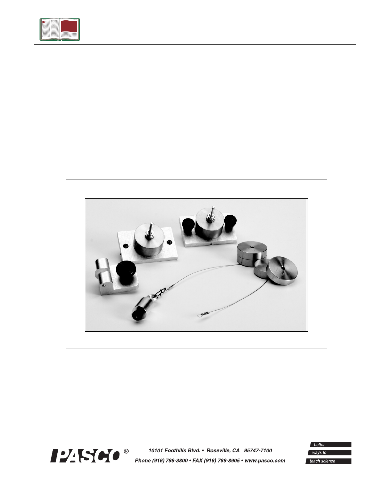
Computer-Based
Centripetal Force
Accessory
Model No. ME-8089
Manual No. 012-08425A
Page 2

Centripetal Force Accessory Model No. ME-8089
Table of Contents
Equipment List........................................................... 3
Introduction ............................................................. 4
Equipment Setup ..................................................... 4-7
Suggested Experiment .............................................. 7-10
Part I: Centripetal Force vs. Velocity......................................................................................... 7-9
Part II: Centripetal Force vs. Mass.................................................................................................9
Part III: Centripetal Force vs. Radius...........................................................................................10
Sample Data/Results...................................................10
Appendix A: DataStudio Setup Instructions ...................... 11
Appendix B: Technical Support ....................................... 12
Appendix C: Copyright and Warranty Information .................. 12
2
®
Page 3
Model No. ME-8089 Centripetal Force Accessory
Computer-Based
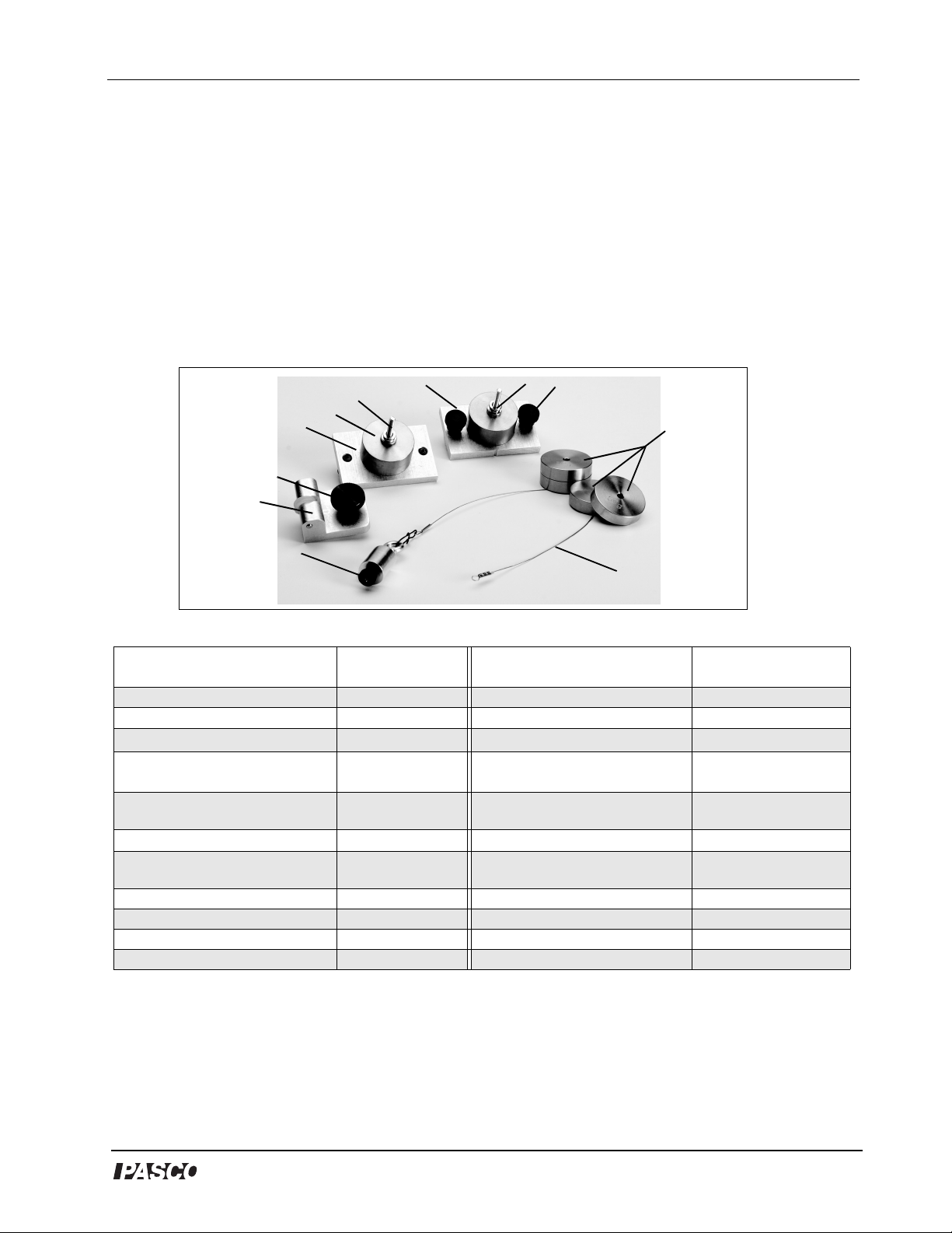
Centripetal Force Accessory
Model No. ME-8089
Equipment List
9
7
6
5
4
3
8
10
11
2
1
Included Equipment Model
Number
1. Connecting Cable (1) 623-038 Rotating Platform ME-8951
2. Ball Bearing Swivel, 12.5 g (1) 648-08386 A computer N/A
3. Pivot block (1) 648-08422
4. Thumbscrew for Pivot Block
(1)
5. Sliding Mass Holder (1) 648-08423
6. Mass, 100 g (2) 648-06511
7. Screws for Mass Holders (2) 610-246 Steel Rod (45 and 90 cm or 120
8. Stationary Mass Holder (1) 648-08424 Multi-Clamp SE-9442
9. Nuts for Mass Holders (2) 614-006 Large Rod Base (2) ME-8735
10. Thumbscrews (2) 613-067 Experiment Setup Disk 013-08425A
11. Mass, 50 g (4) 648-06510
*PASPORT™ sensors (with PS-prefix) require a PASPORT™ interface PS-2100(2) or PS-2001(1) for operation. A Photogate
Port (PS-2123) is required for photogate use with PASPORT interfaces.
**ScienceWorkshop
Optional equipment: For constant speed studies, a Motor Drive (ME-8955) with DC Power Supply (SF-9584A) is
recommended.
®
sensors (with CI-prefix) require a ScienceWorkshop® interface for operation.
617-003
Additional Equipment
Required
DataStudio® Software
Computer Interface
Force Sensor
Photogate Head/Port ME-9498A, PS-2123
cm)
PASPORT* or
Model
Number
See PASCO catalog.
ScienceWorkshop
PS-2104* or
CI-6746**
ME-8736/ME-8738/
ME-8741
**
*
®
3
Page 4

Centripetal Force Accessory Model No. ME-8089
Introduction
PASCO’s Computer-Based Centripetal Force Accessory
(ME-8089) allows students to investigate the relationships
between centripetal force, radius, mass, and velocity for
an object undergoing uniform circular motion. Traditional
experiments in this area involve the swinging of masses
above the head. The traditional approach is difficult to
execute and data is rarely sufficient for an understanding
of the relationships. With a computer interface, Force
Sensor, and photogate, the Computer-Based Centripetal
Force Accessory removes these difficulties by allowing
the student to directly measure and observe the force and
velocity of the mass as it rotates.
Masses are included with the apparatus to facilitate a
range of mass trials. The sliding and stationary mass holders provided with the accessory attach to a PASCO Rotating Platform (ME-8951). Spinning the Rotating Platform
and allowing it to slow down (without assistance) varies
the velocity. The platform can be manually spun by hand
or automatically with a Motor Drive (ME-8955) and DC power supply. Sliding the captured
masses along the grooves in the rotating platform changes the radius. For radius measurements, a
convenient measuring scale is included on the top edge of the platform.
Figure 1: Setup with Force
Sensor on Stand
Equipment Setup
1. Insert the photogate post into the base
stand and into the photogate head.
2. Use a thumbscrew to mount a Photogate
Head (ME-9498A) to the bottom of the
“A” base (See Figure 2). Let the Photogate
Head rest over the first ring on the 3-step
pulley of the Rotating Platform. (Note:
Ensure that the positioning of the
photogate does not restrict movement of
the shaft).
3. Connect the photogate to a computer
interface (ScienceWorkshop or
PAS PO RT ).
4
photogate
pulley
steel rod
cable
to interface
Figure 2: Photogate on Base
of Centripetal Apparatus
®
Page 5

Model No. ME-8089 Centripetal Force Accessory
Note: If using a PASPORT interface, connect the photogate to a PASPORT Photogate Port.
4. Slide the pivot block through the groove to the center of the platform. (Note: The indent
mark on the pivot block must face the zero position on the measuring tape.) Tighten in
place.
5. Slide the fixed mass holder onto the platform. Slide the nuts into the T-slot and tighten the
thumbscrews over the nuts.
6. Insert the sliding mass holder through the groove on the top of the platform, such that the
side indent faces the measuring tape.
7. Mount a 90 cm stainless steel rod vertically into a second “A” base stand.
8. Attach a Multi-Clamp to the upper end of the stainless steel rod (See Figure 3a).
9. Insert the shorter stainless steel rod (45 cm) horizontally into the Multi-Clamp.
Note: With an additional rod and clamp, you can insert another rod into the base stand and a
longer crossbar(rod) into the clamp. This creates a more stable structure.
10. Slide a Force Sensor onto the stainless steel rod and adjust the top screw to anchor it to the
rod (Figure 3a). (Note: Be sure to keep the cords from the sensor out of the path of the
rotating arm.)
11. Attach the ball bearing swivel to the bottom of the Force Sensor.
Force
clamp
Figure 3a: Mounting the Force Sensor
Sensor
swivel
cable
pivot block
cable
pulley
Figure 3b: Threading the cable through
the sliding mass holder
sliding mass
holder
12. Thread the cable from the swivel hook through the pulley and over the screw of the
“sliding mass” holder (Figure 3b).
13. Move the Force sensor directly over the pivot block in the center of the platform. (Note:
You can adjust the radius of the sliding mass holder by moving the crossbar higher or
lower.)
®
5
Page 6

Centripetal Force Accessory Model No. ME-8089
Note: Always lay down the cable before adding the mass.
14. Add a mass over the cable on the sliding mass holder; then tightly
screw on the knurled nut to hold the mass in place (Figure 4).
15. Add a mass to the fixed mass holder and use a knurled nut to hold
the mass in place. (WARNING: Keep the thumbscrews tight or
the mass holder will slide off during the rotation.).
Fixed Mass Holder
Figure 4: Mass Holders
Sliding Mass Holder
16. Move both the fixed and sliding mass holders the same distance
from the center on the platform (You can choose any arbitrary
radius).
17. Plug the Force Sensor into a a
PASPORT or ScienceWorkshop
computer interface.
CAUTION: Keep all cords away
from the rotating arm. The rotating
arm must be free to move 360
degrees without hitting any objects
Force
Sensor
to interface
in its path.
Note: To calibrate the
ScienceWorkshop Force
Sensor, follow the
instructions provided in
the documentation
included with your
Force Sensor or in the
DataStudio online help.
Calibration of the
PASPORT Force Sensor
is not required.
However, you can tare
the PASPORT Force
Sensor by pressing the
Zero button without any
weight attached.
Note: PAS C O’s PASP ORT
Force Sensor (PS-2104)
requires a PASPORT
interface; PASCO’s
ScienceWorkshop Force
Sensor (CI-6746) requires
a ScienceWorkshop
interface.
WARNING: Do not stand
next to rotating arm or look at the
rotating arm at eye level. To avoid
possible injury from the rotating
arm hitting the body, keep at least 1
foot distance from the rotating arm.
Figure 5: Complete Setup
for Experiments
18. Open the appropriate DataStudio file on the experiment setup disk.
19. Launch DataStudio and click the Start button to begin collecting data.
6
Note: DataStudio setup
instructions (for either
PASPORT or ScienceWorkshop sensors) are
available in Appendix A.
®
Page 7

Model No. ME-8089 Centripetal Force Accessory
Attaching a Motor Drive with Power Supply (Optional)
If you plan to do a constant speed experiment, you may want to consider purchasing a motor
drive. A motor drive requires a DC power supply of function generator for operation. The
instructions for mounting the drive are included with the apparatus. Figure 6 shows a picture
of a motor drive attached to the 3-step pulley.
3-step pulley
Figure 6: Motor
Drive attached to
a 3-step pulley
drive belt
motor
to power supply
PASCO’s Motor Drive (ME-8955) comes with a drive belt for connecting the motor drive to
the pulley.
Suggested Experiment: Centripetal Force and Velocity
Equipment Required
Rotating Platform (ME-8951) Computer interface (
PASPORT
Force Sensor (PS-2104* or CI-6746**) DataStudio Software (ver. 1.5 or higher)
Photogate Head (ME-9498A) and/or Photogate
Port (PS-2123)*
Base support, clamps, and mounting rods
ScienceWorkshop
or
*PASPORT sensors (with PS-prefix) require a PASPORT interface [PS-2100(2) or PS-2001(1)] for operation. A Photogate Port
(PS-2123) is required for photogate use with PASPORT interfaces.
**ScienceWorkshop sensors (with CI-prefix) require a ScienceWorkshop interface (CI-6400 or CI-6450 or CI-7450) for
operation.
Optional: For constant speed studies, a Motor Drive (ME-8955) with a DC power supply (SF-9584A) is recommended.
Part I: Centripetal Force vs. Velocity
In Part I of this experiment, you will vary the velocity by spinning the platform to a high, safe
velocity. The velocity decreases over time as the centripetal force is continuously measured
by the Force Sensor. The radius and mass are held constant as the velocity decreases.
®
7
Page 8

Centripetal Force Accessory Model No. ME-8089
Setup
Follow the equipment setup instructions on pages
4-7 of this manual. Use the appropriate
DataStudio setup file on the experiment disk or
the DataStudio setup instructions in Appendix A.
Experiment Tips
a)To add mass to the “sliding mass” holder, lay
the components over the attachment screw in
the following order: a) cable b) mass and c) nut
Figure 1-1: Spinning the Platform
to tighten.
Note: Do not place the mass underneath the
cable, as this will interfere with a proper measurement.
b) Place an equal amount of mass on the “fixed mass” and “sliding mass” holders.
c) Be sure to place the “fixed mass” at the same radius as the “sliding mass” to ensure
balancing of the unit as it rotates.
d) To add the “sliding mass,” lay the components over the attachment screw in the following
order: a) cable b) mass and c) nut and d) thumbscrews to tighten.
e) The velocity of the “sliding mass” can be measured as an angular velocity. In DataStudio,
use a Graph display to monitor the velocity of the rotating mass. If velocity readings do
not appear, check your photogate connection and DataStudio setup (See Appendix A).
f) To vary the radius, adjust the position of the Force Sensor (See Figure 1-3.)
g) If the rotating arm does not move, there may be too much friction in the cable or the pulley
and turning rod may be too tight. Move the Force Sensor down to loosen the cable or
adjust the turning rod.
Experiment Procedure
1. Place 100 g mass on each mass holder and secure with the thumbscrews.
2. Adjust the position of the fixed and sliding mass to about 20 cm (Note: The maximum
radius is 22 cm. To adjust the position, pull outward on the mass to tighten the wire.)
3. Set up your experiment in DataStudio. Set the smart pulley on angular speed (rad/sec) and
create two equations: Force= -smooth (10, F) and speed squared=V^2. Set the sample rate
to 10 Hz. (For more information, see Appendix A.)
4. With the knurled shaft, spin the rotating platform (by hand) to about 6 radians/second (1 or
2 Hz) and let go.
8
®
Page 9

Model No. ME-8089 Centripetal Force Accessory
5. In DataStudio, click the Start button and watch the Force vs. Speed graph as the platform
speed decreases. When the speed falls below 2 radians/second, click the Stop button.
Analysis:
1. Explain the shape of the force vs. velocity graph.
2. Create a graph of Force vs. Speed Squared. Does the graph show a straight line? Why or
why not? Find the slope.
3. Calculate the theoretical slope for where the slope is mr. Calculate the slope
F mr
=
2
ω
using your values of m and r. Calculate the percent (%) difference between the two
values.
Part II: Centripetal Force vs. Mass
In Part II, the radius and velocity are held constant as the mass is varied. Adding extra drilled
masses to the mass holder increases the mass of the system. Equal amounts of mass must
also be added to the “fixed mass” to balance the arm as it rotates. Centripetal force is directly
measured by the Force Sensor.
“Fixed” Mass
Holder
Rotating
Arm
Figure 1-2A: Free and Fixed
Mass Holders
“Sliding” Mass
Holder
Figure 1-2B: Adding mass
to a holder
Perform several different data runs, each time varying the mass on the sliding and fixed mass
holders. (The mass holder is about 50 g. The mass can be varied from 50 to 250 g in 50 g
increments.) (Note: Keep the speed constant. A motor drive with power supply can be used
to ensure a constant speed. Otherwise, spin the platform with your hand above some set speed
and start recording. When the platform slows down below the set speed, stop recording.)
Use a graph or table to record the force at a set speed. Repeat the experiment for the other
masses and make an editable graph of the Force vs. Mass.
®
9
Page 10

Centripetal Force Accessory Model No. ME-8089
Part III: Centripetal Force vs. Radius
In Part III, the velocity and mass are held
constant as the radius is varied. Lowering the
Force Sensor increases the radius. As the radius
increases, the “fixed mass” must be moved to a
matching radius to balance the rotating arm.
Again, centripetal force is measured by the Force
Sensor. Repeat the experiment at different radii
(i.e.vary the radius from 22 cm to 8 cm in 2 cm
steps). Use a graph or table to record the force at
the set speed. In DataStudio, make an editable
graph of the Force vs. Radius.
Figure 1-3: Changing the Radius
Note: If force readings do not appear in
DataStudio, check your sensor-to-interface
connections and setup in DataStudio. See Appendix A of this manual.
Sample Data/Results (for Part I)
10
®
Page 11

Model No. ME-8089 Centripetal Force Accessory
Appendix A: DataStudio Setup Instructions
An experiment setup disk is included (with the ME-8089) for setting up the experiments in
this manual. The setup disk also contains DataStudio files for experiments involving linear
velocity. (The instructions below are for those wishing to create the DataStudio setup files.)
Procedure Steps
PART I: Plug the
sensors into the
interface:
PART II: Set up your
experiment
PART III: Create your
equations
PART IV: Collect Data a) Open a display and click the Start button on the main toolbar.
PASPORT: a) Plug the Photogate into either channel 1 or 2 on a PASPORT
Photogate Port. b) Plug both the Photogate Port and Force Sensor into a
PASPORT interface (i.e. USB Link, Xplorer, PowerLink, etc.).
OR
ScienceWorkshop: a) Plug the Photogate into a digital channel on the
ScienceWorkshop
(A, B, or C) on the
PASPORT: a) Open DataStudio and select “Create Experiment.” b) On the main
toolbar, click the Setup button to open the Experiment Setup window. c) When the
Experiment Setup dialog opens, click on the Add Timer button, select the Smart
Pulley (Rotational) icon, accept the default spoke angle spacing, and click OK.
d) In the Setup window, scroll to the Force Sensor and select “pull, positive.” Keep
the sample rate at 10 Hz.
OR
ScienceWorkshop: a) Open DataStudio and select “Create Experiment.” b) On
the main toolbar, click the Setup button to open the Experiment Setup window.
c) In the Sensors list of the Experiment Setup window, click and drag the Smart
Pulley icon and Force sensor icons to the picture on the interface (the same
channels into which the sensors are plugged). d) Double click on the Smart Pulley
icon. In the Measurement tab, select angular velocity (radians/sec). e) Double
click on the Force Sensor icon and set the sample rate to 10 Hz.
a) Click on the Calculate button to open the Calculator dialog. In the Calculator
dialog, click the New button.
b) Force equation: In the equation box, type in the equation F=-smooth (10,F).
Use the Special menu to select the Smooth function and replace the default
values with 10, F. Under Variables, click the arrow, select data measurement,
Force(N), and click OK. Click the Accept button.
c) Speed equation: Click the New button. Type in the equation speed
squared=v^2. Under variables, click on the arrow, select “data measurement,”
“velocity,” and click OK. Click the Accept button to accept the equation. )To edit
the equation, double click on the equation icon in the Data list.
interface. b) Plug the Force Sensor into any analog channel
ScienceWorkshop
interface.
®
11
Page 12

Centripetal Force Accessory Model No. ME-8089
Appendix B: Technical Support
For assistance with the ME-8089 Computer-Based Centripetal Force Accessory or any other
PASCO products, contact PASCO as follows:
Address: PASCO scientific
10101 Foothills Blvd.
Roseville, CA 95747-7100
Phone: (916) 786-3800
FAX: (916) 786-3292
Web: www.pasco.com
Email: techsupp@pasco.com
Appendix C: Copyright and Warranty Information
Copyright Notice
The PASCO scientific 012-08425A Computer-Based Centripetal Force Accessory Manual is
copyrighted and all rights reserved. However, permission is granted to non-profit educational
institutions for reproduction of any part of the 012-08425A Computer-Based Centripetal
Force Accessory Manual, providing the reproductions are used only for their laboratories and
are not sold for profit. Reproduction under any other circumstances, without the written
consent of PASCO scientific, is prohibited.
Limited Warranty
PASCO scientific warrants the product to be free from defects in materials and workmanship
for a period of one year from the date of shipment to the customer. PASCO will repair or
replace, at its option, any part of the product which is deemed to be defective in material or
workmanship. The warranty does not cover damage to the product caused by abuse or
improper use. Determination of whether a product failure is the result of a manufacturing
defect or improper use by the customer shall be made solely by PASCO scientific.
Responsibility for the return of equipment for warranty repair belongs to the customer.
Equipment must be properly packed to prevent damage and shipped postage or freight
prepaid. (Damage caused by improper packing of the equipment for return shipment will not
be covered by the warranty.) Shipping costs for returning the equipment after repair will be
paid by PASCO scientific.
12
®
 Loading...