

Page 1

®
Instruction Manual
PASCO Structures Systems
Large Structures Set
ME-7003
012-12670A
*012-12670*
Page 2

®
The cover page shows an Angle Crane model built with components from the ME-7 003 Lar ge S tru ctures Set. The
picture shows Load Cells, a Load Cell Amplifier, Large Slotted Masses, and the Hydraulics Structures Set which
are available separately. The ME-7003 Large Structures Set can be used to build over a dozen different models.
Instructions for building twenty models are includ ed in this manual.
ii
Page 3

®
Table of Contents
Included Items . . . . . . . . . . . . . . . . . . . . . . . . . . . . . . . . . . . . . . . . . . . . . . . . . . . . . . . . .2
Recommended Equipment . . . . . . . . . . . . . . . . . . . . . . . . . . . . . . . . . . . . . . . . . . . . . . . 2
Introduction . . . . . . . . . . . . . . . . . . . . . . . . . . . . . . . . . . . . . . . . . . . . . . . . . . . . . . . . . . . 2
About the Components . . . . . . . . . . . . . . . . . . . . . . . . . . . . . . . . . . . . . . . . . . . . . . . . . . 3
Operation . . . . . . . . . . . . . . . . . . . . . . . . . . . . . . . . . . . . . . . . . . . . . . . . . . . . . . . . . . . . . 8
Adding Load Cells . . . . . . . . . . . . . . . . . . . . . . . . . . . . . . . . . . . . . . . . . . . . . . . . . . . . . . 8
Large Structures Construction . . . . . . . . . . . . . . . . . . . . . . . . . . . . . . . . . . . . . . . . . . . . . 9
1. Car Building Jump . . . . . . . . . . . . . . . . . . . . . . . . . . . . . . . . . . . . . . . . . . . . . . . . . . . 10
2. Cable Stayed Bridge . . . . . . . . . . . . . . . . . . . . . . . . . . . . . . . . . . . . . . . . . . . . . . . . . 13
3. Arch Truss Bridge . . . . . . . . . . . . . . . . . . . . . . . . . . . . . . . . . . . . . . . . . . . . . . . . . . . 15
4. Roller Coaster . . . . . . . . . . . . . . . . . . . . . . . . . . . . . . . . . . . . . . . . . . . . . . . . . . . . . . 17
5. Canyon Car Jump . . . . . . . . . . . . . . . . . . . . . . . . . . . . . . . . . . . . . . . . . . . . . . . . . . . 20
6. Suspension Bridge. . . . . . . . . . . . . . . . . . . . . . . . . . . . . . . . . . . . . . . . . . . . . . . . . . . 22
7. High Road/Low Road. . . . . . . . . . . . . . . . . . . . . . . . . . . . . . . . . . . . . . . . . . . . . . . . . 24
8. Tied Arch Bridge . . . . . . . . . . . . . . . . . . . . . . . . . . . . . . . . . . . . . . . . . . . . . . . . . . . . 26
9. Baltimore Bridge . . . . . . . . . . . . . . . . . . . . . . . . . . . . . . . . . . . . . . . . . . . . . . . . . . . . 28
10. Double Tied Arch Bridge . . . . . . . . . . . . . . . . . . . . . . . . . . . . . . . . . . . . . . . . . . . . . 31
11. Cantilever Truss Bridge . . . . . . . . . . . . . . . . . . . . . . . . . . . . . . . . . . . . . . . . . . . . . . 33
12. Brachistochrone. . . . . . . . . . . . . . . . . . . . . . . . . . . . . . . . . . . . . . . . . . . . . . . . . . . . 34
13. Drawbridge. . . . . . . . . . . . . . . . . . . . . . . . . . . . . . . . . . . . . . . . . . . . . . . . . . . . . . . . 35
14. Vertical Lift Drawbridge . . . . . . . . . . . . . . . . . . . . . . . . . . . . . . . . . . . . . . . . . . . . . . 39
15. Tower Crane . . . . . . . . . . . . . . . . . . . . . . . . . . . . . . . . . . . . . . . . . . . . . . . . . . . . . . 41
16. Arch Causeway . . . . . . . . . . . . . . . . . . . . . . . . . . . . . . . . . . . . . . . . . . . . . . . . . . . . 43
17. Skyscraper. . . . . . . . . . . . . . . . . . . . . . . . . . . . . . . . . . . . . . . . . . . . . . . . . . . . . . . . 45
18. House Frame . . . . . . . . . . . . . . . . . . . . . . . . . . . . . . . . . . . . . . . . . . . . . . . . . . . . . . 46
19. Angle Crane. . . . . . . . . . . . . . . . . . . . . . . . . . . . . . . . . . . . . . . . . . . . . . . . . . . . . . . 47
iii
Page 4
®
Large Structures Set
20. Windmill . . . . . . . . . . . . . . . . . . . . . . . . . . . . . . . . . . . . . . . . . . . . . . . . . . . . . . . . . . 50
Technical Support, Warranty, and Copyright. . . . . . . . . . . . . . . . . . . . . . . . . . . . . . . . . 54
Windmill Sail Template . . . . . . . . . . . . . . . . . . . . . . . . . . . . . . . . . . . . . . . . . . . . . . . . . 55
iv
Page 5

®
ME-6997 Full Round
Connector Set
ME-6993 Truss Set Members
ME-6988A Force Platform Structure
ME-7002 Connector
Spares
ME-6996 Cord Lock Spares
ME-6994 Truss Set Screws
ME-6999A Angle
Connectors
ME-6974 Large
Structure Parts
ME-6985 Flexible I-Beams
ME-6986 Structures
Rod Clamp
ME-6998A Axle Spares
ME-7008 #6 I-Beams
ME-9814 Coaster Track (9.1 m)
ME-9839 and ME-9840 Mini Cars
ME-6987 Flat Structures
Members
ME-9856 Mini Car Starter Bracket
Large Structures Set
ME-7003
1
Page 6

®
Large Structures Set Introduction
Included Items Qty Included Items Qty
ME-6974 Large Structures Parts 1 set ME-6998A Axle Spares 1 set
ME-6986 Structures Rod Clamps (2/set) 1 set ME-6999A Angle Connectors 1 set
ME-6985 Flexible I-Beams 1 set ME-7002 Connector Spares 2 sets
ME-6987 Flat Structures Members 1 set ME-7008 #6 I-Beam Spares 1 set
ME-6988A Force Platform Structure 1 set ME-9814 Coaster Track (9.1 m) 1
ME-6993 Truss Set Members 3 sets ME-9839 Mini-car, Green 1
ME-6994 Truss Set Screws (75/set) 6 sets ME-9840 Mini-car, Yellow 1
ME-6996 Cord Lock Spares 1 set ME-9856 Mini-car Starter Bracket 1
ME-6997 Full Round Connector Set 1 set Container (not shown) 2
The ME-7003 Large Structures Set can be used with other sets from the PASCO Structures System* such as the
following:.
ME-6984 Hydraulics Structures Set ME-6991 Bridge Set
ME-6990 Truss Set ME-6992A Advanced Structures Set
*See the PASCO catalog or Web site at www.pasco.com for information about the PASCO Structures System.
The following equipment* is recommended for use with a PASCO Interface to measure tension and compression
forces in the structures or to measure the motion of a Mini Car as it moves on a structure..
Recommended Equipment* Recommended Equipment*
Load Cell Amplifier (PS-2198, PS-2206 or CI-6464) PS-2204 Displacement Sensor
PS-2200 100 N Load Cell PS-2159 PASPORT Digital Adapter
PS-2201 5 N Load Cell ME-9498A Photogate Head
*See the PASCO catalog or Web site at www.pasco.com for more information about the recommended items.
Introduction
The ME-7003 Large Structures Set is one part of the PASCO Structures System and can be combined with other
parts of the Structures System. The Large Structures Set allows you to build a variety of realistic tru ss structures.
You can add Load Cells to the structures in order to measure the forces anywhere in the structure. This manual
describes t he construction of sixteen structures.
Load Cell Amplifier (PS-2198 or CI-6464) - The amplifier r equires a PASPORT o r ScienceWorkshop interface to
connect to a computer. The PS-2198 accepts up to six Load Cells and the CI-6464 supports one Load Cell.
100 N Load Cell (PS-2 200) and 5 N Load Cell (2201) - Strain gauges mou nted on a b eam with no electronics s o
a Load Cell requires a Load Cell Amplifier (PS-2198), Dual Load Cell Amplifier (PS-2206), ScienceWorkshop
Load Cell Amplifier (CI-6464), or CI Sensor Voltage Monitor (CI-6611).
Displacement Sensor (PS-2205) - A PASPORT Sensor and a digital displacement indicator designed to measure
the deflection of parts of a structure such as a truss or a bridge as forces are applied.
2
Page 7
®
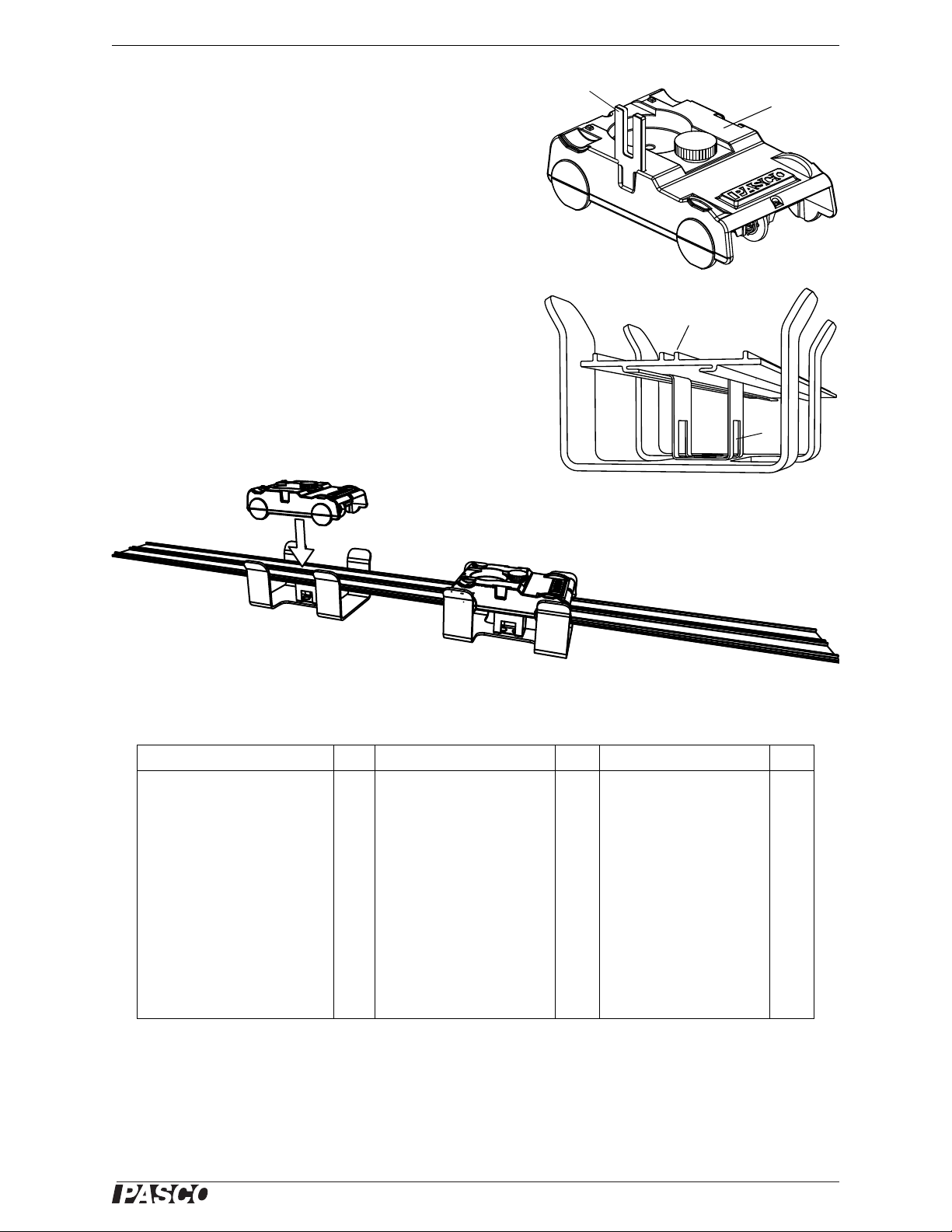
Model No. ME-7003 012-12670A About the Components
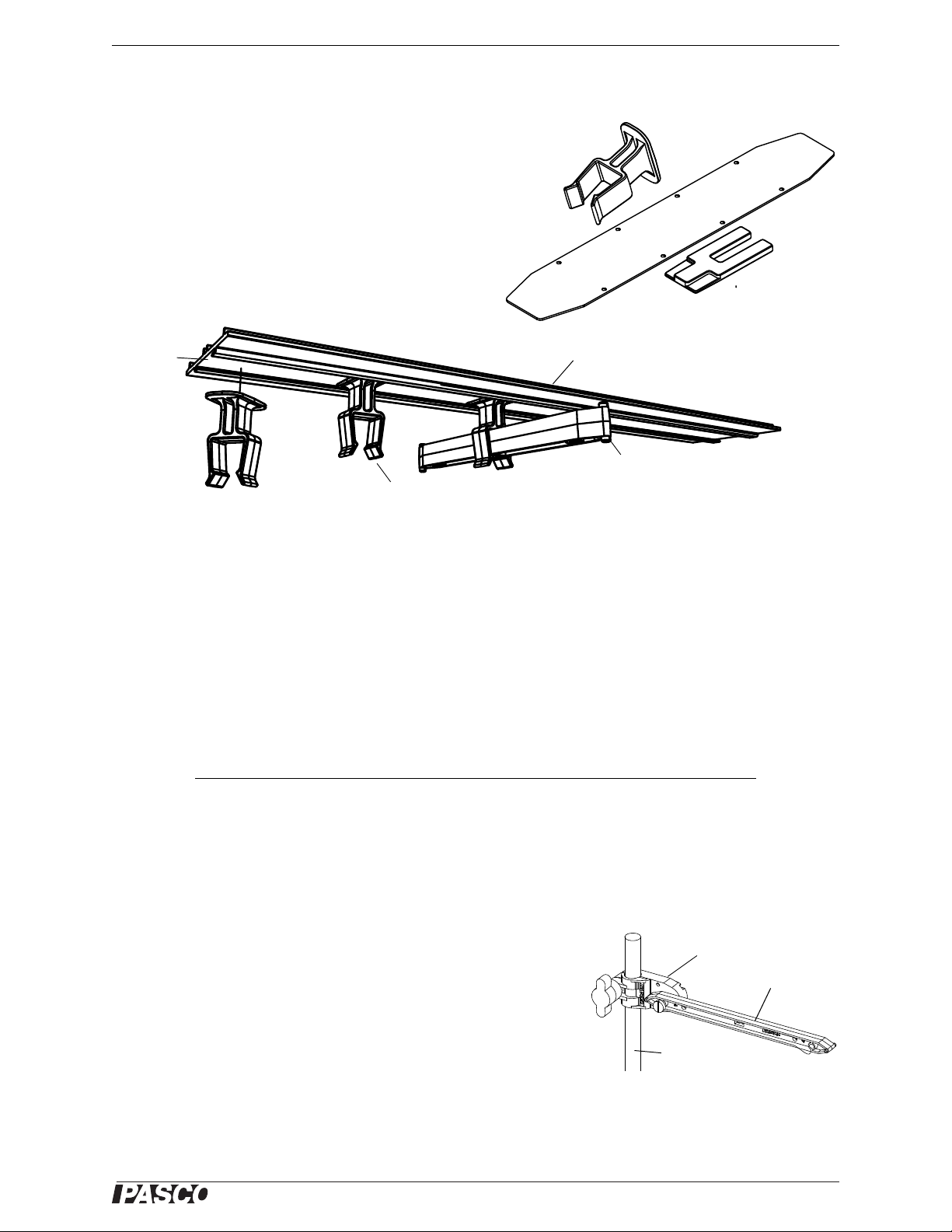
Photogate
Flag
Coupler
Track
Clip
Coaster Track
Track Clip
Rotate the clip one-quarter turn.
Beam
Channel
Beam
Clamp
Rod
About the Components
Large Structures Parts (ME-6974)
The ME-6974 Large Structures Parts set consists of two
Mini Car Photogate Flags, two Couplers for the Coaster
Track, and a set of 24 Track Clips. The Photogate Flags
mount on any Mini Car. When the flag on a moving car
travels through a photogate and interrupts the beam, the
car’s motion can be measured. The Couplers are used to
connect Coaster Tracks together, and the Track Clips are
used to connect a Coaster Track to a PASCO structure.)
Use track clips to connect the Coaster Track to the structure beams. Slide the clip into the channel on the underside
of the track. Move the clip into position and lock it into place with a quarter twist as shown.
Flexible I-Beams (ME-6985)
The Flexible I-Beam Set contains forty-six flexible beams of three dif ferent lengths . The flexible beams have the
same lengths as three of the I-beams from the Truss Set Members (ME-6993). The flexible beams allow you to
explore the concept of structural failure. By replacing a #3, #4, or #5 I-beam in a structure with one of the flexible
I-beams you can observe the effect of a load that causes deformation. These I-beams are designed to demonstrate
stress and failure and then return to their original shape once the load is removed.
Flexible I-Beam Set (ME-6985) Qty Equivalent Truss Set Members
#3 Flexible I-Beam (11.5 cm) 18 #3 I-Beam
#4 Flexible I-Beam (17 cm) 18 #4 I-Beam
#5 Flexible I-Beam (24 cm) 10 #5 I-Beam
Please note that the flexible I-beams are a different color (beige) than the other I-beams (light blue).
Structures Rod Clamp (ME-6986)
Use a rod clamp to attach a structure beam to any 12.7 mm (1/2”) diameter rod.
3
Page 8

®
Large Structures Set About the Components
#4 Beam
#3 Beam
3 X 4
Beam
Half Round
Truss
3 X 4
Beam
2 X 3
Flat #4
Beam
#1 Beam
#2 Beam
#3 Beam
#4 Beam
#5 Beam
Half Round
Connector
Screw
#1 #1
#3
#3#3
#5
#2 #2
#4
Flat Structures Members (ME-6987)
This set contains three types of flat structures: Flat 3 X 4 Beam (19 cm), Flat #4 Beam (17 cm), and Flat 2 X 3
Beam (12.5 cm). There are sixteen of each type of beam in the set.
Force Platform Structure (ME-6988A)
The PASCO model ME-7003 Force Platform Structures Bra cket includes two brack ets and fo ur thum bscrews. Th e
adapter bracket is designed to connect memb ers of the PASCO Structures System to a P ASCO Force Platform (not
included). The brackets can also serve as foundation plates for larger structure models.
(Please see the Force Platform Structures Bracket instruction sheet for more information.)
Truss Set Members (ME-6993)
The Truss Set Members consis ts of five typ es of “I- beams ” and
one type of connector. Each set has the following quantities:
Item Qty Item Qty
#1 Beam (5.5 cm) 8 #4 Beam (17 cm) 18
#2 Beam (8 cm) 8 #5 Beam (24 cm) 8
#3 Beam (11.5 cm) 18 Half Round Connector 14
When connected at 180° to a connector, two identical beams
have a combined length equal to one longer beam. For example,
two #1 beams connected at 180° have the same length as a #3
beam.
Truss Set Screws (ME-6994)
Each set of Truss Set Screws contains 75 Thumbscrews for attaching I-beams to connectors or load cells.
Cord Lock Spares (ME-6996)
A set of Cord Lock Spares includes 32 Cord Tensioning Clips (Cord Clips) and one roll of yellow braided cord.
When attaching cords for lateral bracing or for suspension or cable-stayed brid ges, Cord Clips are used to assist in
adjusting the tension in the cords.
The Cord Clip does not come apart. It is best to thread the cord through the clip before the clip is installed on the
bridge or structure. Prepare to thread the cord by holding the top half of the clip as shown in Figure A so the two
4
Page 9
®
Model No. ME-7003 012-12670A About the Components
Figure A: Hold half of
the cord clip so the
two halves separate
Figure B: Loop the
cord back through the
cord clip
Figure C: The cord
goes around the
screw hole
Figure D: The cord clip is
ready to be attached to the
structure using a screw
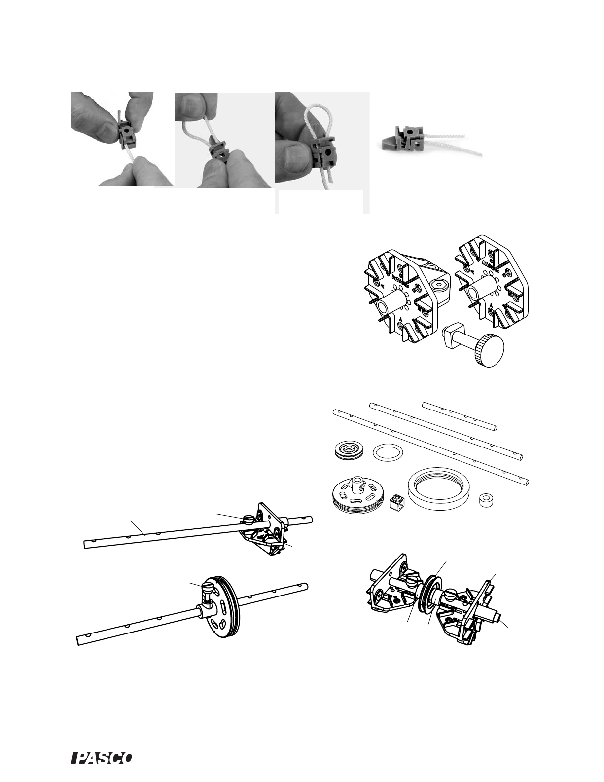
Full
Round
Flat
Round
PASt rack
Connector
Pulley
O-ring
Drive
wheel
Collet Tire Spacer
Axles
Pulley
Spacers
This pulley is free to rotate.
Half
Round
Axle
Axle attached to a half-round connector
Axle
Half
Round
Thumbscrew
Drive wheel attached to an axle
Thumbscrew
halves of the clip will separate, leaving an opening through which the cord is threaded. The cord is inserted into
the end opposite the pointed end of the clip. The cord should be looped back through the clip as shown in Figure C.
Then the Cord Clip can be used in the structure, using the attachment screw to tighten the clip shut. To adjust the
cord tension, loosen the screw and pull on the cord to the desired tension and then tighten the screw.
Full Round Connectors Spares (ME-6997)
Full Round Connector: The Full Round Connector has eleven slots,
labeled A through H and X, Y, and Z, for attaching beams. There are
six Full Round Connectors in the set.
Flat Round Connector: The Flat Connector has eight slots, labeled
A through E, and X, Y, and Z, for attaching beams. There are six
Flat Connectors in the set.
PAStrack Connector: The PAStrack Connector is a nut and bolt that
allows a PAStrack to be connected to a structures model. There are
six PAStrack Connectors in the set.
Axle Spares (ME-6998A)
The Axle Spares set includes two Axles each of three different lengths, twelve Pulleys, twelve O-rings, four Drive
Wheels, four Tires, 24 Collets, and twelve Spacers.
The illustrations show example uses of axles, pulleys, and
wheels.
5
Page 10
®
Large Structures Set About the Components
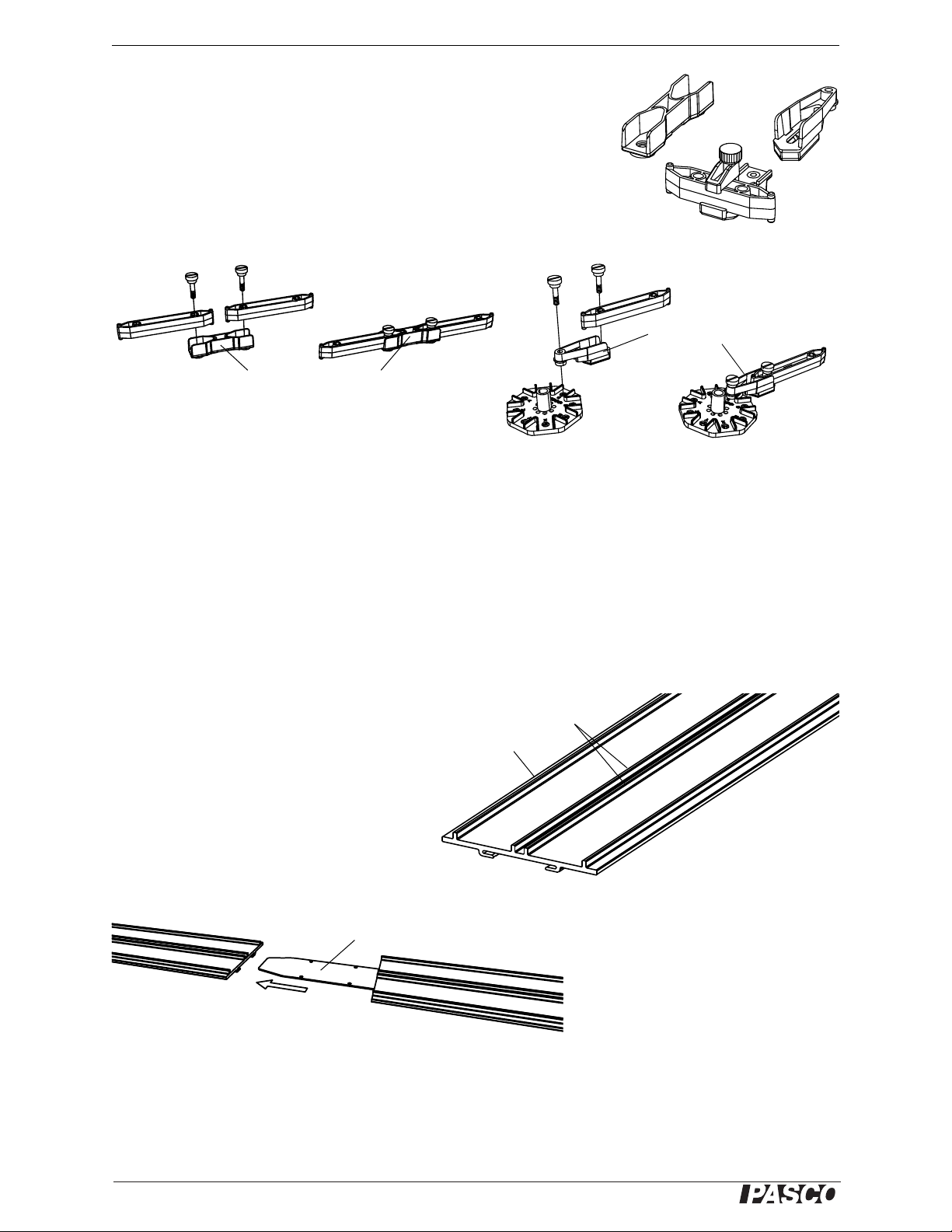
Sliding Connector on a #1 Beam
Straight
Angle
Straight Connector
Angle Connector
Side rail
Center
rails
Track
Angle Connectors (ME-6999A)
The Angle Connectors set includes 24 Straight Connectors, 24 Angle Connectors, and twelve Sliding Connectors. The Straight Connector can connect
two beams to make a longer beam. T he Angle Co nnector can allow a beam to
be connected to a half round connector, full round connector, or flat round
connector at an angle different than zero, 45, or 90 degrees. The angle connector also allows for a small adjustment of the length of the beam. The Sliding Connector allows one beam to be connected to another beam at any
position along the length of the second beam..
To use the sliding connector, loosen the thumbscrew and rotate the top “jaw” to the side. Place the beam onto the
lower part of the connector, rotate the top “jaw” into place, and tighten the thumbscrew. The Structures Set
includes two Angle Connector sets.
Connector Spares (ME-7002)
Each set of Connector Spares includes fourteen Half Round Connectors.
#6 I-Beam Spares (ME-7008)
The #6 I-Beam is 35 cm long. There are 24 beams per set.
Coaster Track (ME-9814)
The ME-9814 Coaster Track is a section of f lexible track that is 9.1 m long. Side rails and center rails help to keep a Mini Car on the track.
Use a sharp knife or scissors to cut the track to
the desired length.
Use a Track Coupler to connect two sections of
Coaster Track together.
Slide the Track Coupler into the channel on the underside of each Coaster Track section.
6
Page 11
®
Model No. ME-7003 012-12670A About the Components
Mini Car
Photogate flag
Metal
Coaster
track
Mini Car
Starter Bracket
Car aligned in bracket
Mini Cars (ME-9839 and ME-9840)
The ME-9839 Green Mini Car and ME-9840 Yellow Mini Car
are designed to run on the Coaster Track.
If you are using a photogate (available separately) to measure
the speed of the car, attach a photogate flag (included with the
ME-6974) as pictured. The flag will interrupt the photogate
twice as the car passes, allowing the speed to be calculated.
Mini Car Starter Bracket (ME-9856)
The ME-9856 Mini Car Starter Bracket is designed to help
align the wheels of the Mini Car on the Coaster Track. Squeeze
the metal clip of the starter bracket and insert it into the channel
on the underside of the track.
Slide the bracket along the track to the desired position.
Drop the Mini Car into the bracket as shown.
Total Quantities
Included Items Qty Included Items Qty Included Items Qty
#6 Beam (35 cm long) 24 #4 Flexible Beam (17 cm) 18 Force Platform Structure 2
#5 Beam (24 cm long) 24 #3 Flexible Beam (11.5 cm) 18 Cord Tensioning Clip 32
#4 Beam (17 cm long) 54 Angle Connector 24 Yellow Cord 1 roll
#3 Beam (11.5 cm long) 54 Straight Connector 24 Coaster Track (9.1 m) 1
#2 Beam (8 cm long) 64 Sliding Connector 12 Mini Car (Green and Yellow) 2
#1 Beam (5.5 cm long) 24 Flat Round Connector 6 Mini Car Starter Bracket 1
Flat 2 X 3 Beam (12.5 cm) 16 Full Round Connector 6 Track Clip 24
Flat 3 X 4 Beam (19 cm) 16 Half Round Connector 70 Track Coupler 2
Flat #4 Beam (17 cm) 16 PAStrack Connector 6 Mini Car Photogate Flat 2
#5 Flexible Beam (24 cm) 10 Screw (6-32) 450 Container (not shown) 2
7
Page 12

®
Large Structures Set Operation
Attaching beams to connectors
A load cell combined with two #2 beams is the same
length as a #4 beam
Load Cell
#2
#2
#4
Bridge with Load Cells
1.0 N()21.0 N()
2
+ 1.4 N=
Operation
Assembling Beams
All beams attach to connectors in the same way. Use the included screws (6-32, slotted) to attach beams to a con nector (such as the half round connector) as illustrated.
Adding Load Cells
To measure the compression and tension forces in individual members of a structure, add load cells (available
separately) to the PASCO Structure. Replace a beam
with two shorter beams and a load cell.
#5 beam = load cell + two #3 beams
#4 beam = load cell + two #2 beams
#3 beam = load cell + two #1 beams
Use thumbscrews to attach two beams to a load cell as
shown in the fi gure.
When using load cells, assemble your structure with the screws loose. This will simplify the analysis by ensuring
that the members experience only tension and compression without moments.
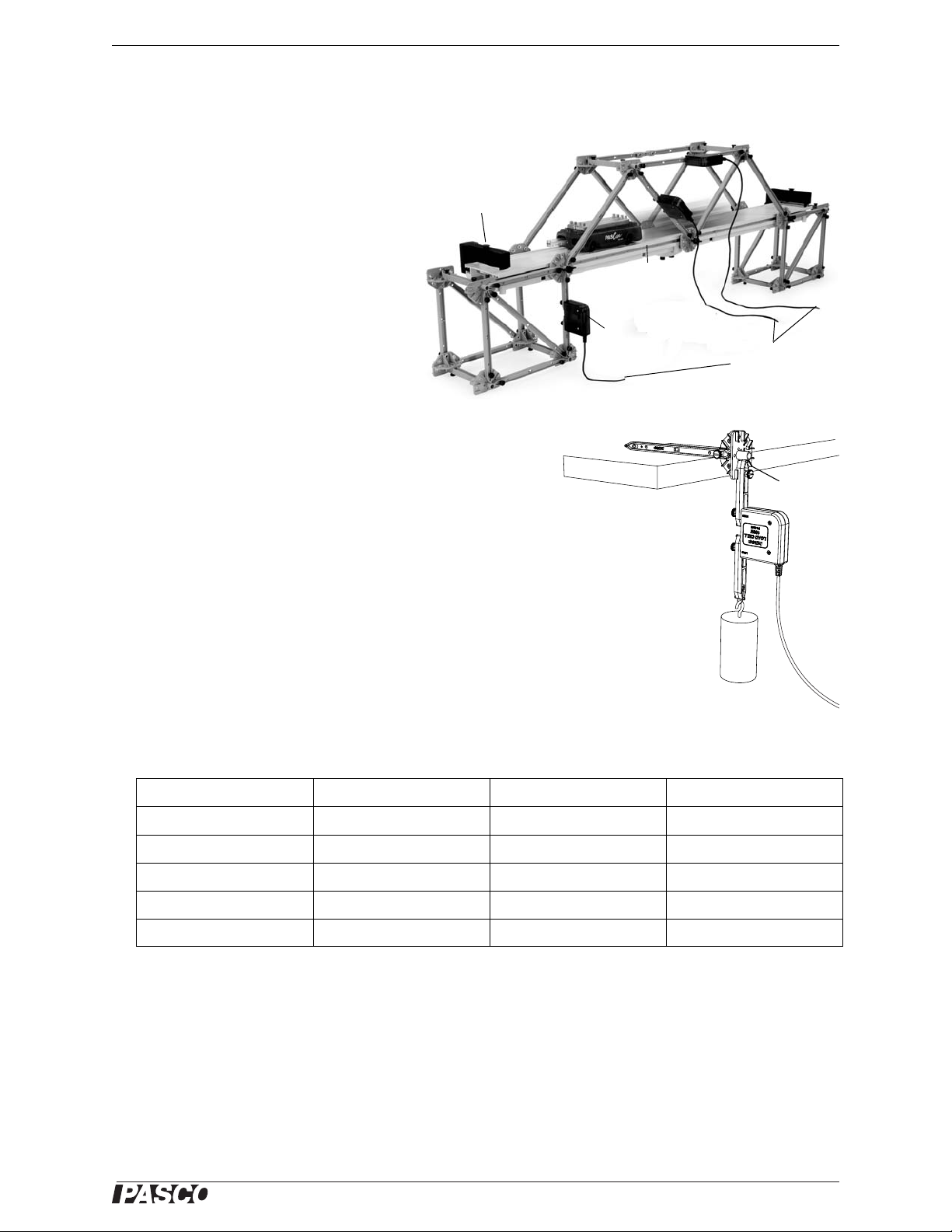
Example: Bridge with Load Cells
Static Load
The bridge shown in the figu re incorporates six load
cells to measure the tension or compression in various members. A hanging mass is used to apply loa d.
The mass is adjusted so that th e compression in one
of the legs is 1.0 N. Compression is registered as a
positive value and tension as a negative value.
If the screws are loose, then the theoretical analysis
of the bridge can be carried out by assuming that the net force at each node is zero. Thus, the vertical component
of compression in the left-most diagonal member must be 1 N (to oppose the force applied by the leg). The horizontal component must also be 1 N since the member is at a 45° angle. The predicted resultant force is:
8
Page 13
®
Model No. ME-7003 012-12670A Large Structures Construction
Recording the forces measured by the load cells as the cart traverses the
PAStrack bridge.
PAStra ck
Load
Cell
Adjustable
end stop
To Load Cell
Amplifier
Calibration fixture
Load
Cell
Mass
Half
Round
Dynamic Load
With the load cells inserted as shown in
the figure, push a Cart with its extra
mass across the bridge. Zero the load
cells before the measurement. Examine
which members are under tension or
compression.
Note that the Load Cell Amplifier can
support up to six Load Cells in any
combination (5 N, 100 N, or both).
Calibration.
See the instructions that came with the load cells for details about
how to connect the load cells to an interface or datalogger. Follow
the instructions to calibrate the load cells and use them to collect
data. (Load cells are factory calibrated; however, you can re-calibrate them in software or on the datalog ger. See the documentation
for your software or datalogger for instructions.)
Large Structures Construction
The manual illustrates construction of twenty large structures such
as trusses, bridges, and cranes. The descriptions show what components are used for each structure and how they are connected to
each other. Close-up photographs show the details of construction
where possible.
Table 1.1:
Structure Structure Structure Structure
Car Building Jump Suspension Bridge Cantilever Truss Arch Causeway
Cable Stayed Bridge High Road/Low Road Brachistochrone Skyscraper
Arch Truss Tied Arch Bridge Drawbridge House Frame
Roller Coaster Baltimore Bridge Vertical Lift Drawbridge Angle Crane
Canyon Car Jump Double Tied Arch Bridge Tower Crane Windmill
9
Page 14
®
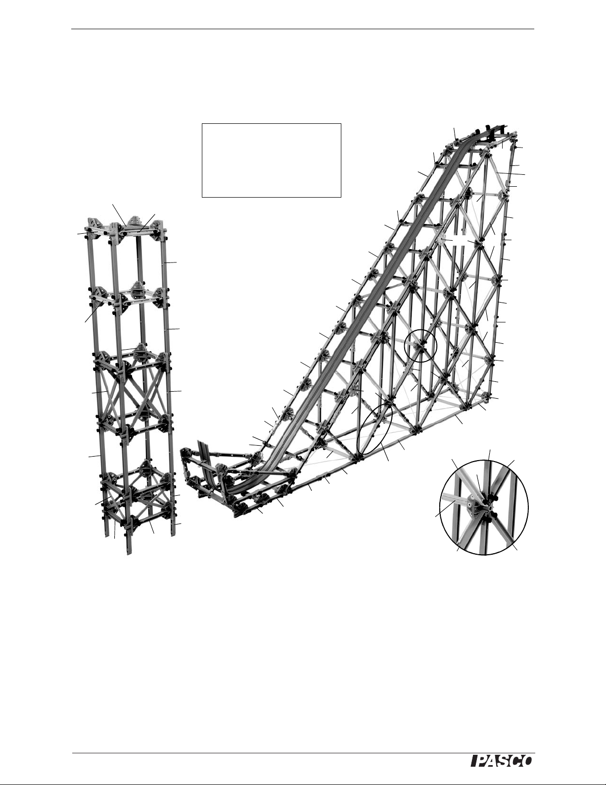
Large Structures Set Car Building Jump
Figure: Car Building Jump
Flex 4
Legend:
AC = Angle Connector
FR = Full Round Connector
FT = Flat Round Connector
HR = Half Round Connector
SL = Sliding Connector
ST = Straight Connector
AC
AC
#4
#4
#4
#4
#4
#4
ST
ST
#4
SL
#5
SL
SL
#5
#3
#3
#3
#3
#3
#3
SL
ST
#1
#3
#2
#2
#4
#6
#6
#4
#4
ST
#5
#5
#6
#6
#6
#6
#6
Use two #3 beams
and a Straight
Connector to make
twelve #5 beams.
FT
FT
HR
HR
FL
Flex 3
#4
#4
#4
#3
HR
FR
#6
#5
#5
#5
Flex 5
Flex 4
#4
#3
2 x
3 x
#2
#2
Landing
platform*
Car Building Jump
Use beams, connectors, cord (for cr os s b racing), and a section of Coaster Track to build a ramp next to a building.
Use Track Clips to attached the Coaster Track to the ramp. Add a Mini Car Starter Bracket to the top of the ramp
and let a Mini Car roll down the ramp and “jump” onto the adjacent building’s landing platform.
Flex 3
Flex 5
Flex 3
Adjust the position of the building as needed so that the car lands on top of the building.
*Make a landing platform using a square of cardboard or foam core board.
If the building is too high or too low, change the beams at the bottom of the building. Replace the #2 beams with
#1 beams, or remove the bottom beams altogether.
10
Page 15
®
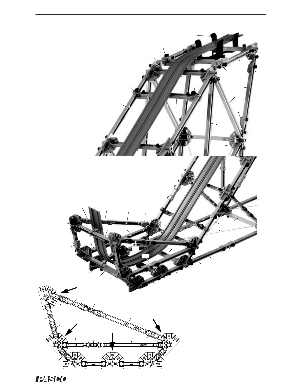
Model No. ME-7003 012-12670A Car Building Jump
Figure: Top Detail
Mini Car Starter Bracket
#4
Flex 5
AC
AC
AC
#4
SL
SL
#6
#5
AC
#4
SL
Use Track Clips to attach the Coaster
Track to the #4 cross beams. Attach the
Mini Car Starter Bracket to the underside
of the Coaster Track.
AC
AC
ST
#4
#4
AC
#2
Flex 4
Flex 4
Flex 4
#2
#2
#2
#4
ST
#4
Track Clip
#1
Track Clip
HR
HR
Cord
Use cord to cross brace
the base of the ramp.
ST
Figure: Bottom Details
For the bottom of the ramp, attach
Track Clips to the Coaster Track and
then to the #4 beams in the locations
indicated by the arrows in the diagram.
Loosen the Angle Connectors to adjust
the angle of the upward-curved section
at the end of the Coaster Track so that
the Mini Car is able to “jump” to the
top of the landing platform. Tighten the
connectors to keep the angle.
#1
#1
#2
#2
#2
#4
#2
#2
#4
AC
AC
#2
ST
#4
#2
ST
#4
AC
Car Building Jump Details
11
Page 16

®
Large Structures Set Car Building Jump
Tie the cords
to the
connectors.
Cord
Lace the
cord through
the
connectors.
Cord
Cord
Cord
Tensioning
Clips
Figure: Back of Ramp Details
Tie the
cords.
Lace the
cords.
Cord
Tensioning
Clip
Cord
Tensioning
Clip
Car Building Jump Details
Use cord and Cord Tensioning Clips to cross brace the back of
the ramp.
Tie the cords to the Half Round Connectors near the top of the
ramp,
Lace the cord through holes in the Half Round Connectors that
are between the top and bottom of the back of the ramp.
12
Attach the cords to Cord Tensioning Clips on the bottom connectors.
Page 17

®
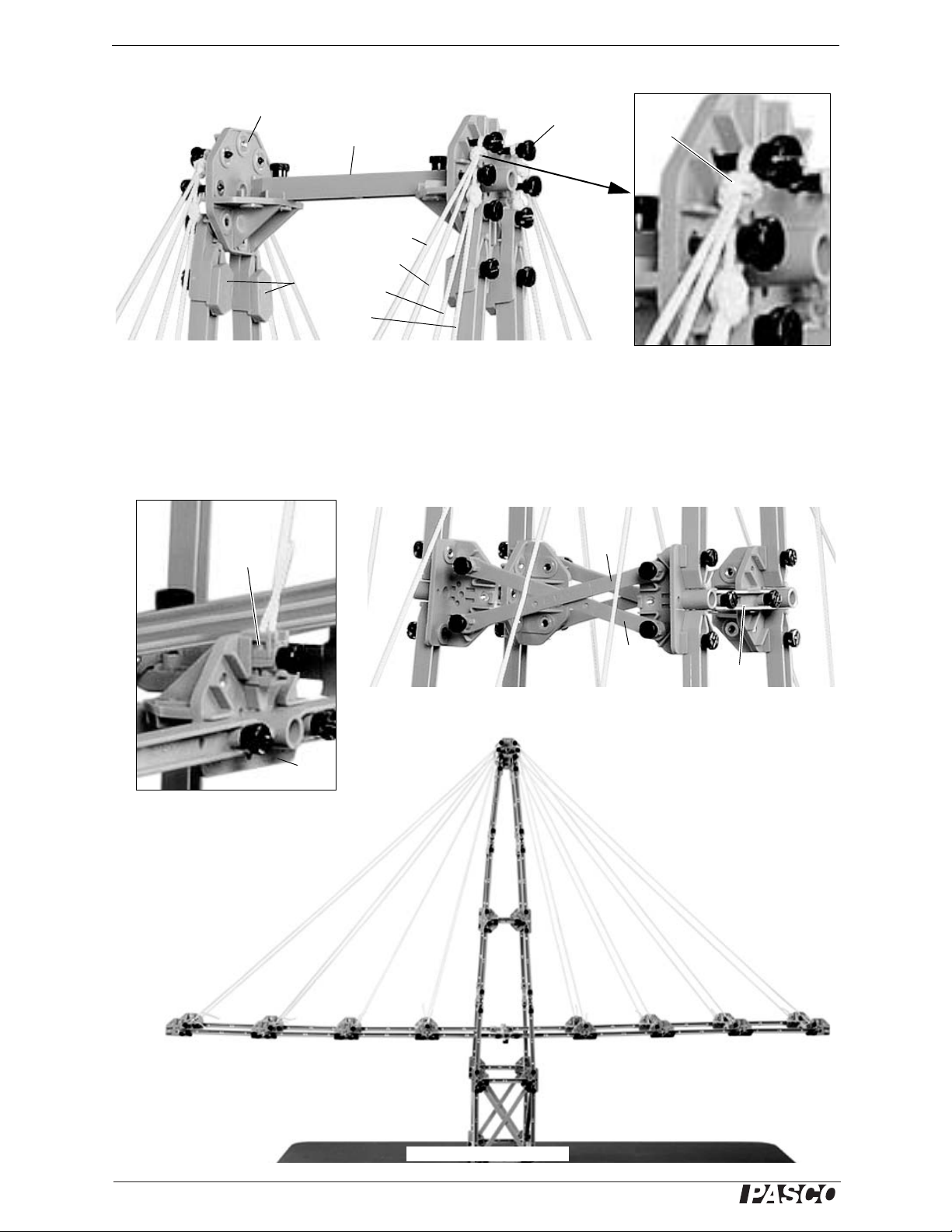
Model No. ME-7003 012-12670A Cable Stayed Bridge
Figure: Cable Stayed Bridge
#3
#6
#6
#4
Flat 4
#5
Flat 4
#5
#4
#5
AC
AC
AC
ST
#3
#2
AC
#4
#3
SL
Legend:
AC = Angle Connector
FR = Full Round Connector
FT = Flat Round Connector
HR = Half Round Connector
SL = Sliding Connector
ST = Straight Connector
FT
#4
#3
AC
FR
#2
3 x 4
2 x 3
Tow er s
Deck
Deck
Support
Struct ure
#4
#4
Cord
Tensioning
Clip
Coaster Track
Cable Stayed Bridge
The Cable Stayed Bridge has a d eck that is susp ended on cords fr om two towers. There is a deck support s tructure
at each end of the deck.
The modular approach to the construction of this structure is to build the deck in two halves and also build each
tower and deck support structure before trying to suspend the deck. Do not attach the Coaster Track to the deck
halves yet. Next, insert one half of the deck through one of the towers and use cord to suspend the deck from the
top of the tower. Repeat for the other half of the deck. Connect the ends of the deck halves to the deck support
structures and then connect the deck halves between the towers. Adjust the length of the cords so that the deck is
level. Finally, use T rack Clips to attach the Coaster Track to the finished deck..
13
Page 18
®
Large Structures Set Cable Stayed Bridge
#3
FR
Screw
D
C
B
A
Overhand
knot
Figure: Tower Detail
AC
HR
Cord
Tensioning
Clip
#2
2 x 3
2 x 3
At the middle of the tower, use 2 x 3 beams to cross brace the tower.
ABCD
Figure: Suspend the Deck
DCBA
Cable Stayed Bridge Details
There are eight strands of cord from each side of the top of the tower that are used to suspend each half of the deck.
Start with the strands of cord closest to the tower (for example, A and B in the figure). Get a piece of cord that is
twice as long as the distance from the top of the tower to the deck. Make an overhand knot near the middle of the
piece of cord and fasten the loop of the knot to the Full Round Connector at the top of the tower using a screw as
shown. Put the two ends of the cord into Cord Tensioning Clips and attach the clips to two of the Half Round Connectors on the side of the deck. Repeat the process for strands C and D and the rest of the strands of cord.
14
Page 19

®
Model No. ME-7003 012-12670A Arch Truss Bridge
Figure: Arch Truss Bridge
#4
#4
#6
#6
#5
#5
#3
#2
ST
Legend:
AC = Angle Connector
F4 = Flat 4 Member
FR = Full Round Connector
FT = Flat Round Connector
HR = Half Round Connector
SL = Sliding Connector
ST = Straight Connector
#4
#3
#4
FR
F4
3 X
FT
F4
AC
ST
ST
#1
#3
SL
Flex 3
Flex 5
Flex 3
Flex 5
AC
AC
#1
ST
#3
AC
AC
AC
#2
Cord
Cross
brace with
cord.
Cross brace with 3 X 4.
Cross brace with 3 X 4.
Figure: Arch Truss Top Detail
Flex 5
Flex 5
#1
SL
SL
ST
ST
#1
#4
AC
#2
Arch Truss Bridge
The Arch Truss design is one of the most frequently used designs in history. Construct the end supports and then
add the deck. Tie cords from the base of one end support to the base of the other end support. Next, add the arch
and suspension beams. Use Flat 3 X 4 members to cro ss brace the deck at the point where it joins the top of the end
supports. Use cord to cross brace the bottom sections of the arch. Finally, use Track Clips to attach the Coaster
Track.
Connect the
center of the
arch with
Straight Connectors and a #1
Beam.
Use Sliding
Connectors and
#1 Beams to
suspend the
center of the
arch.
15
Page 20

®
Large Structures Set Arch Truss Bridge
Figure: Arch Truss Bridge Details
ST
SL
AC
FR
FL
Cord
Tensioning
Clip
Tie a knot.
ST
ST
SL
AC
AC
AC
ST
#3
#1
#1
#3
Flex
#3
Figure: Arch Truss Bridge Bottom
Arch Truss Bridge Details
Use two pieces of cord to cross brace the two lower
sections of the arch. Attach the cords with Cord
T ensioni ng Clips at one end. Lace the cords through
the Sliding Connectors. Tie the cords to holes in the
Full Round Connectors at the other end..
Repeat for the other side of the bridge.
Bridge Details
16
Page 21

®
Figure: Roller Coaster Left Detail
#4
#1
Use a cord to stop
the Mini Car.
AC
AC
ST
#3
#4
#4
#4
#5
FR
#4
#6
#5
#6
Flex 5
#5
Legend:
AC = Angle Connector
CT = Cord Tensioning Clip
F4 = Flat 4 Member
FR = Full Round Connector
FT = Flat Round Connector
HR = Half Round Connector
SL = Sliding Connector
ST = Straight Connector
#4
AC
AC
Flex 4
#4
AC
#4
#5
ST
#3
AC
#4
Knot
#6
Cord
CT
SL
#5
Track
Clip
3 X 4
Model No. ME-7003 012-12670A Roller Coaster
Roller Coaster
Use set components to build a “loop-the-loop” roller coaster model.
17
Page 22

®
Large Structures Set Roller Coaster
Figure: Roller Coaster Right Details
#6
#6
#6
Legend:
AC = Angle Connector
CT = Cord Tensioning Clip
F4 = Flat 4 Member
FR = Full Round Connector
FT = Flat Round Connector
HR = Half Round Connector
SL = Sliding Connector
ST = Straight Connector
#4
#3
#3
#6
“#5” = #3 + ST + #3
“#5”
“#5”
#5
#5
Flex 5
#4
AC
AC
FT
FR
Flex 5
#4
“#5”
#6
#6
#6
“#5”
#4
AC
SL
SL
Flex 4
AC
SL
#4
Mini Car Starter Bracket
AC
SL
#4
#4
#4
Roller Coaster Details - Right End
Make fourteen extra “#5” Beams using fourteen Straight Connectors and twenty-eight #3 Beams. Use cord to
cross brace the bottom and the back of the ramp.
18
Page 23

®
Model No. ME-7003 012-12670A Roller Coaster
Figure: Roller Coaster Center Details
#6
#6
#5
#5
#5
FR
#6
#5
#3
#3
#3
#3
#3
#2
#1
#1
#4
#1
AC
#2
#5
3 X 4
3 X 4
SL
SL
FR
2 X 3
SL
SL
#1
AC
#2
#5
Figure: Roller Coaster Inset Details
#4
Roller Coaster Details - Center
Attach the Track Clip to a Flexible #4 Beam at the top of the Roller Coaster.
19
Page 24

®
Large Structures Set Canyon Car Jump
Figure: Canyon Car Jump Landing Ramp
Legend:
AC = Angle Connector
CT = Cord Tensioning Clip
F4 = Flat 4 Member
FR = Full Round Connector
FT = Flat Round Connector
HR = Half Round Connector
SL = Sliding Connector
ST = Straight Connector
#5
#4
#4
3 X 4
AC
AC
#4
#5
#5
#4
#2
#3
ST
AC
#3
#3
#4
#5
#4
#5
CT
AC
AC
AC
#1
CT
AC
CT
#4
Tie a knot.
Coaster
Track
Trac
k
Landing
Ramp
Launch
Ramp
Canyon Car Jump
Use beams, connectors, clips and cord to construct a landing ramp.
Use cord and Cord Tensioning Clips to cross br ace b oth ends of the landin g ramp. Also use cord to cross brace the
side panels at the right-hand end of the landing ramp. Use Track Clips to attach two sections of Coaster Track
side-by-side to the #4 Beam cross members.
20
Page 25

®
Model No. ME-7003 012-12670A Canyon Car Jump
Figure: Canyon Car Jump Launch Ramp
#1
ST
#6
#6
AC
#5
SL
3 X 4
#3
AC
#6
#5
#5
#6
#6
Legend:
AC = Angle Connector
CT = Cord Tensioning Clip
F4 = Flat 4 Member
FR = Full Round Connector
FT = Flat Round Connector
HR = Half Round Connector
SL = Sliding Connector
ST = Straight Connector
#3
#3
“#5” = #3 + ST + #3
“#5” = #3 + ST + #3
“#5” = #3 + ST + #3
“#5”
“#5”
“#5”
#4
#6
#6
#6
FL
“#5”
FL
#5
Flex 5
Flex 5
#5
#3
SL
AC
FR
#3
#4
#4
Figure: Canyon Car Jump Ramp Detail
SL
AC
AC
#3
#3
SL
AC
AC
SL
A
#5
#3
#3
FR
#4
AC
SL
#4
#3
Track
Clip
Mini Car Starter Bracket
AC
Canyon Car Jump Launch Ramp.
Use connectors, cord,
clips, and beams to
construct a launch
ramp. Include a Mini
Car Starter Bracket at
the top of the ramp
Make fourteen “#5”
Beams using fourteen Straight Connectors and twenty-eight
#3 Beams.
Use cord and Cord
Tensioning Clips to
cross brace the bottom and back of the
launch ramp.
Use Track Clips to
attach the Coaster
Track to the #4 B eam
cross members.
Add the Mini Car
Starter Bracket.
21
Page 26

®
Large Structures Set Suspension Bridge
End
Support
To we rs
Deck
Arch
Figure: Suspension Bridge
Legend:
AC = Angle Connector
CT = Cord Tensioning Clip
FR = Full Round Connector
FT = Flat Round Connector
HR = Half Round Connector
SL = Sliding Connector
ST = Straight Connector
#4
#4
#3
Long
Axle
#5
3 X 4
#4
#4
#4
#4
#3
3 X 4
#2
2 X 3
Flex 3
Flex 4
Flex 4
Flex 5
ST
ST
ST
SL
#1
Medium
Axle
Collet
FT
#6
3 X 4
FR
HR
#3
CT
#3
#4
#3
#1
#1
Track Clip
Flex 3
FR
Long
Axle
Put a Collet at the
middle of the Long
Axle. Attach a Track
Clip to the Collet.
AC
Cord
Suspension Bridge
The construction of the Suspension Bridge uses a modular approach. The construction involves building the End
Supports, Towers, Arches, and Deck, and then suspending the Deck from the Arches and connecting the Deck to
the End Supports.
22
Page 27

®
Model No. ME-7003 012-12670A Suspension Bridge
Medium
Axle
Collet
Sliding
Connector
Screw
through
Collet
Straig ht
Connector
Flat Round
Connector
Angle
Connector
Figure: Suspension Bridge Tower Detail
#1
Straig ht
Connector
Sliding
Connector
#1
Flat Round
Connector
Collet
Screw through
Collet
Figure: Suspension Bridge Tower Detail Sketch
Collet
Long Axle
Track Clip
Half
Round
Full
Round
3 X 4
#4
3 X 4
#3
Figure: Suspension Bridge End Support Detail
Suspension Bridge Details
Put a screw through the center hole of a Collet and attach the screw to the Flat Round Connector. Clamp the jaws
of the Sliding Connector over the Collet. Connect a #1 Beam to the Sliding Connector and connect a Straight Connector to the #1 Beam. Repeat for the other arches.
Suspend the deck from the arches using cord and Cord Tensioning Clips. Tie one end of each cord to the arch and
attach the other end of the cord to the Cord Tensioning Clip.
Connect the end of the deck to the end support. Put one end of a Long Axle through
the Half Round Connector of the end support and the Full Round Connector of the
deck, Add a Collet to the Long Axle and
then put the Long Axle through the Full
Round Connector and Hal f Ro und Con nector on the other side to attach the end of the
deck to the end support. Position the Collet
at the middle of the Long Axle and use a
Track Clip to attach the Coaster Track to
the Collet on the axle.
23
Page 28

®
Large Structures Set High Road/Low Road
#6
#6
#6
Legend:
AC = Angle Connector
CT = Cord Tensioning Clip
FR = Full Round Connector
FT = Flat Round Connector
HR = Half Round Connector
SL = Sliding Connector
ST = Straight Connector
#4
AC
Long Axle
#5
#5
#3
#3
#6
#4
#4
#5
#5
#5
#3
3 X 4
#6
#2
#4
#1
#1
SL
SL
#4
#6
Use cord and
Cord
Tensioning
Clips to cross
brace the
back of the
starting ramp.
Use cord and Cord
Tensioning Clips to cross
brace the base of the
starting ramp.
FR
AC
Figure: High Road/Low Road Starting Ramp
Use 2 X 3
Flat Members
to cross
brace the
base of the
starting ramp.
2 X 3
Slotted masses
SL
High Road/Low Road
Build a support for two Coaster Tracks side-by- side. One Coaster Track (the “High Road”) has a constant gradual
slope from start to finish. The oth er C oaster Track (the “Low Road”) has a steep drop near the start and an equ ally
steep rise near the end. If two Mini Cars start together on the two “roads”, which car finishes first?
24
Page 29

®
Model No. ME-7003 012-12670A High Road/Low Road
Long Axle
Collet
Collet
Collet on Axle
Track Clip
on Collet
High Road
Coaster Track
Low Road
Coaster Track
Figure: Starting Ramp Reverse View
#6
#6
#1
#4
#4
AC
AC
Long Axle goes here.
SL
#2
#3
3 X 4
2 X 3
#3
Use #3 Beams as
cross members on the
Low Road.
Use #2 Beams as
cross members on the
High Road.
FR
High Road/Low Road Details
The Long Axle extends through the support structures at the starting ramp for both the High Road and the Low
Road.
This illustration shows the High Road/Low Road starting ramp from anot her angle.
25
Page 30

®
Figure: High Road/Low Road Finishing Ramp
#3
#4
#4
#4
#2
#3
#4
AC
AC
ST
#5
#3
#4
#5
#3
#3
FT
#6
SL
SL
SL
#6
Legend:
AC = Angle Connector
CT = Cord Tensioning Clip
FR = Full Round Connector
FT = Flat Round Connector
HR = Half Round Connector
SL = Sliding Connector
ST = Straight Connector
#4
#3
#4
AC
#1
CT
FR
Use 2 X 3 Flat
Members to cross
brace the base of
the finish ramp.
3 X 4
#4
Figure: Tied Arch Bridge
Legend:
AC = Angle Connector
CT = Cord Tensioning Clip
F4 = Flat 4 Member
FR = Full Round Connector
FT = Flat Round Connector
HR = Half Round Connector
SL = Sliding Connector
ST = Straight Connector
#4
#3
#3
#2
#4
#6
#5
3 X 4
AC
#2
ST
#3
AC
#4
#4
#4
#4
#4
#4
ST
ST
AC
F4
Cord
F4
Flex 5
Flex 5
F4
#4
CT
Tie a
knot.
Use cord and
CT clips to
cross brace.
Use cord to
catch the
Mini Cars.
Large Structures Set Tied Arch Bridge
High Road/Low Road Details
This view shows the finishing ramp..
Tied Arch Bridge
26
Flex 5
#4
F4
Page 31

®
Model No. ME-7003 012-12670A Tied Arch Bridge
Figure: Tied Arch Bridge End Support
Flex 4
FL
FR
Medium
Axle
#6
#6
#5
AC
SL
SL
#1
AC
FL
FR
#5
#5
#3
ST
CT
#1
SL
#3
#5
#4
#3
Track
Clip
Long
Axle
Long
Axle
Slotted
masses
#2
Coaster
Track
HR
Cord
Cord
AC
Tied Arch Bridge Details
Use a #3 Beam and two Sliding Connectors to support the slotted masses at the back of the end support.
Use cord and Cord Tensioning Clips to cross brace the back of the end support. Tie cords between the bottoms of
the two end supports.
27
Page 32

®
Large Structures Set Baltimore Bridge
Figure: Tied Arch Bridge Top Detail
#3
#3
#4
#4
#4
#4
#4
#4
#3
#3
F4
F4
F4
Flex 5
Flex 5
Flex 5
Flex 5
Flex 3
Flex 3
#4#4
Flex 5
Flex 3
FT
F4
F4
F4
F4
FT
Figure: Baltimore Bridge
Flex 3
FT
#5
#5
#6
#6
#6
#6
#6
#4
#4
#4
#4
#4
#4
#4
#4
#3
#4
Flex 4
Flex 4
#5
Support the
slotted
masses on
a #4 Beam.
Tied Arch Bridge Details
At the top of the Arch, use a Flat Round Connector and four Flex 3 Beams to form a cross brace.
Baltimore Bridge
Use 40 #3 Beams and twenty Straight Connectors to make twenty extra “#5 Beams”.
Use Flat Round Connectors and four Flexible #3 Beams to make four cross braces for the deck. Place one at each
end of the deck where it joins the end support and put the other two on both sides of the center of the deck.
28
Page 33

®
Model No. ME-7003 012-12670A Baltimore Bridge
Flex 5
Flex 4
Flex 4
F4
F4
F4
#6
#6
F4
Cord
CT
Cord
FR
3 X 4
Cord
Cord
Cord
Legend:
AC = Angle Connector
CT = Cord Tensioning Clip
F4 = Flat 4 Member
FR = Full Round Connector
FT = Flat Round Connector
HR = Half Round Connector
SL = Sliding Connector
ST = Straight Connector
Track
Clip
Figure: Baltimore Bridge Details
Baltimore Bridge Details
Use cord and Cord Tensioning Clips to add cross bracing to each panel on t he top of the truss and to several of the
diagonal panels. Use Flexible #5 Beams to cross brace several of the panels of the deck.
29
Page 34

®
Large Structures Set Baltimore Bridge
Cord
Cord
FR
#5
#6
FT
Flex 3
Cross brace
structure
Flex 4
F4
F4
F4
#6
#6
Baltimore Bridge Details
Use a Full Round Connector at the center of the bridge.
Add two of the cross brace structures to
the deck on both sides of the center of
the deck.
Figure: Baltimore Bridge Details
30
Page 35

®
Model No. ME-7003 012-12670A Double Tied Arch Bridge
Legend:
AC = Angle Connector
CT = Cord Tensioning Clip
F4 = Flat 4 Member
FR = Full Round Connector
FT = Flat Round Connector
HR = Half Round Connector
SL = Sliding Connector
ST = Straight Connector
FT
Medium
Axle
#5
FR
#5
#4
#4
#3
F4
ST
#1
#6
#5
#4
#5
#5
3 X 4
#2
ST
Flex 3
Flex 5
#3
3 X 4
Flex 4
Flex 4
Flex 3
ST
ST
SL
SL
Flex 5
Flex 5
#1
Flex 4
#4
#5
#6
#4
#4
#4
#4
#4
FT
FT
AC
FR
Figure: Double Tied Arch Bridge
Medium
Axle
FT
#1
ST
#6
FR
Collet
on Axle
Track
Clip
#3
#4
3 X 4
AC
#5
#5
#4
F4
FT
Figure: Double Tied Arch Bridge Detail
Double Tied Arch Bridge
In the end supports, put a Collet in the middle of the Medium Axle and use a T rack C lip
to attach the Coaster Track to the Collet. Use
a 3 X 4 Flat Beam to cross brace the top of
the end support.
31
Page 36

®
Large Structures Set Double Tied Arch Bridge
Figure: Arch Details
#4
#4
#3
Flex 4
Flex 4
Flex 4
Flex 4
Flex 5
Flex 4
Flex 5
Flex 3
Flex 5
3 X 4
SL
#1
#1
#1
#1
SL
SL
ST
ST
#1
CT
CT
Figure: Cords and Cord Tensioning Clips
Cord
Double Tied Arch Bridge Details
Use cord and Cord Clips to support the deck from both sides of the arch..
Note that there are three different positions on the
Half Round Connector for the Cord Clip. Choose
the position that makes the cord as vertical as possible.Adjust the length of the cords to make the deck
level.
Add Masses
The mass hanger usually hangs from the #3 Beam
that is near the #1 Beam where the 5 N Load Cell
will be attached.Re-adjust the tension in the supporting cords to make the Deck level and give the
bridge is proper shape.
32
Page 37

®
Model No. ME-7003 012-12670A Cantilever Truss Bridge
Figure: Cantilever Truss Bridge
Legend:
AC = Angle Connector
CT = Cord Tensioning Clip
F4 = Flat 4 Member
FR = Full Round Connector
FT = Flat Round Connector
HR = Half Round Connector
SL = Sliding Connector
ST = Straight Connector
#3
ST
#3
SL
#3
#3
#6
Flex 3
#5
#4
F4
#4
#4
#4
#5
#2
#1
ST
SL
SL
FR
Flex 3
#4
#3
FR
AC
AC
AC
#4
#4
#4
3 X 4
#3
CT
Cord
Slotted
Masses
3 X 4
#5
3 X 4
3 X 4
Figure: Tower Details
#3
#4
#5
#6
#3
#3
ST
AC
AC
AC
#6
#3
#4
#4
#3
#2
ST
Flex 5
Flex 5
AC
AC
SL
AC
CT
Knot
FR
Cord
Flex 3
FR
#2
#1
#3
2 X 3
#3
F4
#4
#4
#4
F4
Cantilever Truss Bridge
The Cantilever Truss Bridge balances the torque on one side of the center tower with the torque on the other side.
Use cord and Cross Tensioning Clips to cross brace the top section of the truss at the end of the bridge. Use Track
Clips to attach the Coaster Track to the #3 Beam cross members. On each “arm” of the bridge, use a Flat 3 X 4
Member to cross brace the first section and the fifth section (counting from the end toward the tower).
Cantilever Truss
Bridge Tower Details
Use cord and Cross Tensioning
Clips to cross brace the top sections of the truss tower. Use Full
Round Connectors at the top and
the bottom of the #6 Beams at
the center of the tower. Use two
Sliding Connectors and a #3
Beam as a cross member
between the #6 Beams at the
center of the tower.
33
Page 38

®
Large Structures Set Brachistochrone
#5
#4
#4
#4
#4
#4
#4
#4
#4
#4
#4
#4
Legend:
AC = Angle Connector
CT = Cord Tensioning Clip
F4 = Flat 4 Member
FR = Full Round Connector
FT = Flat Round Connector
HR = Half Round Connector
SL = Sliding Connector
ST = Straight Connector
FR
#1
Flex 5
Flex 4
AC
#2
AC
AC
#3
#3
#1
ST
#6
#5
#4
#6
FR
3 X 4
2 X 3
AC
AC
AC
ST
FR
FT
FT
Figure: Brachistochrone
Cord
CT*
AC
Flex 4
Flex 4
Flex 4
AC
#2
#2
#1
2 X 3
SL
SL
ST
#3
#1
2 X 3
*Do not tighten the
Cord Tensioning Clip
on the cord next to the
finish line. Leave extra
cord so that the cord
can slide through the
clip when the Mini
Cars hit the cord.
SL
See the next page for a
more detailed view of
the ramp structure.
Inverted
cycloid
Point on
circle
Brachistochrone
curve
Ramp
Brachistochrone
curve
A
B
Brachistochrone
The word “brachistochrone” is from the Greek words meaning “shortest” (Βραχιοτοζ) and “time” (χρονοζ).
Imagine two fixed points in a vertical plane so that one of the points is not directly below the other. If a particle
starts from rest at one of the points and descends to th e other point under its own weight, t he brachistochrone is the
path the particle must take to reach its destina tion in the br iefest time. The brachistochrone may not be the shortest
path, but it is the quickest path..
AC
SL
#4
AC
#3
#5
#6
#5
#1
Track
Clip
Set up the structure with two Coaster Tracks side-by-side. Place two Mini Cars at different starting points on the
track and let them go. What happens?
Use cord and Cord Tensioning Clips to cross brace the back of the high end of the ramp.
The brachistochrone curve is p art of an
inverted cycloid. A cycloid is the path
of a point that is fixed on the edge of a
circle as the circle rolls along a straight
line.
Imagine a straight ramp and a brachistochrone curve as shown. In a race
from A to B between a ball rolling
down the brachistochrone curve and a
ball rolling down the straight ramp,
which ball will finish first?
34
#5
#6
Page 39

®
Model No. ME-7003 012-12670A Drawbridge
Flex 4
Flex 4
Flex 4
2 X 3
SL
SL
FR
FT
FT
2 X 3
#5
#6
FT
#4
AC
#3
ST
#1
AC
#2
#3
ST
#1
AC
AC
AC
Flex 4
Flex 5
Flex 5
Flex 5
Flex 4
#5
#6
AC
#3
Flex 4
#6
Figure: Brachistochrone Details
Figure: Drawbridge
#6
#6
#6
#6
#2
#3
ST
#3
AC
AC
#2
AC
AC
ST
Flex 4
Flex 3
#4
#4
#5
#5
3 X 4
3 X 4
#3
#3
#3
#4
#4
#4
#4
#4
#4
#4
#3
#5 (as cross brace)
#3
#2
ST
AC
Legend:
AC = Angle Connector
CT = Cord Tensioning Clip
F4 = Flat 4 Member
FR = Full Round Connector
FT = Flat Round Connector
HR = Half Round Connector
SL = Sliding Connector
FR
FR
AC
#3
#6
#6
#5
(as cross brace)
Long Axle
SL
SL
#4
#4
#5
Coaster Track
Brachistochrone Details
Drawbridge
The drawbridge structure is a “working” model. You can use parts from the ME-6984 Structures Hydraulic System
(not included*) in order to raise and lower the drawbridge. Use #4 Beams or Flexible #4 Beams as cross members
on the bridge support section. Use two #3 Beams and a Straight Connector to build extra #5 Beams. Use two #2
Beams and a Straight Connector to ma ke extra #4 Beams. Note: Additional members from PASCO Structures Sets
are needed in order to extend the right hand end of the bridge shown in the illustration.
(*See the PASCO catalog or the PASCO Web site at www.pasco.com for information about the
ME-6984 Structures Hydraulics System.)
35
Page 40

®
Large Structures Set Drawbridge
3 X 4
Cord
Cord
Cord
Cord
CT
CT
#2
#2
ST
Cord
#4
#5
AC
AC
#5
SL
Long Axle (pivot)
#6
#6
#6
#6
#4
#4
SL
SL
Legend:
AC = Angle Connector
CT = Cord Tensioning Clip
F4 = Flat 4 Member
FR = Full Round Connector
FT = Flat Round Connector
HR = Half Round Connector
SL = Sliding Connector
FT
#5
Figure: Drawbridge Details
Figure: Drawbridge Pivot and Support
#4
#4
#4
#5
#5
#5
#4
#5
#4
SL
SL
Coaster Track
#3
#2
AC
AC
ST
This view shows the
bridge in the “down”
position. Items in bold
font are part of the
bridge. Other items are
part of the support.
#5
#5
#3
HR
Long Axle
FT
HR
#4
#2
#2
AC
Cord
FT
FT
Collet
SL
#3
1-kg
#3
#4
#3
#4
AC
Tie the two
cords to the
#3 Beam.
Tie the two cords
to this Beam.
#3
CT
Drawbridge Details
Use #3 Beams as cross
members on the bridge.
Use cord and Cord Tensioning Clips to cross
brace sections of the
bridge and the bridge support.
#4
#5
Support the slotted masses
on a #4 Beam with Sliding
Connectors at each end.
#5
Slotted
masses
36
Page 41

®
Model No. ME-7003 012-12670A Drawbridge
Figure: Drawbridge Syringe
#5
#5
#2
SL
Flex 4
Flex 4
Pulley
Collet
#2
FT
Medium Axle
#1
Medium Axle
FT
Short Axle
(through second
mounting hole)
Collet
Pulley
HR
Short
Axle
Medium
Axle
Medium
Axle
Hydraulic
Cylinder
Pulley
Collet
Pulley
Collet
#2
#2
#1
Cord
Cord
Cord
Tie one end of the cords
to the front medium axle.
Tie the other end of the
cords to the #3 Beam on
the drawbridge.
#1
This beam is a “stop”
for the bridge in the
open position.
Slotted
masses
Hydraulic
Cylinder
Drawbridge Syringe Details
Figure: Drawbridge Syringe Details
37
Page 42

®
Large Structures Set Drawbridge
Flex 4
#3 or Flex 3
3 X 4
#4
#5
#3
#2
ST
FR
SL
SL
3 X 4
#4 or
Flex 4
AC
AC
Figure: Drawbridge Right Side
Slotted
masses
Drawbridge Details Continued
Use a #4 Beam or Flexible
#4 Beam and two Sliding
Connectors to form a
“stop” bar for the drawbridge when it is in the
closed position.
38
Page 43

®
Model No. ME-7003 012-12670A Vertical Lift Drawbridge
Figure: Vertical Lift Drawbridge
Bridge in the
“up” position.
Bridge in
the “down”
position.
Legend:
AC = Angle Connector
CT = Cord Tensioning Clip
F4 = Flat 4 Member
FR = Full Round Connector
FT = Flat Round Connector
HR = Half Round Connector
SL = Sliding Connector
#4
#3
#2
#1
AC
AC
ST
#4
#4
#4
#3
#5
#3
F4
#6
#3
SL
#3
SL
#2
AC
3 X 4
#4
F4
#5
#4
#3
#4
FR
FT
#2
#6
Long
Axle
Medium Axle
#6
#6
#6
F4
#4
#4
#4
#4
#4
#4
#5
#5
SL
Flex 3
Flex 3
Long
Axle
Medium
Axle
#2
#3
#3
3 X 4
FR
FT
Pulley
Cord
Cord
#3
#4
3 X 4
Vertical Lift Drawbridge
The Vertical Lift Drawbridge has a middle section that slides up and down between the two towers.
The middle section is counterbalanced by hanging masses connected by cords over pulleys. The hanging masses
move up and down inside each tower.
Figure: Vertical Lift Drawbridge Detail
39
Page 44

®
Large Structures Set Vertical Lift Drawbridge
FT
SL
SL
#3
#4
#2
#6
#4
#1
SL
Flex 3
Cord
Hanging
Mass
SL
#2
Cord
#3
#1
#1
#1
SL*
CT
SL
FT
HR
Pulley
AC
Pulley
Cord
#5
#6
#6
#4
Figure: Vertical Lift Drawbridge Detail
Figure: Vertical Lift Drawbridge Reverse View
Vertical Lift Drawbridge Details
(*Do not overtighten the Sliding Connectors that grasp the vertical #6 Beams. The middle section must be able to
slide up and down the #6 Beam.)
Use cord and Cord Tensioning Clips to cross brace the tower and the tower support. For the hanging mass cord,
determine how long the cord must be so that the middle section can slide up and down on the #6 Beam on the outside of the tower while the hang ing mass moves up an d down insid e the tower . Double that l ength. Thread t he ends
of the cord through the #1 Beams at the top edge of the middle section. Fasten the ends of the cords to Cord Tensioning Clips on the Half Round Connectors. Place the cords over the pulley, and hang the mass hanger from the
middle of the cord. Adjust the amount of mass on the mass hangers so that the middle section of the bridge can be
lifted or lowered easily.
40
Page 45

®
Model No. ME-7003 012-12670A Tower Crane
#5
Legend:
AC = Angle Connector
CT = Cord Tensioning Clip
F4 = Flat 4 Member
FR = Full Round Connector
FT = Flat Round Connector
HR = Half Round Connector
SL = Sliding Connector
ST = Straight Connector
#5
#5
#5
#5
#5
#5 = #3 + ST + #3*
#4
#6
#6
#6
#6
#4
Flex
Flex
(*Use two #3 Beams and a Straight
Connector to make extra #5 Beams.)
#5 = #3 + ST + #3*
#4
#3
#3
#4
3 X 4
#4
#4
#4
#4
#1
ST
AC
AC
#3
#4
#2
FR
Short
Axle
Double
Cord
CT
Pulley
#3
Force Platform Structure Brackets
CT
#6
#6
#6
#6
#6
SL
#4
Figure: Tower Crane
Cord
Tower Cr ane
The T owe r Crane st ands 2 .3 meters tall and c an be m ounted on a PASPORT Force Platform (PS- 2141 or PS-2 142)
or a ScienceWorkshop Force Platform (CI-6461) using the Force Platform Structure Brackets (ME-6988).
Use a Cord Tensioning
Clip to attach the end of
the single cord to a Sliding Connector mounted
on a #4 Beam.
41
Page 46

®
Large Structures Set Tower Crane
Double
Cord
#4
CT
#3
#2
#2
FT
#3
3 X 4
FT
FR
FR
#3
FR
FR
#4
#3
#4
Long
Axle
Long
Axle
Pulley
FT
Cord
Cord
#3
#4
Figure: Tower Crane Details
Double
Cord
Slotted
Masses
FR
#4
#2
#3
#3
#4
#4
ST
#1
Short
Axle
Pulley
AC
AC
Cord
The Tower Crane consists of three parts: tower, rear boom and front boom. The tower has a #4 Beam by #4 Beam
cross section, uses #4 and #6 Beams for the vertical members, and #5 Beams fo r the cross braces. The rear boom is
a #3 Beam in width and the front boom is a #2 Beam in width. Flexible beams are used when there are no more #5
or #3 Beams.
Put a Collet on each side of the Pulley to keep it in place on the front Long Axle. Make sure that the front Full
Round Connectors are oriented so that the “fin” is vertical.
Flex 3
42
Figure: Tower Crane Details
Page 47

®
Model No. ME-7003 012-12670A Arch Causeway
Front Boom
Details
Rear Boom
Details
#3
#3
#43 X 4
Flex 3
Flex 3
Full Round
Flat Round
#3
#3
#4
#4
#2
Flex 3
Figure: Tower Crane Boom Details
Flex 3
#3
#4
#4
#4
#4
#4
Figure: Arch Causeway
Legend:
AC = Angle Connector
CT = Cord Tensioning Clip
F4 = Flat 4 Member
FR = Full Round Connector
FT = Flat Round Connector
HR = Half Round Connector
SL = Sliding Connector
ST = Straight Connector
#6
SL
#6
SL
SL
#6
#6
SL
#6
AC
Flex 4
Flex 4
Flex 4
Flex 4
#1
#3
#4
#4
#4
#4
#4
Cord
Cord
Cord
Cord
Tower Crane Boom Details
Arch Causeway
Use cord to connect the two support structures and to cross brace the tallest vertical sections. The arch uses four #6
Beams on each side with #3 Beams and Sliding Connectors as cross members.
43
Page 48

®
Large Structures Set Arch Causeway
#4
#6
SL
Flex 4
Flex 4
Flex 4
Flex 4
#4
#3
3 X 4
#3
3 X 4
#6
A
A
#3
#4
ST
CT
FR
#3
#4
A
#1
ST
A
#4
Flex 3
#2
#1
ST
#2
#1
ST
Use 3 X 4 Flat
Members to
cross brace.
CT
Cord
Cord
Figure: Arch Causeway Details
#4
#4
#4
#4
Flex 3
Cord
#1
Arch Causeway Details
Use Flexible #3 Beams as cross members in the base of the support when there are no more #3 Beams.
44
Page 49

®
Model No. ME-7003 012-12670A Skyscraper
#6
#4
#4
#3
#3
#5
#2
#4
#4
ST
#3
#3
ST
Slotted
Masses
Force Platform
Structures Brackets
Large Table
Clamp
(ME-9472)
Motion
Sensor
Mechanical
Wave Driver
Function
Generator
Banana plug
patch cords
100 N Load
Cell
#1
CT
Cord
HR
Figure: Skyscraper with Driver
Skyscraper
After the invention of the elevator, “skyscraper” building s became
a reality . Use #2 Beams to attach the bottom o f the structure to the
Force Platform Structures Bracket as shown.
The skyscraper structure models a sixteen story building. Use #4
Beams as the vertical members for the bottom eight stories and
use #3 Beams as the vertical members for the top eight stories.
Use #6 Beams and #6 Beams for the horizontal members of each
story. Use two #3 Beams and a Straight Connector to make extra
#5 Beams. Use two #4 Beams and a Straight Connector to make
extra #6 Beams.
The skyscraper structure can be used to demons trate what happens
to a building during the shaking caused by an earthquake.
For example, replace a Straight Connector with a Half Round
Connector. Add a #1 Beam to the Half Round. Attach a 100 N
Load Cell (PS-2200) to the #1 Beam. Use cord to connect the
Load Cell to the shaft of a Mechanical Wave Driver (SF-9324).
Connect banana plug patch cords (SE-9750) from the wave driver
to a Function Generator (PI-8127 ) and use the function generator
to power and control the wave driver .
Mount a Motion Sensor (PS-2103) on a support rod (ME-8988).
Connect the Motion Sensor and the 100 N Load Cell to a PASCO
interface to record, display, and analyze the data as the skyscraper
shakes.
Figure: Skyscraper
45
Page 50

®
Large Structures Set House Frame
#6
#6#6
#6
#6
#5
#5
#5
#5
#5
#2
ST
FR
FR
FR
FR
#4
#4
#5
#5
#5
ST
ST
FT
FT
Flex 5
#6
3 X 4
SL
#2
Struct ure s
Rod Clamp
Displacement
Indicator
Displacement
Sensor
Load Cell
Amplifier
Structures
Rod Clamp*
Aluminum
Table Clamp
(ME-8995)
#5
Rod
Figure: House Frame
HR
#6
#6
Load
Cell
#2
Support rod
Struct ures
Rod Clamp
Half Round
Connector
*Detail of Structures Rod Clamp
House Frame
To hold the House Frame in place, attach
a #2 Beam to the Half Round Connector
at one corner. Put a clamp on the edge of
the table and use it to hold a support rod
(ME-8995). Attach a Structures Rod
Clamp between the support rod and the #2
Beam at the corner of the House Frame.
To make measurements of the flexing of
the House Frame when masses are hung
from the members, mount the Displacement Indicator of the Displacement Sensor (PS-2204) on another Struct u res Rod
Clamp and mount the clamp on the support rod so that the plunger of the indicator contacts a beam on the House Frame.
To make measurements of the forces in
the members, mount 100 N Load Cells as
shown and connect them to a Load Cell
Amplifier (PS-2198).
46
Page 51

®
Legend:
AC = Angle Connector
CT = Cord Tensioning Clip
F4 = Flat 4 Member
FR = Full Round Connector
FT = Flat Round Connector
HR = Half Round Connector
SL = Sliding Connector
ST = Straight Connector
Boom
Tow er
Base
#4
#6
#5
#5
#5
#5
#5
#3
#4
F4
#3
#3
#3
#4
F4
#3
#3
FR
AC
#6
AC
Medium Axle
Pulleys
#5
#2
ST
Medium Axle
Pulley
AC
F4
#4
F4
F4
F4
#3
#3
#3
#3
#3
#6
ST
#6
#3
#6
#4
#2
#1
#4
AC
AC
#1
Short
Axle
Pulley
#4
Long Axle
Long Axle
Load Cell
#3
20-g mass
HR
#4
Load Cell Amplifier
Load cord
Figure: Angle Crane
Cords from
Hydraulic Cylinder
Cord (CB)
CT
Model No. ME-7003 012-12670A Angle Crane
Angle Crane
The Angle Crane is one of the largest structures to be built with the Large Structures Set. The crane’s boom can be
raised or lowered using the Hydraulic Cylinder and other parts from the ME-6984 Structures Hydraulics System
(available separately). The Angle Crane has three main parts: Boom, Tower, and Base. The Tower is joined to the
Base by an axle mounted on the Base, and the Boom pivots on another axle near the top of the Tower.
Use two #3 Beams and a Straigh t Connector to mak e ten ex tra #5 Beam s for th e Base an d Tower. The hook on the
end of the cord is a 20 g mass from the Hooked Mass Set (SE-8759). Slotted masses on the back of the base are
counterweights for the Tower and Boom, and forces in the Tower and Base are measured by 100 N Load Cells
connected to a Load Cell Amplifier. The Base width is a #4 Beam, the Tower width is a #3 Beam, and the Boom
width is a #1 Beam.
47
Page 52

®
Large Structures Set Angle Crane
Long Axle
Two Pulleys (see Detail A)
AC
#2
ST
#5
CT
CT
#3
#3
F4
SL
#3
#3
#3
ST
3 X 4
#4
#6
Use cord and Cord
Tensioning Clips to
cross brace (CB).
CB
CB
CB
CB
#3
#3
#3
#3
#6
SL
Tie a
knot
Two cords for
extra strength.
SL
CT
Cord to the load.
#3
HR with fin
facing outward.
F4
#4
Detail A
Long Axle
Two Pulleys
#4
F4
Collet
Cord
Tensioning
Clip
Sliding
Connector
Tie the cord from the load to
the Cord Tensioning Clip.
Attach the clip to the Sliding
Connector and fasten the
connector onto the Collet on
the axle.
Figure: Angle Crane Base Details
(See
Detail B)
AC
Angle Crane Details
48
Page 53

®
Model No. ME-7003 012-12670A Angle Crane
Detail B
Short
Axle
Collet
Pulley B
Hydraulic
Cylinder
Long
Axle
Pulley A
#3
#3
#5
AC
SL
SL
#3
#3
Cords to top
of Tower and
the Boom.
Use the #3 Beam with
Sliding Connectors to
support the end of the
Hydraulic Cylinder.
SL
SL
Cords from
Hydraulic Cylinder
Pulley
Medium
Axle
Collet
#6
#5
AC
AC
AC
ST
#2
Medium
Axle
#4
#3
#6
#2
#1
CT
HR has “fin”
facing outward.
#6
1. Tie cord
to Short
Axle.
2. Loop
cord over
Pulley A.
3. Loop
cord around
Pulley B.
Tie cord
here.
Load
cord
Figure: Angle Crane Tower Details
Angle Crane Details
49
Page 54

®
Large Structures Set Windmill
Figure: Windmill
#2
#3
ST
Legend:
AC = Angle Connector
CT = Cord Tensioning Clip
F4 = Flat 4 Member
FR = Full Round Connector
FT = Flat Round Connector
HR = Half Round Connector
SL = Sliding Connector
ST = Straight Connector
AC
AC
SL
CT
#6
HR
Mass hanger and
slotted mass
#5
#5
#6
#4
#3
#5
#4
#4
#4
3 X 4
#5
Cord
Slotted
masses
FT
Sail
Cord
Windmill
The Windmill is another working model that can demonstrate how the kinetic energy of the wind can be converted
into other forms of energy, including gravitational potential energy. In this case, the windmill turns an axle that
winds up a cord attached to a hanging mass.
A template for the paper sails is included at the end of the instructions. Copy (or trace) the template and cu t out the
sail from a sheet of 8.5 by 11 inch (21.5 by 28 cm) paper.
50
Page 55

®
Model No. ME-7003 012-12670A Windmill
Figure: Windmill Base
#5
#5
#5
#5
#5
#6
#4
#3
#4
#4
#4
3 X 4
#4
FT
FR
#4
#4
#2
#2
#3
#1
AC
AC
ST
FR
Legend:
AC = Angle Connector
CT = Cord Tensioning Clip
F4 = Flat 4 Member
FR = Full Round Connector
FT = Flat Round Connector
HR = Half Round Connector
SL = Sliding Connector
ST = Straight Connector
Long Axle here.
Windmill Details
Make a sleeve in each sail to slide over the #6 Beams by folding the lower part of the sail to the dotted line, and
then taping the edge in place. Clamp the small end of the sail between a Sliding Connector and a Cord Tensioning
Clip.
51
Page 56

®
Clip a Sliding Connector to the #3 Beam. Lay the end of the
sail on the Sliding Conn ector. Attach a Cord Tensioning Clip
to the Sliding Connector to clamp the end of the sail between
the Sliding Connector and the Cord Tensioning Clip.
CT
SL
End of sail
#3
ST
AC
FR
Cord
Tie a
knot
Long
Axle
FT
CT
CT
Cord
Cord
FR
#6
#2
#3
AC
ST
AC
CT
SL
CT
Figure: Windmill Reverse View
Figure: Windmill Side View
Figure: Windmill Hub Detail
Long
Axle
Long
Axle
Slide the sail’s sleeve
over the #6 Beam.
Large Structures Set Windmill
Windmill Details
52
Page 57

®
Model No. ME-7003 012-12670A Windmill
Long
Axle
Long
Axle
Collet
Drive
Wheel
Photogate
Head
Double
Cord
Mass
Hanger
Slotted
mass
Tie a
knot
HR
SL
SL
#4
#4
#3
#1
#1
Long
Axle
SL
SL
HR
HR
Figure: Windmill Axle Detail
Figure: Windmill Photogate Support Detail
See
detail
below.
Windmill Details
53
Page 58

®
Large Structures Set Technical Support
Technical Support
For assistance with any PASCO product, contact PASCO at:
Address: PASCO scientific
10101 Foothills Blvd.
Roseville, CA 95747-7100
Phone: 916-786-3800 (worldw ide )
800-772-8700 (U.S.)
Fax: (916) 786-7565
Web: www.pasco.com
Email: support@pasco.com
For more information about the Large Structures Set and the latest revision of this Instruction Manual, visit the
PASCO web site and enter ME-7003 into the Search window.
Limited Warranty For a description of the product warranty, see the PASCO catalog.
Copyright The PASCO scientific 012-12670A
sion is granted to non-profit educational institutions for reproduction of any part of this manual, providing the reproductions are used
only in their laboratories and classrooms, and are not sold for profit. Reproduction under any other circumstances, without the written
consent of PASCO scientific, is prohibited.
Trademarks PASCO and PASCO scientific are trademarks or registered trademarks of PASCO scientific, in the United States and/or
in other countries. All other brands, products, or service names are or may be trademarks or service marks of, and are used to identify, products or services of, their respective owners. For more information visit www.pasco.com/legal.
Large Structures Set Instruction Manual
is copyrighted with all rights reserved. Permis-
Patents Pending: The following are some of the PASCO products that have patents pending:
ME-6990 Truss Set
ME-6992A Advanced Structures Set
ME-6994 Truss Set Screws
ME-6996 Cord Lock Spares
ME-6998 Axle Spares
PS-2198 Load Cell Amplifier
PS-2200 100 N Load Cell
ME-6991 Bridge Set
ME-6993 Truss Set Members
ME-6995 Road Bed Spares
ME-6997 Full Round (XYZ) Connector Spares
ME-6999A Angle Connector Spares
PS-2199 Load Cell and Amplifier Set
PS-2201 5 N Load Cell
PS-2205 Dual Load Cell Amplifier
54
Page 59

Sail Template
Cut along this line.
Fold along this line.
Tape bottom edge along this line.
Clamp position
(Discard this part.)
Page 60

®
Large Structures Set Technical Support
56
 Loading...