

Page 1
®
Model No. ME-6992 Suspension Bridge Details
4
4
4
4
5
5
Half round
Half round
Straight connector
Straight connector
3
2
4
1
3
Half round
Half round
Half round
4
4
Road bed
assembly
Tower
End
assembly
5
4
4
4
Axle, long
4
3
Half round
Cord
Road
Road bed
clip
Suspension Bridge
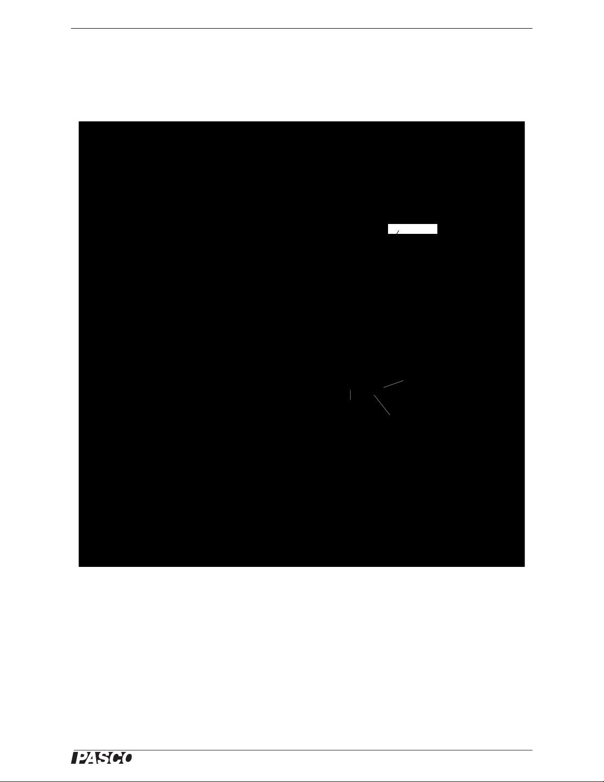
Suspension Bridge Details
Note that the suspension bridge is constructed using the I-beams sideways for the arched part of the bridge.
Because the I-beams bend more in this orientation, they form a curve. The beams used in this manner will take a
set and be permanently bent.
This picture shows the entire bridge structure with three Load Cells attached.
1
Page 2
®
Suspension Bridge Details End Assembly
Half round
Half round
Half round
3
Axle, long
1
1
Straight
connector
2
Road bed
clip
Straight
connector
1
Road
4
4
4
4
Straight
connector
Cord
Cord
3
Axle, long
Cord clip
Half round
Half round
Half round
1
3
4
4
Cord connects to cord clip, goes through
this hole on the edge of the half round,
and then goes up to the suspension beam.
Cord
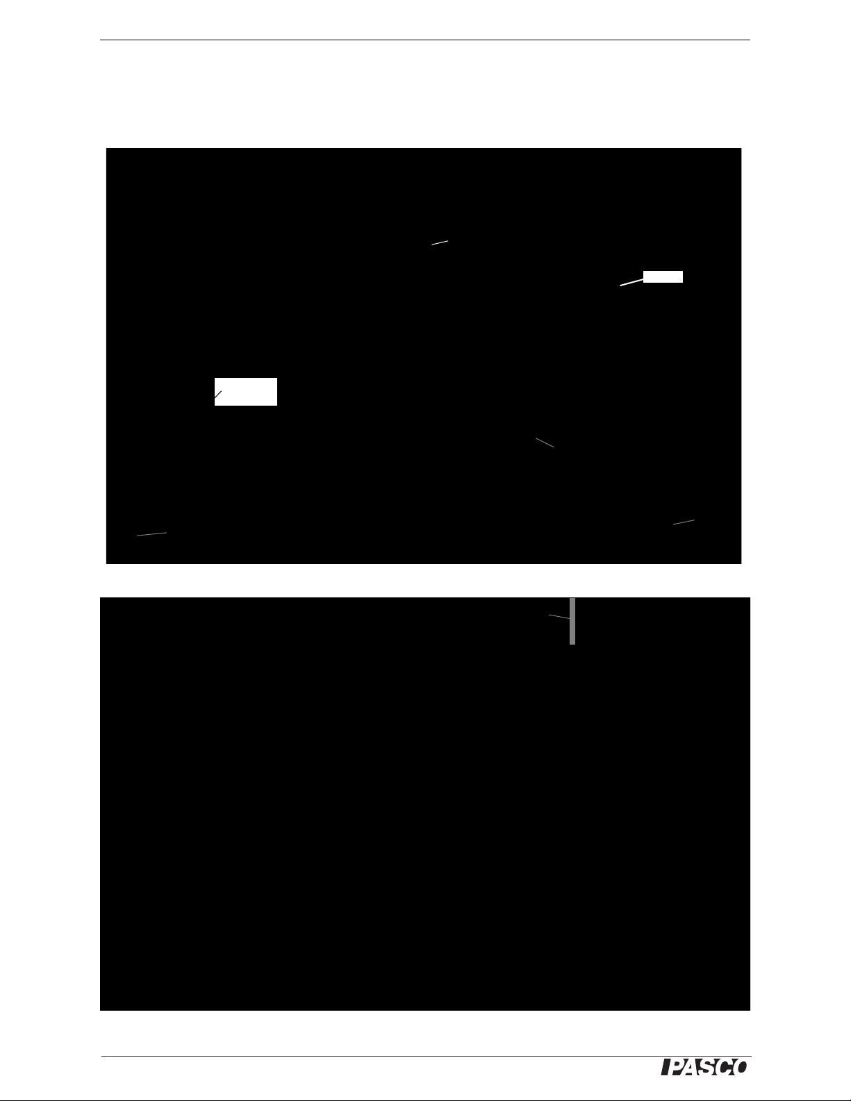
End Assembly
The following pages show details of the construction of the suspension bridg e using parts from th e ME-6 992
Advanced Structures Set and the ME-6991 Bridge Set. This picture shows details of the end assembly.
The next picture shows details of the axle that is the joint between the end assembly and the road bed assembly.
2
Page 3

®
Model No. ME-6992 Tower
Half round
Half round
Half round
Full round
Full
round
Full round
Angle
connector
Angle
connector
1
1
3
4
4
4
4
4
4
2
3
1
4
Middle
section of
road bed
assembly
connects
here.
3
1
Half round
Half round
Tower
The next picture shows details of the road bed assembly where it joins the first tower.
The next picture shows details of the top of the first tower. The suspensions beams are not shown.
3
Page 4

®
Suspension Bridge Details Road Bed Assembly
Midpoint of
middle section
2
2
4
4
Angle connector
Tower connects to
this full round
1
Half round
1
Left half of middle section
Road Bed Assembly
The middle section of the road bed assembly has eight #4 beams on the top of each side, and six #4 beams on the
bottom of each side. The middle of the bottom part of the structure is joined by a #2 beam on both sides. The two
sides are joined by #3 beams. The next picture shows details of one half of the middle section of the road bed
assembly.
Technical Support
For assistance with any PASCO product, contact PASCO at:
Address: PASCO scientific
10101 Foothills Blvd.
Roseville, CA 95747-7100
Phone: 916-786-3800 (worldwide)
800-772-8700 (U.S.)
Fax: (916) 786-7565
Web: www.pasco.com
Email: support@pasco.com
For more information about the Suspension Bridge Details and the latest revision of this Instruction Manual, visit:
www.pasco.com/go?ME-6992
Limited Warranty For a description of the product warranty, see the PASCO catalog.
Copyright The PASCO scientific 012-10999A Suspension Bridge Details Instruction Manual is copyrighted with all rights reserved.
Permission is granted to non-profit educational institutions for reproduction of any part of this manual, providing the reproductions are
used only in their laboratories and classrooms, and are not sold for profit. Reproduction under any other circumstances, without the
written consent of PASCO scientific, is prohibited.
Trademarks PASCO and PASCO scientific are tr ademarks or registered trademarks of PASCO scientific, in the United States and/or
in other countries. All other brands, products, or service names are or may be trademarks or service marks of, and are used to identify, products or services of, their respective owners. For more information visit www.pasco.com/legal.
Patents Pending: The following PASCO products have patents pendng:
ME-6990 Truss Set ME-6991 Bridge Set
ME-6993 Truss Set Members ME-6994 Truss Set Screws
ME-6995 Road Bed Spares ME-6996 Cord Lock Spares
ME-6997 Full Round (XYZ) Connector Spares ME-6998 Axle Spares
ME-6999 Angle Connector Spares PS-2198 Load Cell Amplifier
PS-2199 Load Cell and Amplifier Set PS-2200 100 N Load Cell
PS-2201 5 N Load Cell PS-2205 Dual Load Cell Amplifier
ME-6992 Advanced Structures Set
4
 Loading...