

Page 1

MIC 1161
1/16 DIN MICROBASED LIMIT CONTROLLER
OPERATORS
MANUAL
FORM 3535
EDITION 1
© JAN. 1995
PRICE $10.00
Brand
Page 2

Information in this installation, wiring, and operation manual is subject to change
without notice. One manual is provided with each instrument at the time of shipment. Extra copies are available at the price published on the front cover.
Copyright © January 1995, The Partlow Corporation, all rights reserved. No part
of this publication may be reproduced, transmitted, transcribed or stored in a retrieval system, or translated into any language in any form by any means without
the written permission of the Partlow Corporation.
This is the First Edition of the MIC 1161 manual. It was written and produced
entirely on a desk-top-publishing system. Disk versions are available by written
request to the Partlow Publications Department.
We are glad you decided to open this manual. It is written so that you can take full
advantage of the features of your new MIC 1161 limit controller.
NOTE:
It is strongly recommended that Partlow equipped applications incorporate a high or low limit protective device which
will shut down the equipment at a preset process condition
in order to preclude possible damage to property or products.
!
THE INTERNATIONAL HAZARD SYMBOL IS INSCRIBED ADJACENT TO
THE REAR CONNECTION TERMINALS. IT IS IMPORTANT TO READ
THIS MANUAL BEFORE INSTALLING OR COMMISSIONING THE UNIT.
MIC 1161 Manual
2
Page 3

Table of Contents
Section 1 - General Page
1.1 Product Description 5
Section 2 - Installation & Wiring
2.1 Installation & Wiring 7
2.2 Preparations for Wiring 9
2.3 Input Connections 17
2.4 Output Connections 19
Section 3 - Configuration & Operation
3.1 Operation 21
3.2 Configuration 26
Appendices
A - Glossary of Terms 32
B - Exploded View & Board Layout 36
Figure B-1 Exploded View 36
Figure B-2 CPU PWA 37
Figure B-3 Option PWA DC Output 3 38
C - Hardware Definition Code 39
D - Input Range Codes 41
E - Specifications 43
F - Model Number Hardware Matrix 47
G- Software Reference 48
3 MIC 1161 Manual
Page 4

Figures & Tables
Figure 1-1 Display Illustration 6
Figure 2-1 Panel Cut-Out Dimensions 8
Figure 2-2 Main Dimensions 8
Figure 2-3 Panel Mounting 9
Figure 2-4 Noise Suppression 12
Figure 2-5 Noise Suppression 12
Figure 2-6 Wiring 16
Figure 2-7 AC Power 17
Figure 2-8 Thermocouple Input 17
Figure 2-9 RTD Input 17
Figure 2-10 Volt, mV mADC Input 18
Figure 2-11 Remote Reset Input 18
Figure 2-12 Remote Digital Connections 19
Figure 2-13 Relay Output 1 19
Figure 2-14 Relay Output 2 19
Figure 2-15 Relay Output 3 20
Figure 2-16 mADC Output 3 20
Table 3-1 Enable Mode Configuration Procedures 27
Table 3-2 Program Mode Configuration Procedures 28
Table 3-3 Set-Up Mode Configuration Procedures 30
MIC 1161 Manual
4
Page 5

Product Description 1.1
1.1.1 GENERAL
This instrument is a microprocessor based single loop limit controller, user
configurable to either High Limit type or Low Limit type.
The input is user configurable to directly connect to either thermocouple,
RTD, mVDC, VDC or mADC inputs. The instrument can operate from a
90-264 VAC, 50/60 HZ power supply.
Features include fail safe operation (relay de-energized by the limit exceeded condition), front panel Reset switch, time limit exceeded display
and maximum/minimum tracking of excursions of the process variable.
1.1.2 DISPLAYS
Each instrument is provided with dual displays and status indicators as
shown in Figure 1-1. The upper display displays the value of the process
variable. The lower display displays the setpoint value. Status indication is
as shown in Figure 1-1, page 6.
1.1.3 ALARMS
Alarm indication is standard on all instruments. Up to two alarm outputs
are possible. Alarm type may be set as Process Direct or Reverse (high or
low), Logical Combination of the two alarms and Annunciator Direct or
Reverse. Alarm status is indicated by LED.
1.1.4 PROCESS VARIABLE/SETPOINT VALUE
RE-TRANSMISSION OUTPUT
If the instrument is specified with this option, this output may be scaled over
any desired range and re-transmitted.
5 MIC 1161 Manual
Page 6

FIGURE 1-1
Keys and Indicators
AUTO
RESET
TOP
1 161
OUT EXCEED ALM
MIC 1161 Manual
6
Page 7

Installation and Wiring 2.1
Electrical code requirements and safety standards should be observed and
installation performed by qualified personnel.
The electronic components of the instrument may be removed from the
housing during installation. To remove the components, grip the side
edges of the front panel and pull the instrument forward. During re-installation, the vertically mounted circuit boards should be properly aligned in the
housing.
Ensure that the instrument is correctly orientated. A stop will operate if an
attempt is made to insert the instrument incorrectly.
can be over-ridden with enough force. If in doubt, check orientation
again!
Recommended panel opening sizes are illustrated in Figure 2-1, page 8.
After the opening is properly cut, insert the instrument into the panel opening. Ensure that the panel gasket is not distorted and that the instrument is
positioned squarely against the panel. Slide the mounting clamp into place
on the instrument (see Figure 2-3, page 9) and push it forward until it is
firmly in contact with the rear face of the mounting panel.
CAUTION: This stop
Note: The mounting clamp tongues may engage either on the
sides or the top/bottom of the instrument housing. Therefore, when
installing several instruments side-by-side in one cut out, use the
ratchets on the top/bottom faces.
7 MIC 1161 Manual
Page 8
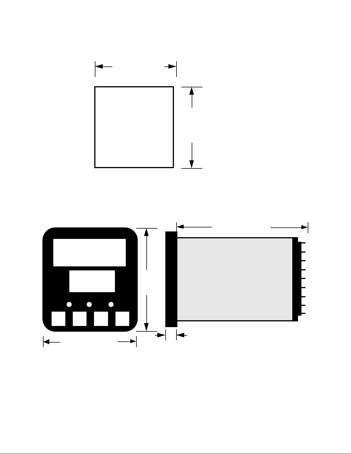
FIGURE 2-1
Panel Cut-Out Dimensions
45 mm +0.5 - 0.0
(1.77" +.024 - .000)
PANEL
CUTOUT
SIZE
FIGURE 2-2
Main Dimensions
45 mm +0.5 - 0.0
(1.77" +.024 - .000)
48 mm (1.89 in.)
110 mm (4.33 in.)
48 mm
(1.89 in)
Side View
10 mm (0.39 in.)
MIC 1161 Manual
8
Page 9
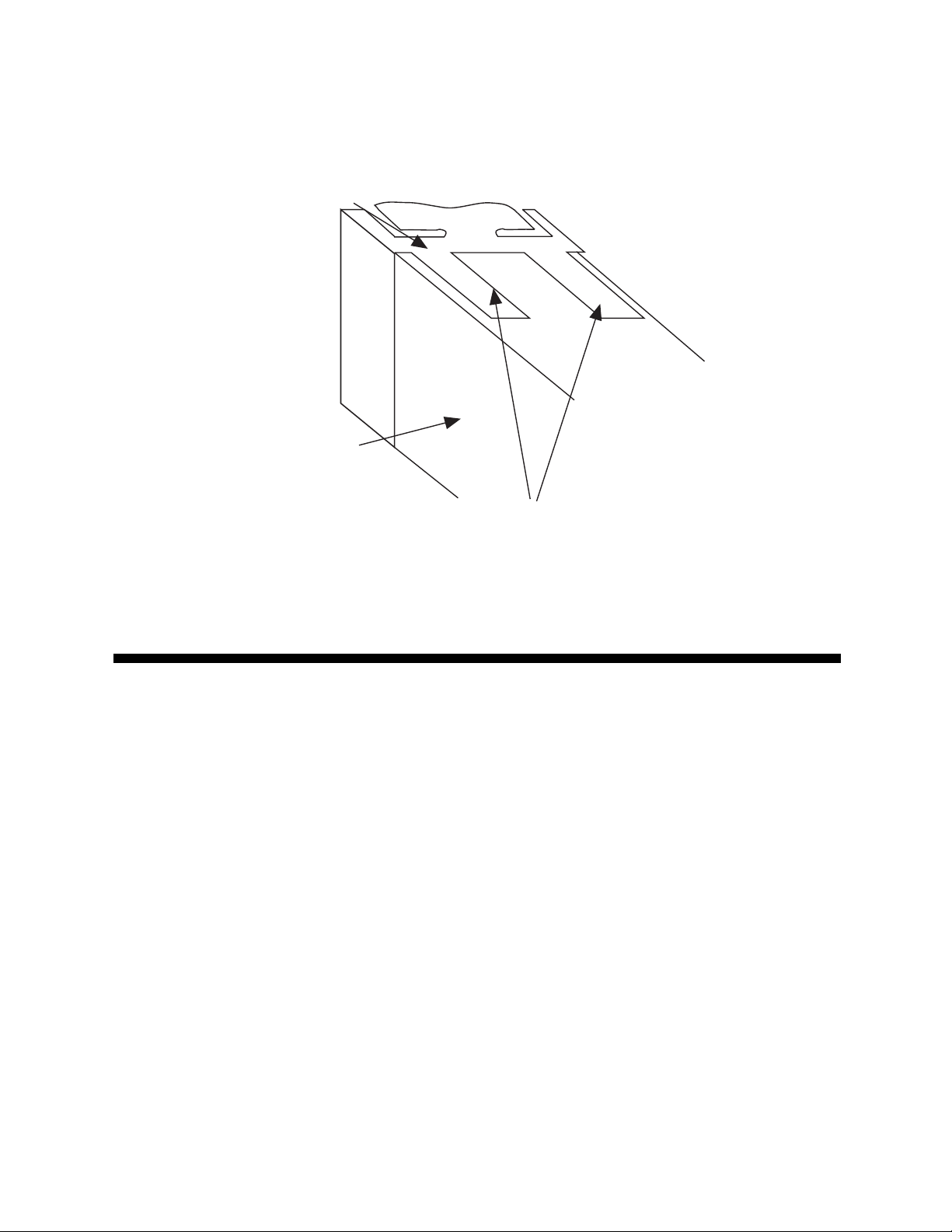
FIGURE 2-3
Panel Mounting the Controller
Mounting Clamp
Controller Housing
Tongues on mounting clamp engage in
ratchet slots on controller housing
Preparation for Wiring 2.2
2.2.1 WIRING GUIDELINES
Electrical noise is a phenomenon typical of industrial environments. The
following are guidelines that must be followed to minimize the effect of
noise upon any instrumentation.
2.2.1.1 INSTALLATION CONSIDERATIONS
Listed below are some of the common sources of electrical noise in the
industrial environment:
• Ignition Transformers
• Arc Welders
• Mechanical contact relay(s)
• Solenoids
9 MIC 1161 Manual
Page 10

Before using any instrument near the device listed, the instructions below
should be followed:
1. If the instrument is to be mounted in the same panel as any of the
listed devices, separate them by the largest distance possible. For
maximum electrical noise reduction, the noise generating devices
should be mounted in a separate enclosure.
2. If possible, eliminate mechanical contact relay(s) and replace with
solid state relays. If a mechanical relay being powered by an
instrument output device cannot be replaced, a solid state relay can
be used to isolate the instrument.
3. A separate isolation transformer to feed only instrumentation should
be considered. The transformer can isolate the instrument from noise
found on the AC power input.
4. If the instrument is being installed on existing equipment, the wiring in
the area should be checked to insure that good wiring practices have
been followed.
2.2.1.2 AC POWER WIRING
Neutral (For 115 VAC)
It is good practice to assure that the AC neutral is at or near ground potential. To verify this, a voltmeter check between neutral and ground should be
done. On the AC range, the reading should not be more than 50 millivolts.
If it is greater than this amount, the secondary of this AC transformer supplying the instrument should be checked by an electrician. A proper neutral
will help ensure maximum performance from the instrument.
2.2.1.3 WIRE ISOLATION
Four voltage levels of input and output wiring may be used with the unit:
• Analog input or output (i.e. thermocouple, RTD, VDC, mVDC, or mADC)
• SPDT Relays
• AC power
The only wires that should run together are those of the same category. If
they need to be run parallel with any of the other lines, maintain a minimum
6 inch space between the wires. If wires must cross each other, do so at
90 degrees. This will minimize the contact with each other and reduces
“cross talk”.
MIC 1161 Manual
10
Page 11

“Cross Talk” is due to the EMF (Electro Magnetic Flux) emitted by a wire as
current passes through it. This EMF can be picked up by other wires running in the same bundle or conduit.
In applications where a High Voltage Transformer is used (i.e. ignition systems) the secondary of the transformer should be isolated from all other
cables.
This instrument has been designed to operate in noisy environments, however, in some cases even with proper wiring it may be necessary to suppress the noise at its source.
2.2.1.4 USE OF SHIELDED CABLE
Shielded cable helps eliminate electrical noise being induced on the wires.
All analog signals should be run with shielded cable. Connection lead
length should be kept as short as possible, keeping the wires protected by
the shielding. The shield should be grounded at one end only. The preferred grounding location is the sensor, transmitter or transducer.
2.2.1.5 NOISE SUPPRESSION AT THE SOURCE
Usually when good wiring practices are followed no further noise protection
is necessary. Sometimes in severe electrical environments, the amount of
noise is so great that it has to be suppressed at the source. Many manufacturers of relays, contactors, etc. supply “surge suppressors” which
mount on the noise source.
For those devices that do not have surge suppressors supplied, RC (resistance-capacitance) networks and/or MOV (metal oxide varistors) may be
added.
Inductive Coils - MOV’s are recommended for transient suppression in
inductive coils connected in parallel and as close as possible to the coil.
See Figure 2-4, page 12. Additional protection may be provided by adding
an RC network across the MOV.
11 MIC 1161 Manual
Page 12
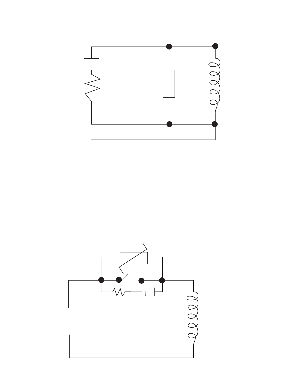
FIGURE 2-4
0.5
mfd
1000V
220
Coil
ohms
115V 1/4W
230V 1W
Contacts - Arcing may occur across contacts when the contact opens and
closes. This results in electrical noise as well as damage to the contacts.
Connecting a RC network properly sized can eliminate this arc.
For circuits up to 3 amps, a combination of a 47 ohm resistor and 0.1
microfarad capacitor (1000 volts) is recommended. For circuits from 3 to 5
amps, connect 2 of these in parallel. See Figure 2-5.
FIGURE 2-5
MIC 1161 Manual
MOV
R C
Inductive
Coil
12
Page 13

2.2.2 SENSOR PLACEMENT (Thermocouple or RTD)
Two wire RTD’s should be used only with lead lengths less than 10 feet.
If the temperature probe is to be subjected to corrosive or abrasive condi-
tions, it should be protected by the appropriate thermowell. The probe
should be positioned to reflect true process temperature:
In liquid media - the most agitated area
In air - the best circulated area
THERMOCOUPLE LEAD RESISTANCE
Thermocouple lead length can affect instrument accuracy since the size
(gauge) and the length of the wire affect lead resistance.
To determine the temperature error resulting from the lead length resistance, use the following equation:
Terr = TLe * L where; TLe = value from appropriate table
L = length of leadwire in thousands of feet
TABLE 1
Temperature error in °C per 1000 feet of leadwire
AWG
NO.
10
12
14
16
18
20
24
Thermocouple T ype:
J
.34
.54
.87
1.37
2.22
3.57
8.78
K
.85
1.34
2.15
3.38
5.50
8.62
21.91
T
.38
.61
.97
1.54
2.50
3.92
9.91
R
1.02
1.65
2.67
4.15
6.76
10.80
27.16
S
1.06
1.65
2.65
4.18
6.82
10.88
27.29
E
.58
.91
1.46
2.30
3.73
5.89
14.83
B
7.00
11.00
17.50
27.75
44.25
70.50
178.25
N
1.47
2.34
3.72
5.91
9.40
14.94
37.80
C
1.26
2.03
3.19
5.05
8.13
12.91
32.64
See next page for Table 2
13 MIC 1161 Manual
Page 14

TABLE 2
Temperature error in °F per 1000 feet of leadwire
AWG
NO.
10
12
14
16
18
20
24
Thermocouple T ype:
J
.61
.97
1.57
2.47
4.00
6.43
15.80
K
1.54
2.41
3.86
6.09
9.90
15.51
39.44
T
.69
1.09
1.75
2.77
4.50
7.06
17.83
R
1.84
2.97
4.81
7.47
12.17
19.43
48.89
S
1.91
2.96
4.76
7.52
12.28
19.59
49.13
E
1.04
1.64
2.63
4.14
6.72
10.61
26.70
B
12.60
19.80
31.50
49.95
79.95
126.90
320.85
N
2.65
4.21
6.69
10.64
10.64
26.89
68.03
C
2.27
3.66
5.74
9.10
9.10
23.24
58.75
Example:
A instrument is to be located in a control room 660 feet away from the process. Using 16 AWG, type J thermocouple, how much error is induced?
Terr = TLe * L
TLe = 2.47 (°F per 1000 ft) from Table 2
Terr = 2.47 (°F/1000 ft) * 660 ft
Terr = 1.6°F
RTD LEAD RESISTANCE
RTD lead length can affect instrument accuracy, since the size (gauge) and
length of the wire affect lead resistance.
To determine the temperature error resulting from the lead length resistance, use the following equation:
Terr = TLe * L where; TLe = value from Table 3 if 3 wire RTD or
Table 4 if 2 wire RTD
L = length of lead wire in thousands of feet
MIC 1161 Manual
14
Page 15

TABLE 3 3 Wire RTD
AWG NO.
TABLE 4 2 Wire RTD
AWG NO.
10
12
14
16
18
20
24
10
12
14
16
18
20
24
Error °C
± 0.04
± 0.07
± 0.10
± 0.16
± 0.26
± 0.41
± 0.65
Error °C
± 5.32
± 9.31
± 13.3
± 21.3
± 34.6
± 54.5
± 86.5
Error °F
± 0.07
± 0.11
± 0.18
± 0.29
± 0.46
± 0.73
± 1.17
Error °F
± 9.31
± 14.6
± 23.9
± 38.6
± 61.2
± 97.1
± 155.6
Example:
An application uses 2000 feet of 18 AWG copper lead wire for a 3 wire RTD
sensor. What is the worst case error due to the leadwire length?
Terr = TLe * L
TLe = ± .46 (°F/1000 ft) from Table 3
Terr = ± .46 (°F/1000 ft) * 2000 ft
Terr = ± 0.92°F
15 MIC 1161 Manual
Page 16

FIGURE 2-6
Wiring Label
OUTPUT 1
-
+
-
N/O
C
Relay
N/C
OUTPUT 3
Relay
N/OCN/C
DC
-
16 17 18
1
2
3
4
+
Top of controller
7
8
9
10
No external
connections
to be made
to these
terminals
L
MAINS (LINE)
SUPPLY
N
INPUT
Linear (mA)
-
+
+
Linear (V/mV)
Thermocouple
RTD
5
6
13 14 15
N/O
C
Relay
OUTPUT 2
N/C
11
12
A
RS485
SERIAL
COMMS.
B
MIC 1161 Manual
16
Page 17

Input Connections 2.3
In general, all wiring connections are made to the instrument after it is installed. Avoid electrical shock. AC power wiring must not be connected to
the source distribution panel until all wiring connection procedures are
completed.
FIGURE 2-7
AC Power
Connect the line voltage, hot and neutral, to terminals 9 and 10 respectively
as illustrated below.
L
9
10
FIGURE 2-8
Thermocouple (T/C) Input
Make thermocouple connections as illustrated below. Connect the positive
leg of the thermocouple to terminal 5 and the negative leg to terminal 4.
-
+
Thermocouple
N
4
5
6
FIGURE 2-9
RTD Input
Make RTD connections as illustrated on page 18. For a three wire RTD,
connect the resistive leg of the RTD to terminal 6 and the common legs to
terminals 4 and 5. For a two wire RTD, connect one leg to terminal 5 and
the other leg to terminal 6 as shown. A jumper wire supplied by the customer must be installed between terminals 4 and 5. Input conditioning
jumper must be positioned correctly (see Appendix B) and Hardware Definition Code must be correct (see Appendix C).
17 MIC 1161 Manual
Page 18

4
5
RTD
6
FIGURE 2-10
Volt, mV Input
Make volt and millivolt connections as shown below. Terminal 5 is positive
and terminal 4 is negative. Input conditioning jumper must be positioned
correctly (see Appendix B) and Hardware Definition Code must be correct
(see Appendix C).
mADC Input
Make mADC connections as shown below. Terminal 4 is positive and terminal 6 is negative. Input conditioning jumper must be positioned correctly
(see Appendix B) and Hardware Definition Code must be correct (see Appendix C).
+
-
+
Linear (mA)
-
Linear (V/mV)
FIGURE 2-11
Remote Reset
Make connections as shown below.
4
5
6
11
12
N.O.
MIC 1161 Manual
18
Page 19

FIGURE 2-12
Remote Digital Communications - RS485
Make digital communication connections as illustrated below.
11
A
RS-485
Seriel
Comms.
12
B
Output Connections 2.4
FIGURE 2-13
Relay Output 1
Connections are made to Output 1 relay as illustrated below. The contacts
are rated at 5 amp resistive, 120/240 VAC.
N/O
C
Relay
1
2
N/O
3
Relay
C
N/C
N/C
FIGURE 2-14
Relay Output 2
Connections are made to Output 2 relay as illustrated below. The contacts
are rated at 2 amp resistive, 120/240 VAC.
13 14 15
19 MIC 1161 Manual
Page 20

FIGURE 2-15
Relay Output 3
Connections are made to Output 3 relay as illustrated below. The contacts
are rated at 2 amp resistive, 120/240 VAC.
Relay
N/OCN/C
16 17 18
FIGURE 2-16
mADC Output 3 (Recorder Output Only)
Make connections for DC output 3 as illustrated below.
DC
-
16 17 18
+
MIC 1161 Manual
20
Page 21

Operation 3.1
3.1.1 POWER UP PROCEDURE
Verify all electrical connections have been properly made before applying
power to the instrument.
During power up, a self-test procedure is initiated during which all LED
segments in the two front panel displays appear and all LED indicators are
ON. When the self-test procedure is complete, the instrument reverts to
normal operation.
Note: There is about a 3 second delay when power is first applied
before the self-test begins.
3.1.2 KEYPAD OPERATION
RESET KEY
This key is used to:
1. Reset the limit condition after the process is within the limit.
2. Acknowledge the exceedence of the limit.
3. Confirm entry in Program mode.
SCROLL KEY
This key is used to:
1. Select a parameter to be viewed or adjusted.
2. Display enabled modes of operation.
3. Display a mode parameter value.
4. Advance display from a parameter value to the next parameter code.
5. With the DOWN key to view the current Hardware Definition Code
setting.
UP KEY
This key is used to:
1. Increase the displayed parameter value.
2. Increase setpoint.
3. With the DOWN key to reset MAX/MIN HOLD and TIME EXCEED.
21 MIC 1161 Manual
Page 22

DOWN KEY
This key is used to:
1. Decrease the displayed parameter value.
2. Decrease setpoint.
3. With the SCROLL key to view the current Hardware Definition Code
setting.
4. With the UP key to reset MAX/MIN HOLD and TIME EXCEED.
3.1.3 DISPLAYS
During normal operation, the upper display shows the value of the process
variable. The lower display shows the setpoint value. If configured in SetUp mode, the upper display can show the setpoint value and the lower
display is blank. During configuration the upper display shows the parameter setting. The lower display shows the parameter code for the currently
selected parameter.
3.1.3.1 DISPLAY SEQUENCE
During normal operating conditions, when the SCROLL key is pressed,
"ULoc" will appear in the lower display and "0" in the upper display. To gain
acess to the Program and Set-Up modes, enter the correct code to "unlock"
accessability to these modes, then press the SCROLL key and "CtrL" will
appear in the display. Press the SCROLL key to the Program and/or SetUp modes.
If any alarms have been programmed and the alarm(s) is/are energized,
the display sequence is as follows: Press the SCROLL key and the Alarm
Status Display, code "ALSt" appears in the lower display. Press the
SCROLL key again and the upper display will then be showing the alarm
status in the following format:
Alarm 1 Status
1 = Energized
Blank = De-energized
Alarm 2 Status
2 = Energized
Blank = De-energized
MIC 1161 Manual
22
Page 23

Pressing the SCROLL key and the display returns to its normal mode.
To gain access to the Program and/or Set-Up modes while an alarm is
active, press the SCROLL key until "ALSt" appears in the lower display.
With "ALSt" in the lower display, press the UP key and "ULoc" appears in
the lower display and "0" in the upper display. Enter the correct code to
unlock, then press the SCROLL key to the Program and/or Set-Up modes.
3.1.3.2 OVER-RANGE/UNDER-RANGE DISPLAY
If the process variable attains a value higher than the input scale maximum
limit, the upper display will show:
If the process variable attains a value lower than the input scale minimum
limit, the upper display will show:
If a break is detected in the sensor circuit, the upper display will show:
23 MIC 1161 Manual
Page 24

3.1.4 FRONT PANEL INDICATORS
OUT Indicates the status of the Limit Relay. When the indicator is
ON, the relay is de-energized and when Off the relay is
energized.
EXCEED This indicator is On when the process variable exceeds the limit
setpoint (above for high limit, below for low limit). The indicator
flashes if the exceedence is not acknowledged (i.e. Reset key
is not pressed). The indicator is on steady if the exceedence
has been acknowledged (i.e. Reset key has been pressed).
Note: This LED action will occur even if the annunciator
output is NOT selected in configuration.
ALM This indicator shows an alarm condition.
S Indicates when in Set-Up mode.
3.1.5 SETPOINT ADJUSTMENT
To adjust the instrument setpoint, proceed as follows:
The setpoint is adjusted in the Set-Up mode. With "SEt" in the lower dis-
play, press the DOWN key, "SP" will appear in the lower display. With "SP"
in the lower display, press the SCROLL key. The current setpoint value will
appear in the upper display. To adjust the setpoint, press the UP or DOWN
key as applicable.
Momentary depression will increment or decrement the setpoint by one unit
in the least significant digit. If the key is held for longer than 1 second, the
least significant digit will change at the rate of 25 units per second. If the
key is held for longer than 10 seconds, the second least significant digit will
change at the rate of 25 units per second. If the key is held for another 10
seconds, the third least significant digit will change at the rate of 25 units
per second.
MIC 1161 Manual
24
Page 25

3.1.6 MAXIMUM/MINIMUM HOLD
A parameter is available that tracks and saves the maximum (high limit) or
minimum (low limit) excursions of the process variable.
This parameter is a read only parameter and is viewed in the Set-Up mode,
display code "HiHd" (maximum hold) and "LoHd" (minimum hold).
To reset this parameter, select the paraemter and with the numeric value in
the upper display, press and hold the UP and DOWN keys. After about 5
seconds, the upper display will indicate ---- for about another 2 seconds,
then change to the current process value.
The value will be held through a supply power down/power up cycle.
3.1.7 TIME EXCEED
This parameter is available to measure the amount of time that the limit is
exceeded.
This parameter is a read only parameter and is viewed in the Set-Up mode,
display code "tLE".
The parameter will time in minutes and seconds from 0 to 99 minutes and
59 seconds. After this time the display will change automatically to indicate
minutes and tens of seconds from 100.0 to 999.5. For times greater than
999.5 the display will be "[HH]".
The value viewed is the cumulative time that the instrument has been out of
limit.
To reset this parameter, select the parameter and with the numeric value in
the upper display, press and hold the UP and DOWN keys. After about 5
seconds, the upper display will indicate ---- for another 2 seconds, then
change to 0.00.
The value will be held through a supply power down/power up cycle.
25 MIC 1161 Manual
Page 26

3.1.8 ANNUNCIATOR
An additional (optional) annunciator output is available. If selected in Program mode (either for USE2 or USE3) the annunciator output operates as
follows:
If the limit is, or has been, exceeded AND the Reset key has NOT been
pressed since the limit was exceeded, then the annunicator output will be
active.
During the condition when the annunciator output is active, the EXCEED
indicator will be flashing.
If the Reset key is pressed while the limit is exceeded, the EXCEED indicator will change to ON steady and the annunciator output is inactive. Subsequently, when the limit is not exceeded, the EXCEED indicator will go off.
3.1.9 REMOTE RESET (optional)
The Remote Reset option allows a dry contact closure to substitute for the
front panel Reset switch. Operation is as follows:
If the option "rrES" (remote reset) is selected then:
A contact closure will simulate the action of the front panel reset
switch.
A contact opening will have no effect.
If the external contacts are left closed, only ONE reset operation will occur.
If the instrument subsequently goes into a state where reset is required
again, the contacts must be opened and closed again. The front panel
Reset switch can still be used to action a reset if required.
Configuration 3.2
All configurable parameters are provided in Tables 3-1 through 3-3 on the
following pages. These tables illustrate the display sequence, parameter
adjustment and factory setting for each step.
Depression of the SCROLL key will cycle the display (if alarms are not
active) to the "Loc" feature where, after entering the correct code, the display cycles through all enabled modes as follows:
MIC 1161 Manual
26
Page 27

CONTROL ---- PROGRAM ---- SETUP
(Ctrl) (Prog) (SEt)
If a mode is not enabled it will be skipped over by the routine.
3.2.1 ENABLE MODE
The Enable mode provides a means of enabling or disabling access to the
Program and Set-Up modes. Also found in the Enable mode is the current
code value for the LOC/ULOC feature. The code may be modified here by
using the UP/DOWN keys when the code is displayed.
If a mode has been disabled, then that mode will not be displayed or available to the user in the Control mode. See Table 3-1 (below) for the Enable
mode procedure.
3.2.2 PROGRAM MODE
The Program mode is used to configure or re-configure the instrument.
The input and output selections are made in the Program mode. All possible parameters are illustrated in Table 3-2 (page 28). Only those parameters that are applicable to the hardware options chosen will be displayed.
3.2.3 SET-UP MODE
The Set-Up mode is used to adjust the setpoint, make alarm settings and
retransmit scaling needed for proper operation of the instrument. See
Table 3-3 (page 30) for the Set-Up mode. Only those parameters that are
applicable will be displayed.
TABLE 3-1 ENABLE MODE
To enter the Enable mode, press and hold the UP and DOWN keys. The
display flashes for about 5 seconds, then returns to a normal display for
about 5 more seconds, then displays "EnAb". Release the keys, the display should show "EPro". Pressing the DOWN key will display the Enable
mode codes in the following sequence:
EPro - - ESEt - - Loc
(Continued on next page)
27 MIC 1161 Manual
Page 28

Pressing the SCROLL key will display the Enable mode codes with the
upper display blank. The next depression of the SCROLL key will add the
Enable code status (ON or OFF) to the upper display. With the Enable
code status displayed, use the UP key to change the status to ON and the
DOWN key to change the status to OFF.
To exit the Enable mode, press the UP key with the Enable code displayed
in the lower display and the upper display blank.
DISPLAY A VAILABLE FACTORY
STEP DESCRIPTION CODE SETTINGS SETTING
1 Program Mode EPro ON/OFF ON
2 Set-Up Mode ESEt ON/OFF ON
3 Lock Loc 0 to 9999 10
TABLE 3-2 PROGRAM MODE
To enter the Program mode, press and release the SCROLL key until
"Prog" is displayed. Use the DOWN key to enter the Program mode. Depress and release the SCROLL key to sequence through the parameters
and their values, alternately showing the parameter code in the lower display with the upper display blank, then the parameter code with the parameter value displayed. Use the UP and DOWN keys to adjust the parameter
values. After adjusting a parameter, the upper display will flash, indicating
that the new setting has yet to be confirmed. When the setting is as required, it may be confirmed by pressing the RESET key and the upper
display stops flashing. After confirming a change, press the SCROLL key
to proceed to the next parameter. Use the DOWN key to advance to the
next parameter when a parameter code is showing in the lower display and
the upper display is blank.
To exit the Program mode, press the UP key whenever a parameter code is
displayed in the lower display and the upper display is blank.
DEFAULT PARAMETER INDICATION
If a parameter value, such as Input Select, was changed while in the Program mode, when returning to the Control mode, a decimal point after each
digit will be lit. This display indicates all Set-Up mode parameters have
been set to their default condition. To clear this condition, enter the Set-Up
mode and make a parameter value change and review each parameter for
its proper setting.
MIC 1161 Manual
28
Page 29

DISPLAY AVAILABLE FACTORY
STEP DESCRIPTION CODE SETTINGS SETTING
1 Input Select inPS See App. D* 1420
2 Limit Action ACt Hi or Lo Hi
3 Alarm 1 Type ALA1 P_hi =Proc High P_hi
nonE=No Alarm
P_Lo=Proc Low
4 Alarm 2 Type ALA2 Same selection as P_hi
ALA1
5 Output 2 Usage USE2 A1_d =Alm 1 Direct A1_d
LA_r =Annunc. Reverse
LA_d=Annunc. Direct
Ad_r =Rev Logic AND
Ad_d=Dir Logic AND
Or_r =Rev Logic OR
Or_d =Dir Logic OR
A2_r =Alm 2 Reverse
A2_d=Alm 2 Direct
A1_r=Alm 1 Reverse
6 Output 3 Usage USE3 A1_d=Alm 1 Direct A1_d
rEcP=Rcdr Out P.V
rEcS=Rcdr Out S.P.
LA_r=Annunc. Reverse
LA_d=Annunc. Direct
Ad_r=Reverse Logic AND
Ad_d=Direct Logic AND
Or_r=Rev Logic OR
Or_d=Dir Logic OR
A2_r=Alm 2 Rev
A2_d=Alm 2 Dir
A1_r=Alm 1 Rev
7 Com Bit Rate CbS 1200, 2400, 4800, 4800
9600
29 MIC 1161 Manual
Page 30

8 Com Address CAd 1 - 32 1
9 CJC Enable CJC EnAb EnAb
diSA
* The Hardware Definition Code and input jumper configuration may need
to be changed. See Appendix B and C.
TABLE 3-3 SET-UP MODE
To enter the Set-Up mode, press and release the SCROLL key until "SEt"
is displayed. Use the DOWN key to enter the Set-Up mode. The "S" LED
should be lit. Depress and release the SCROLL key to sequence through
the parameters and their values, alternately showing the parameter code in
the lower display with the upper display blank, then the parameter code
with the parameter value displayed. Use the UP and DOWN keys to adjust
the parameter values. After adjusting a parameter, depress the SCROLL
key to proceed to the next parameter. Use the DOWN key to advance to
the next parameter when a parameter code is showing in the lower display
and the upper display is blank.
To exit the Set-Up mode, press the UP key whenever a parameter code is
displayed in the lower display and the upper display is blank.
DISPLAY A VAILABLE FACTORY
STEP DESCRIPTION CODE SETTINGS SETTING
1 Limit Setpoint SP ± Span 150**
2 Maximum Hold HiHd Read Only
3 Minimum Hold LoHd Read Only
4 Time Exceeded tLE Read Only
5 Input Filter Filt 0.0 to 100.0 2.0
seconds in .5
second increments
6 Hysteresis HySt 0 to 10% of span, 1
Limit Output expressed in units
MIC 1161 Manual
30
Page 31

DISPLAY A VAILABLE FACTORY
STEP DESCRIPTION CODE SETTINGS SETTING
7 Process Pou -1999 to 9999 Span max.
Out Upper
8 Process PoL -1999 to 9999 Span min.
Out Lower
9 Process High PHA1 ± Span Span Max.
Alarm 1
10 Process Low PLA1 ± Span Span Min.
Alarm 1
11 Process High PHA2 ± Span Span Max.
Alarm 2
12 Process Low PLA2 ± Span Span Min.
Alarm 2
13 Decimal dPoS 0,1,2,3 0
Position (Linear Inputs)
14 Engineering Euu -1999 to 9999 1000
Units Upper
15 Engineering EuL -1999 to 9999 0
Units Lower
16 Comm. Enable CCon 0=Disable 1
1=Enable
17 Display Enable diSP 0=Disable 1
1=Enable
** Setpoint Default - 150 for linear and F ranges, 65.5 for C ranges except
B thermocouple which is 212F and 100C.
31 MIC 1161 Manual
Page 32

Appendix A
Glossary of Terms
Input Filter Time Constant
This parameter is used to filter out any extraneous impulses on the process
variable. This filtered PV is used for all PV-dependent functions (limit,
alarm, etc). The time constant is adjustable from 0.0 seconds (off) to 100.0
seconds, in 0.5 second increments. Default value is 2.0 seconds. Display
code is FiLt.
Hysteresis
This parameter is a switching differential on the non-exceeded side of limit
and is adjustable within the range of 0 to 10.0%, expressed in units. Default value is 1. Display code is HySt.
Process Output Upper Value
This parameter defines the value of the retransmitted output (process variable or setpoint , whichever is applicable) at its maximum value; for example, for a 0-5V output, this value corresponds to 5V. It may be adjusted
within the range -1999 to 9999. The decimal position is always the same
as that for the process variable input. Default value is Input Range Maximum. Display code is Pou.
Note: If this parameter is set to a value less than that for the Process Output Lower Value, the relationship between the process variable/setpoint
value and the retransmission output is reversed.
Process Output Lower Value
This parameter defines the value of the retransmitted output (process variable or setpoint, whichever is applicable) at its minimum value; for example, for a 0-5V output, this value corresponds to 0 V. It may be adjusted
within the range -1999 to 9999. The decimal position is always the same
as that for the process variable input. Default value is Input Range Minimum. Display code is PoL.
Note: If this parameter is set to a value greater than that for the Process
Output Upper Value, the relationship between the process variable/setpoint
value and the retransmission output is reversed.
MIC 1161 Manual
32
Page 33

Process High Alarm 1 Value
This parameter, applicable only when Alarm 1 is selected to be a Process
High alarm, defines the process variable value at or above which Alarm 1
will be active. Its value may be adjusted between Input Range Maximum
and Input Range Minimum. Its default value is Input Range Maximum.
Display code is PHA1.
Process Low Alarm 1 Value
This parameter, applicable only when Alarm 1 is selected to be a Process
Low alarm, defines the process variable value at or below which Alarm 1
will be active. Its value may be adjusted between Input Range Maximum
and Input Range Minimum. Its default value is Input Range Minimum.
Display code is PLA1.
Process High Alarm 2 Value
This parameter, applicable only when Alarm 2 is selected to be a Process
High Alarm, defines the process variable value at or above which Alarm 2
will be active. Its value may be adjusted between Input Range Maximum
and Input Range Minimum. Its default value is Input Range Maximum.
Display code is PHA2.
Process Low Alarm 2 Value
This parameter, applicable only when Alarm 2 is selected to be a Process
Low Alarm, defines the process variable value at or below which Alarm 2
will be active. Its value may be adjusted between Input Range Maximum
and Input Range Minimum. Its default value is Input Range Minimum.
Display code is PLA2.
Logical Combination of Alarms
Two alarms may be combined logically to create an AND/OR situation.
They may be configured for Reverse-acting or Direct-acting. Either Output
2 or Output 3 may be assigned as Logical Outputs.
Example:
Logical OR of Alarm 1 with Alarm 2
Direct-Acting Reverse-Acting
AL-1 OFF, AL-2 OFF: Relay OFF AL-1 OFF, AL-2 OFF: Relay ON
AL-1 ON, AL-2 OFF: Relay ON AL-1 ON, AL-2 OFF: Relay OFF
AL-1 OFF, AL-2 ON: Relay ON AL-1 OFF, AL-2 ON: Relay OFF
AL-1 ON, AL-2 ON: Relay ON AL-1 ON, AL-2 ON: Relay OFF
(Continued on next page)
33 MIC 1161 Manual
Page 34

Logical AND of Alarm 1 with Alarm 2
Direct-Acting Reverse-Acting
AL-1 OFF, AL-2 OFF: Relay OFF AL-1 OFF, AL-2 OFF: Relay ON
AL-1 ON, AL-2 OFF: Relay OFF AL-1 ON, AL-2 OFF: Relay ON
AL-1 OFF, AL-2 ON: Relay OFF AL-1 OFF, AL-2 ON: Relay ON
AL-1 ON, AL-2 ON: Relay ON AL-1 ON, AL-2 ON: Relay OFF
Decimal Point
This parameter, applicable only if a linear input is specified, defines the
position of the decimal point in values for the process variable, setpoint,
alarm levels and retransmission outputs as follows:
Value Decimal Point Position
0 XXXX
1 XXX.X
2 XX.XX
3 X.XXX
The default value is 0. Display code is dPoS.
Engineering Units Upper
This parameter, applicable only if a linear input is specified, defines the
scaled input value when the process variable input is at its maximum value.
It is adjustable between -1999 to 9999. The default value is 1000. This
parameter can be set to a value less than (but not equal to) Engineering
Units Lower, in which case the sense of the input is reversed. Display code
is Euu.
Engineering Units Lower
This parameter, applicable only if a linear input is specified, defines the
scaled input value when the process variable input is at its minimum value.
It is adjustable between -1999 and 9999. The default value is 0. This parameter can be set to a value greater than (but not equal to) Engineering
Units Upper, in which case the sense of the input is reversed. Display code
is EuL.
Maximum Hold
This parameter tracks and saves the maximum excursions of the process
variable, applicable to a High Limit only. This is a Read Only parameter.
Display code is HiHd.
MIC 1161 Manual
34
Page 35

Minimum Hold
This parameter tracks and saves the minimum excursions of the process
variable, applicable to a Low Limit only. This is a Read Only parameter.
Display code is LoHd.
Time Exceeded
This parameter measures and saves the amount of time that the limit is
exceeded. The time is measured and displayed in minutes and seconds
from 0 to 99 minutes and 59 seconds. After this time the display will
change automatically to indicate minutes and tens of seconds from 100.0 to
999.5. For times greater than 999.5, the display "[HH]" will be shown. This
is a Read Only parameter. Display code is tLE.
35 MIC 1161 Manual
Page 36

Appendix B
Exploded View & Board Layout
FIGURE B-1 EXPLODED VIEW
Front Panel (top edge)
Front Panel (top edge)
RS485 Communications/Remote Reset
Option PCB
Power Supply PCB
Output 3 Option PCB
CPU PCB
Output 2 Option PCB
Output 3 Option PCB
CPU PCB
MIC 1161 Manual
Power Supply PCB
Output 2 Option PCB
REAR VIEW OF
UNHOUSED
CONTROLLER
36
Page 37

FIGURE B-2 CPU PWA
JU2
JU1
JU3
Input Conditioning Jumper
JU1
RTD
DC
(mV)
T/C
DC
(mA)
DC
(V)
Output T ype Jumper
JU2
RELAY
JU3
RELAY
37 MIC 1161 Manual
Page 38

FIGURE B-3 OPTION PWA DC OUTPUT 3
JU1
DC
0-10V
DC
0-20mA
JU1
DC
0-5V
DC
4-20mA
MIC 1161 Manual
38
Page 39

Appendix C
Hardware Definition Code
The Hardware Definition Code is used to represent the hardware installed
(input type, Output 2 type, Output 3 type and Options); this must be compatible with the hardware actually installed. It can be accessed, with the
instrument in Program mode, by simultaneously depressing the DOWN and
SCROLL keys while the parameter is displayed in the lower display and the
value in the upper display. The displays will show "XXXX" (where X represents any number) in the upper display and "dEFn" in the lower display,
where:
the first (left-most) digit is input type:
1=RTD/Linear mV
2=Thermocouple
3=Linear DC mA
4=Linear DC V
the second digit is Output 1 type:
1=Relay (Limit Only)
the third digit is Output 2 type:
0=Output 2 not installed
1=Relay (Alarm Only)
the fourth digit is Output 3 type:
0=Output 3 not installed
1=Relay (Alarm only)
3=DC 0-10V (retransmit only)
4=DC 0-20mA (retransmit only)
5=DC 0-5V (retransmit only)
7=DC 4-20mA (retransmit only)
The displayed code may be incremented/decremented using the UP/
DOWN keys as required. The maximum setting available is 4117. For
example, the code for a thermocouple input, Relay Output 1 and Relay
Output 3 would be 2101. When the code is first altered, the code display
will flash, until the desired value is displayed and confirmed by pressing the
RESET key.
39 MIC 1161 Manual
Page 40

While the Hardware Definition Code is displayed, depressing the SCROLL
key will cause the display to change to:
nonE or r485 or rrES
OPtn OPtn OPtn
Where "nonE" indicates the absence of the communications option and the
remote reset option. "r485" indicates the presence of the communications
option. "rrES" indicates the presence of the remote reset option.
NOTE: It is essential that this code is changed whenever there is a change
to the instrument's hardware configuration (change of input type, alarm/
retransmit output etc.). The instrument's software depends upon this code
to ensure that the instrument operates correctly.
To exit from the Hardware Definition Code display, depress the DOWN and
SCROLL keys simultaneously.
MIC 1161 Manual
40
Page 41

Appendix D
Input Range Codes
The input ranges available (selectable via the front panel) are:
For Thermocouple Inputs
INPUT DISPLAYED INPUT DISPLAYED
TYPE RANGE CODE TYPE RANGE CODE
R 0 - 1650°C 1127 K -200 - 760°C 6726
R 32 - 3002°F 1128 K -328 - 1399°F 6727
S 0 - 1649°C 1227 K -200 - 1373°C 6709
S 32 - 3000°F 1228 K -328 - 2503°F 6710
J 0.0 - 205.4°C 1415 L 0.0 - 205.7°C 1815
J 32.0 - 401.7°F 1416 L 32.0 - 402.3°F 1816
J 0 - 450°C 1417 L 0 - 450°C 1817
J 32 - 842°F 1418 L 32 - 842°F 1818
J 0 - 761°C 1419 L 0 - 762°C 1819
J 32 - 1402°F 1420* L 32 - 1404°F 1820
T -200 - 262°C 1525 B 100 - 1824°C 1938
T -328 - 504°F 1526 B 212 - 3315°F 1934
T 0.0 - 260.6°C 1541 N 0 - 1399°C 5371
T 32.0 - 501.1°F 1542 N 32 - 2550°F 5324
*Factory Default
For RTD Inputs
Note: Input conditioning jumper JU1 needs to be changed, see Appendix B.
INPUT DISPLAYED INPUT DISPLAYED
RANGE CODE RANGE CODE
0 - 800°C 7220 0.0 - 100.9°C 2295
32 - 1471°F 7221 32.0 - 213.6°F 2296
32 - 572°F 2229 -200 - 206°C 2297
-101.0 - 100.0°C 2230 -328 - 403°F 2298
-149.8 - 212.0°F 2231 -100.9 - 537.3°C 7222
0 - 300°C 2251 -149.7 - 999.1°F 7223
41 MIC 1161 Manual
Page 42

For DC Inputs
Note: Input conditioning jumper JU1 needs to be changed, see Appendix B.
Also, the Hardware Definition Code for the input type must also be changed,
see Appendix C.
INPUT DISPLAYED INPUT DISPLAYED
RANGE CODE RANGE CODE
0 - 20mA 3413 0 - 5V 4445
4 - 20mA 3414 1 - 5V 4434
0 - 50mV 4443 0 - 10V 4446
10 - 50mV 4499 2 - 10V 4450
MIC 1161 Manual
42
Page 43

Appendix E
Specifications
INPUT SPECIFICATIONS
General
Input Sample Rate: Four per second
Input Resolution: 14 bits approximately
Input Impedance: Greater than 100M ohm resistive
(except for DC mA and V inputs)
Isolation: Universal input isolated from all outputs
except SSR at 240 VAC.
Thermocouple
Types: R, S, J, T, K, L, B and N
Sensor Break Protection: Break detected within 2 seconds. Limit
Relay OFF, alarms operate as if the process
variable has gone over-range.
RTD and DC mV
Type and Connection: Three-wire Pt100 (.00385 ohm/ohm/C)
Lead Compensation: Automatic
Sensor Break Protection: Break detected within 2 seconds. Limit
Relay OFF, alarms operate as if the process
variable has gone under-range.
DC mA and DC V
Scale Range Maximum: -1999 to 9999
Scale Range Minimum: -1999 to 9999
Minimum Span: 1 display LSD
Sensor Break Protection: Applicable to 4-20mA, 1-5V, and 2-10V
ranges only. Break detected within 2
seconds. Limit Relay OFF, alarms operate as
if the process variable has gone under-range.
Remote Reset
Type: Voltage free contact, closure required to reset.
43 MIC 1161 Manual
Page 44

Output Specifications
Limit Switch Output 1
Type: Relay
Contact T ype: Single Pole/Double Throw (SPDT)
Rating: 5A resistive at 120/240V AC
Lifetime: > 100,000 operations at rated voltage/current
Isolation: Inherent
OUTPUT 2 (Alarm or Annunciator)
Type: Relay
Contact T ype: Single Pole/Double Throw (SPDT)
Rating: 2A resistive at 120/240V AC
Lifetime: > 500,000 operations at rated voltage/current
Isolation: Inherent
OUTPUT 3 (Alarm, Annunciator, or Retransmit)
Type: Relay or DC linear (retransmit only)
Relay
Contact T ype: Single Pole/Double Throw (SPDT)
Rating: 2A resistive at 120/240V AC
Lifetime: > 500,000 operations at rated voltage/current
Isolation: Inherent
Retransmit
Resolution: Eight bits in 250ms (10 bits in 1000 ms typical, >10
bits in >1000 ms typical).
Update Rate: 4/sec.
Ranges: 0-20mA, 4-20mA, 0-10V, and 0-5V
Load Impedance: 0-20mA: 500 ohm maximum
4-20mA: 500 ohm maximum
0-10V: 500 ohm minimum
0-5V: 500 ohm minimum
Isolation: Isolated from all other inputs and outputs.
MIC 1161 Manual
44
Page 45

Alarms
Maximum Number: Two "soft" alarms
Maximum # Outputs: Up to 2 outputs can be used for alarm purposes
Comb. of Alarms: Logical ORing or ANDing of alarms to an individual
hardware output is available.
PERFORMANCE
Reference Conditions
Ambient Temperature: 20°C ± 2°C
Relative Humidity: 60-70%
Supply Voltage: 90-264VAC 50Hz ±1%
Source Resistance: <10 ohm for T/C input
Lead Resistance: <0.1 ohm/lead balanced (Pt100)
Common Mode
Rejection: >120dB at 50/60Hz giving negligible effect at up to
264V 50/60Hz
Series Mode
Rejection: >500% of span (at 50/60Hz) causes negligible effect
Operating Conditions
Ambient Temperature: 0 to 55°C
Ambient Temperature
Storage: -20 to 80°C
Temperature Stability: 0.01% of span/°C change in ambient
Relative Humidity: 20 to 95% non-condensing
Supply Voltage: 90-264 VAC 50/60Hz
Source Resistance: 1000 ohm maximum (thermocouple)
Lead Resistance: 50 ohm/lead maximum balanced (Pt100)
Measurement Accuracy
DC Linear Inputs: ± 0.25% of span ± 1 LSD
RTD/
Thermocouple Inputs: ± 0.25% of span ± 1 LSD
Note: Reduced performace with Type B T/C
between 100-600 °C (212-1112°F)
Linearization: Better than ± 0.2°C any point, any 0.1°C range
(± 0.05°C typical). Better than ± 0.5°C any point,
any 1°C range.
45 MIC 1161 Manual
Page 46

Cold Junction
Compensation: Better than ± 0.7°C
ENVIRONMENTAL
EMI Susceptibility: Designed to meet EN50082 Part 2 1992
EMI Emissions: Designed to meet EN50081 Part 2 1994
PHYSICAL
Dimensions: 1/16 DIN front panel (48mm x 48mm) 4.33 inches
deep
Mounting: Plug-in with panel mounting fixing strap.
Panel cut-out 45mm x 45mm.
Terminals: Screw type (combination head)
Power Consumption: Approximately 4 watts
Front Panel Sealing: IP65/NEMA 4
Weight: 8 ounces maximum
Approvals: FM pending
MIC 1161 Manual
46
Page 47

Appendix F
Order Matrix
OUTPUT 1
1 Relay
OUTPUT 2
0 None
1 Relay*
OUTPUT 3
0 None
1 Relay*
3 4-20 mA**
1 1 6 1
OPTIONS
0 None
1 RS-485
2 Remote Reset
SUFFIX
(Blank) None
*For alarm output only
** For retransmission only
47 MIC 1161 Manual
Page 48

Appendix G
Software Record/Reference Sheet
MIC 1161 Manual
48
Page 49

Warranty and Return Statement
These products are sold by The Partlow Corporation (Partlow) under the warranties set forth in the following paragraphs. Such warranties are extended only with respect to a purchase of these products, as new merchandise,
directly from Partlow or from a Partlow distributor, representative or reseller, and are extended only to the first buyer
thereof who purchases them other than for the purpose of resale.
Warranty
These products are warranted to be free from functional defects in materials and workmanship at the time the
products leave the Partlow factory and to conform at that time to the specifications set forth in the relevant Partlow
instruction manual or manuals, sheet or sheets, for such products for a period of three years.
THERE ARE NO EXPRESSED OR IMPLIED WARRANTIES WHICH EXTEND BEYOND THE WARRANTIES
HEREIN AND ABOVE SET FORTH. PARTLOW MAKES NO WARRANTY OF MERCHANTABILITY OR FITNESS
FOR A PARTICULAR PURPOSE WITH RESPECT TO THE PRODUCTS.
Limitations
Partlow shall not be liable for any incidental damages, consequential damages, special damages, or any other
damages, costs or expenses excepting only the cost or expense of repair or replacement as described above.
Products must be installed and maintained in accordance with Partlow instructions. Users are responsible for the
suitability of the products to their application. There is no warranty against damage resulting from corrosion, misapplication, improper specifications or other operating condition beyond our control. Claims against carriers for damage in
transit must be filed by the buyer.
This warranty is void if the purchaser uses non-factory approved replacement parts and supplies or if the purchaser
attempts to repair the product themselves or through a third party without Partlow authorization.
Returns
Partlow’s sole and exclusive obligation and buyer’s sole and exclusive remedy under the above warranty is limited to
repairing or replacing (at Partlow’s option), free of charge, the products which are reported in writing to Partlow at its
main office indicated below.
Partlow is to be advised of return requests during normal business hours and such returns are to include a statement
of the observed deficiency. The buyer shall pre-pay shipping charges for products returned and Partlow or its
representative shall pay for the return of the products to the buyer.
Approved returns should be sent to: PARTLOW CORPORATION
2 CAMPION ROAD
NEW HARTFORD, NY 13413 USA
49 MIC 1161 Manual
Page 50

THE PARTLOW-WEST COMPANY
2 CAMPION ROAD • NEW HARTFORD, NY 13413 USA
1-800-866-6659 • 315-797-2222 • FAX 315-797-0403
 Loading...