

Page 1
1
r
r
/
- 1/8 - 1/4 DIN LIMIT CONTROLLERS
16
CONCISE PRODUCT MANUAL (59333-1)
CAUTION: Installation should be only performed by
technically competent personnel. Local Regulations
regarding electrical installation & safety must be observed.
1. INSTALLATION
The models covered by this manual have three different DIN case sizes (refer to
section 9). Some installation details vary between models. These differences have
been clearly shown.
Note: The functions described in sections 2 thru 8 are common to all models.
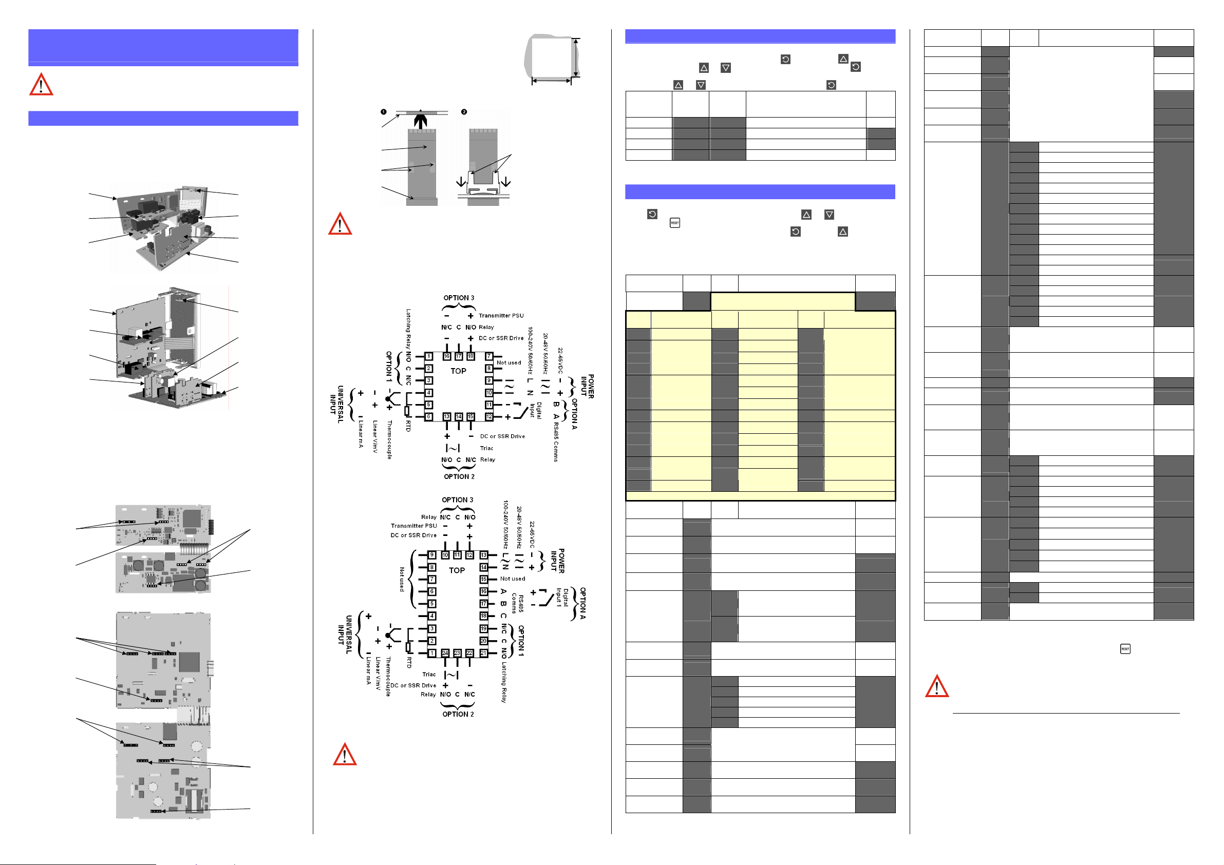
Installing Option Modules
CPU PCB
Option Module 1
(Fixed Limit Relay)
Option Module 2
CPU PCB
Option Module B
(not used on Limit
Controllers)
Option Module 2
Option Module 1
(Fixed Limit Relay)
To access module A, first detach the PSU and CPU boards from the front by lifting
first the upper, and then lower mounting struts. Gently separate the boards.
a. Plug the required option modules into the correct connectors, as shown below.
b. Locate the module tongues in the corresponding slot on the opposite board.
c. Hold the main boards together while relocating back on the mounting struts.
d. Replace the instrument by aligning the CPU and PSU boards with their guides
in the housing, then slowly push the instrument back into position.
Note: Option modules are automatically detected at power up.
Option Module Connectors
Option Slot 1
(Fixed Limit
Option Slot 2
Connecto
Option Slot B
(not used on
Limit Controllers)
Option Slot 2
Connecto
Option Slot 1
(Fixed Limit
Relay)
PL4A
PL4A
Relay)
1
/
Din Size Instruments
16
1
/8 & 1/4 Din Size Instruments
1
/
Din Size Instruments
16
1
/8 & 1/4 Din Size Instruments
Mounting Struts
Option Module A
Option Module 3
PSU PCB
Mounting Struts
Option Module A
Option Module 3
PSU PCB
Option Slot A
Connectors
PL5 & PL6
Option Slot 3
Connector
PL4B
Option Slot A
Connectors
PL5 & PL6
Option Slot 3
Connector
PL4B
Panel-Mounting
The mounting panel must be rigid, and may be up to
6.0mm (0.25inch) thick. Cut-out sizes are:
Cut-Out Dim A Cut-Out Dim B
1
/
& 1/8 Din = 45mm 1/
16
1
/4 Din = 92mm 1/8 & 1/4 Din = 92mm
For n multiple instruments mounted side-by-side, cut-out
A is 48n-4mm (
1
/
& 1/8 Din) or 96n-4mm (1/4 Din)
16
Din = 45mm
16
Mounting Panel
Instrument
Housing
Ratchets
Gasket
B
A
Tolerance +0.5, -0.0mm
Slide mounting clamp
over the instrument
housing towards rear face
of mounting panel until
the tongues engage in
ratchets and instrument is
clamped in position.
Hold instrument firmly in
position (apply pressure
to bezel only)
CAUTION: Do not remove the panel gasket; it is a seal against dust and
moisture.
Rear Terminal Wiring
USE COPPER CONDUCTORS (EXCEPT FOR T/C INPUT)
Single Strand wire gauge: Max 1.2mm (18SWG)
1
/
Din Size Instruments
16
1
/8 & 1/4 Din Size Instruments
2. SELECT MODE
Select mode is used to access the configuration and operation menu functions.
It can be accessed at any time by holding down and pressing .
In select mode, press or to choose the required mode, press to enter.
An unlock code is required to prevent unauthorised entry to Configuration, & Setup
modes. Press or to enter the unlock code, then press to proceed.
Mode Upper
Display
Operator
Set Up
Configuration
Product Info
'(#)* +,$#*
+-#(* +,$#*
$"%&* +,$#*
1%&"* +,$#*
Lower
Display
Description Default
Unlock
Codes
Normal operation None
Tailor settings to the application
Configure the instrument for use
./*
0/*
Check manufacturing information None
Note: The instrument will always return automatically to Operator mode if
there is no key activity for 2 minutes.
3. CONFIGURATION MODE
First select Configuration mode from Select mode (refer to section 2).
Press to scroll through the parameters, then press or to set the required
value. Press to accept the change, otherwise parameter will revert to previous
value. To exit from Configuration mode, hold down and press , to return to
Select mode.
Note: Parameters displayed depends on how instrument has been configured.
Refer to user guide (available from your supplier) for further details.
Parameters marked * are repeated in Setup Mode.
Parameter Lower
Input
Range/Type
Code Input Type &
Range
B: 100 - 1824 ºC
bC
B: 211 - 3315 ºF
bF
C: 0 - 2320 ºC
CC
C: 32 - 4208 ºF
CF
J: –200 - 1200 ºC
JC
J: –328 - 2192 ºF
JF
J: –128.8 - 537.7 ºC
j.C
J: –199.9 - 999.9 ºF
j.F
K: –240 - 1373 ºC
KC
K: –400 - 2503 ºF
KF
K: –128.8 - 537.7 ºC
k.C
K: –199.9 - 999.9 ºF
K.F
L: 0 - 762 ºC
LC
L: 32 - 1403 ºF
LF
Note: Decimal point shown in table indicates temperature resolution of 0.1°
Parameter Lower
Scale Range
Upper Limit
Scale Range
Lower Limit
Decimal point
position
Process Variable
Offset
Upper
Display
Display
1%2#
Code Input Type &
P24C
Upper
Display
Display
)7,
),,*
/=XXXX, .=XXX.X, 0=XX.XX, 9=X.XXX
82"+
'&&+
Adjustment range & Description Default
See following table for possible codes
Code Input Type &
Range
L: 0.0 - 537.7 ºC
L.C
L: 32.0 - 999.9 ºF
L.F
N: 0 - 1399 ºC
NC
N: 32 - 2551 ºF
NF
R: 0 - 1759 ºC
rC
R: 32 - 3198 ºF
rF
S: 0 - 1762 ºC
SC
S: 32 - 3204 ºF
SF
T: –240 - 400 ºC
tC
T: –400 - 752 ºF
tF
T: –128.8 - 400.0 ºC
t.C
T: –199.9 - 752.0 ºF
t.F
PtRh20% vs. 40%:
0 - 1850 ºC
Range
PtRh20% vs 40%:
P24F
32 - 3362 ºF
Pt100: –199 - 800 ºC
PTC
Pt100: –328 - 1472 ºF
PtF
Pt100: –128.8 - 537.7 ºC
Pt.C
Pt100: –199.9 - 999.9 ºF
Pt.F
0 - 20 mA DC
/40/
4 - 20 mA DC
540/
0 - 50 mV DC
/46/
10 - 50 mV DC
./.6/
0 - 5 V DC
/46*
1 - 5 V DC
.46*
0 - 10 V DC
/4./
2 - 10 V DC
04./
Adjustment range & Description Default
Scale Range Lower Limit +100
to Range Maximum
Range Minimum to
Scale Range Upper Limit -100
(non-temperature ranges only)
±Span of controller
(see CAUTION note at end of section)
Value
3$*
Value
Range max
(Lin=1000)
Range min
(Linear=0)
.*
/*
High Limit.
Limit relay is energised when
:1*
process “safe” (PV < Limit Setpoint)
Low Limit.
Limit relay is energised when
,"*
process “safe” (PV > Limit Setpoint)
:1*
Current Setpoint to Scale Range maximum R/max
Scale Range minimum to Current Setpoint R/min
24:1
24,"
8=*
>?%8
%"%=
scaled Range Maximum in display units
Process High Alarm
Process Low Alarm
Deviation Alarm
Band Alarm
No alarm
Scaled Range Minimum to
24:1*
Range Max
Range Min
1 LSD to span from setpoint in display units
+/- Span from setpoint in display units
1 LSD to full span in display units
6*
6*
.*
These diagrams show all possible option combinations. The actual
connections required depends on the exact model and options fitted.
CAUTION: Check information label on housing for correct operating
voltage before connecting supply to Power Input
Fuse: 100 – 240V ac – 1amp anti-surge
24/48V ac/dc – 315mA anti-surge
Note: At first power-up the message !"#" $"%& is displayed, as described in
section 6 of this manual. Access to other menus is denied until configuration
mode is completed
Limit Action
Setpoint Upper
Limit
Setpoint Lower
Limit
Alarm 1Type
High Alarm 1
value*
Low Alarm 1
value*
Band Alarm 1
value*
Dev. Alarm 1
value*
Alarm 1
Hysteresis*
$;<,
+27,
+2,,
?,?.
2@?.
2,?.
>?,.
8?,.
?:A.
Parameter Lower
Display
Alarm 2 Type*
High Alarm 2
value*
Low Alarm 2
value*
Band Alarm 2
value*
Dev. Alarm 2
Value*
Alarm 2
Hysteresis*
Output 2 Usage
Linear Output 2
Range
Retransmit
Output 2 Scale
maximum
Retransmit
Output 3 Scale
minimum
Output 3 Usage
Linear Output 3
Range
Retransmit
Output 3 Scale
maximum
Retransmit
Output 3 Scale
minimum
Display Strategy
Serial
Communications
Protocol
Serial
Communications
Bit Rate
Comms Address
Comms Write
Configuration
Lock Code
Notes: Output 1 is always a Latching Limit Relay output.
If Option Slot A has the Digital Input module fitted, this always functions as a
Remote Reset, duplicating the function of the Reset) key .
As these functions cannot be changed, no Configuration menus are required.
CAUTION: Process Variable Offset can be use to modify the measured
value to compensate for probe errors. Positive values increase the
reading, negative values are subtracted. This parameter is effectively,
a calibration adjustment and MUST be used with care.
There is no front panel indication of when this parameter is in use.
Upper
Adjustment range & Description Default
Display
Value
?,?0* 24,"
2@?0*
2,?0*
>?,0* 6
Options as for alarm 1
Range Max
Range Min
8?,0* 6
?:A0*
Limit Output Relay
Alarm 1, Direct
Alarm 1, Reverse
Alarm 2, Direct
Alarm 2, Reverse
Logical Alarm 1 OR 2, Direct
Logical Alarm 1 OR 2, Reverse
Logical Alarm 1 AND 2, Direct
Logical Alarm 1 AND 2, Reverse
Limit Annunciator, Direct
Limit Annunciator, Reverse
Retransmit Limit SP Output
Retransmit PV Output
0 to 5 V DC output 1
0 to 10 V DC output
2 to 10 V DC output
0 to 20 mA DC output
4 to 20 mA DC output
?B48
)-#2
/4./
C+=0*
#A20*
,Mm#
?B48
?.4)
?048
?04)
')48
')4)
?848
?84)
?%48
?%4)
)-#+
)-#2
/46*
/4./
04./
/40/
540/
-1999 to 9999
)"0:*
(display value at which output
will be maximum)
Range max
-1999 to 9999
)"0,*
C+=9*
#A29*
(display value at which output
will be minimum)
As for output 2
As for output 2
Range min
?B48
/4./
-1999 to 9999
)"9:*
(display value at which output
will be maximum)
Range max
-1999 to 9999
)"9,*
81D(*
2)"#*
>?78*
?88)*
$"=%*
$,"I*
(display value at which output
will be minimum)
=%?>
81+?
?+$E
Mm>%
Mm>=
Mm>"
.G.0*
PV is visible in Operator mode
PV not visible in Operator mode
Modbus with no parity
Modbus with Even Parity
Modbus with Odd Parity
..0*
0.5*
5.F*
G.H*
1.2 kbps
2.4 kbps
4.8 kbps
9.6 kbps
19.2 kbps
ASCII
*1 to 255 (Modbus), 1 to 99 (ASCII)
)4Ww
)4/*
Read/Write
Read only
0 to 9999
Range min
=%?>
Mm>%
5.F
)4Ww
0/
.
.
Page 2
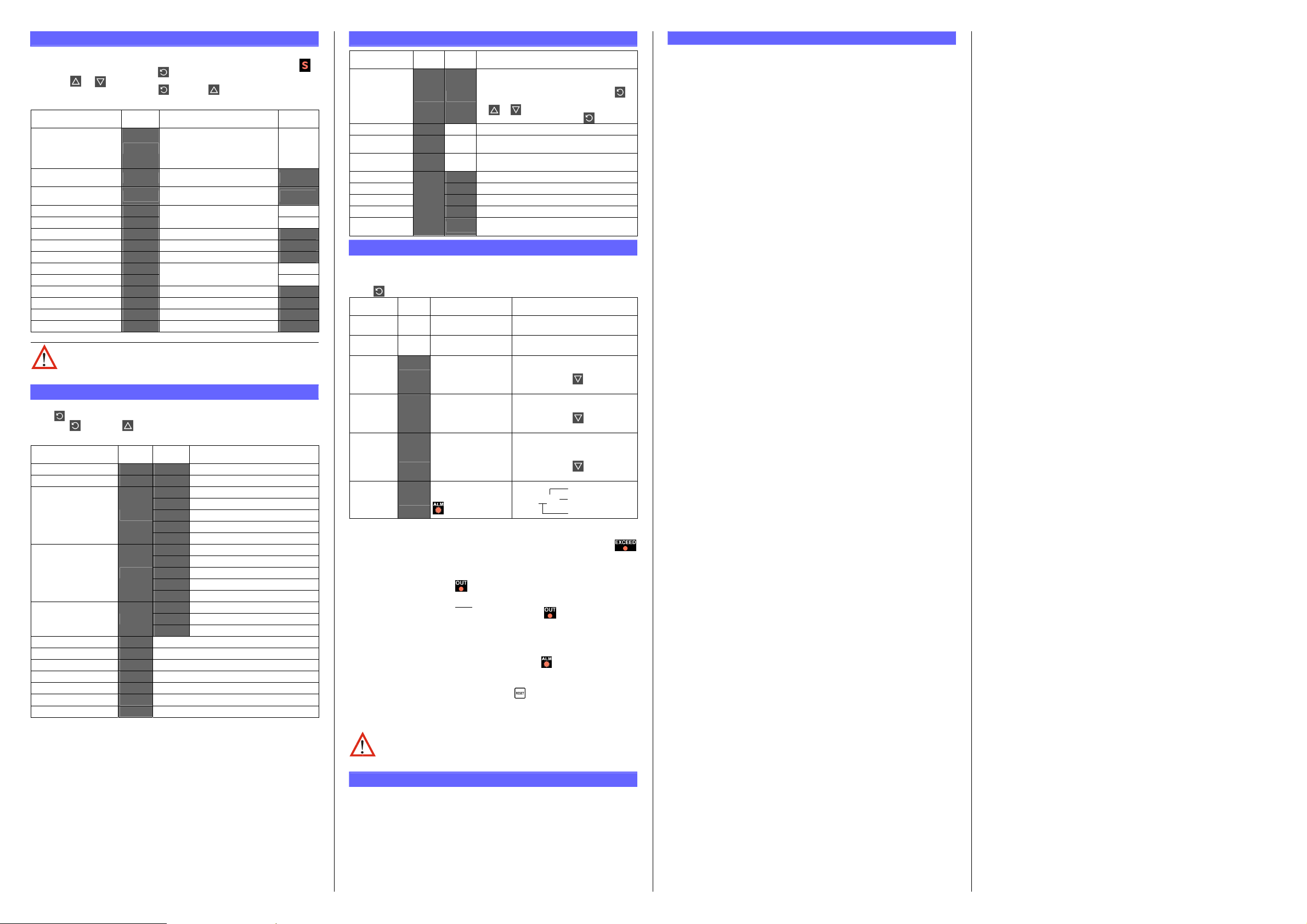
4. SETUP MODE
Note: Configuration must be completed before adjusting Setup parameters.
First select Setup mode from Select mode (refer to section 2). The Setup LED
will light while in Setup mode. Press to scroll through the parameters,
then press or to set the required value.
To exit from Setup mode, hold down and press to return to Select mode.
Note: Parameters displayed depends on how instrument has been configured.
Parameter Lower
Display
Upper Display Adjustment
Range & Description
Default
Value
R/max if
Limit Setpoint value
+2*
Scaled Range Minimum to
scaled Range Maximum
$#),=:1
R/min if
$#),=,"
Limit Hysteresis
Input Filter Time Constant
High Alarm 1 value
Low Alarm 1 value
Deviation Alarm 1 Value
Band Alarm 1 value
Alarm 1 Hysteresis
High Alarm 2 value
Low Alarm 2 value
Deviation Alarm 2 Value
Band Alarm 2 value
Alarm 2 Hysteresis
Setup Lock Code
1 LSD to full span in display units,
:J+#*
&1,#*
2@?.*
2,?.*
8?,.*
>?,.*
?:A.*
2@?0*
2,?0*
8?,0*
>?,0*
?:A0*
+,"I*
on the safe side of the limit SP
OFF or 0.5 to 100.0 secs
(see CAUTION note below)
Scaled Range Minimum to
scaled Range Maximum
±Span from SP in display units
1 LSD to span from setpoint
1 LSD to full span in display units
Scaled Range Minimum to
scaled Range Maximum
±Span from SP in display units
1 LSD to span from setpoint
1 LSD to full span in display units
0 to 9999
0./*
R/max
R/min
R/max
R/min
./*
Note: Operator mode screens follow, without exiting from Setup mode.
CAUTION: An excessively large filter time could significantly delay
detection of a limit condition. Set this value to the minimum required
to remove noise from the process variable
5. PRODUCT INFORMATION MODE
First select Product information mode from Select mode (refer to section 2).
Press to view each parameter. To exit from Product Information mode,
hold down and press to return to Select mode.
Note: These parameters are all read only.
Parameter Lower
Display
Input type
Option 1 type (fixed)
Option 2 module type
fitted
Option 3 module type
fitted
Auxiliary Option A
module type fitted
E%4.* C%1*
'2%.* ),J*
'2%0*
'2%9*
'2%?*
Firmware type
Firmware issue
Product Revision Level
Date of manufacture
8'Mm*
Serial number 1
Serial number 2
Serial number 3
&KL*
EDD*
2<,*
+%.*
+%0*
+%9*
Upper
Description
Display
Universal input
Latching Limit Relay
%"%=*
),J*
++)*
#)1*
,1%*
%"%=*
),J*
++)*
,1%*
8I05*
%"%-*
)5F6*
81!1*
Linear DC voltage / current output
Linear DC voltage / current output
Transmitter power supply
Digital Input for remote reset
No option fitted
Relay output
SSR drive output
Triac output
No option fitted
Relay output
SSR drive output
No option fitted
RS485 communications
Value displayed is firmware type number
Value displayed is firmware issue number
Value displayed is Product Revision level
Manufacturing date code (mmyy)
First four digits of serial number
Middle four digits of serial number
Last four digits of serial number
.*
6*
6*
.*
6*
6*
.*
6. ERROR/FAULT INDICATIONS
Parameter Upper
Display
Lower
Display
Description
Configuration & Setup required. This screen is
Instrument
parameters are in
default conditions
!"#"* $"%&
configuration has been changed. Press to
seen at first turn on, or if hardware
enter the Configuration Mode, next press
or to enter the unlock code number,
then press to proceed
Input Over Range
Input Under
Range
Input Sensor
Break
Option 1 Error
Option 2 Error
Option 3 Error
Option A Error
Option B Error
M::N*
M,,N*
'2=O*
=<<*
Normal
Normal
Normal
'(%.*
'(%0*
'(%9*
'(%?
'(%>*
Process variable input > 5% over-range
Process variable input > 5% under-range
Break detected in process variable input
sensor or wiring
Option 1 module fault
Option 2 module fault
Option 3 module fault
Option A module fault
Option B not used on Limit Controllers
this error is shown if any module is fitted
7. OPERATOR MODE
This mode is entered at power on, or accessed from Select mode (see section 2).
Note: All Configuration mode and Setup mode parameters must be set as
required before starting normal operations.
Press to scroll through the parameters.
Upper
Display
PV Value
Limit SP
Value
Lower
Display Strategy and
Display
Limit SP
Value
(Blank)
When Visible
81+2 = =%?>*
(initial screen)
81+2 = 81+?*
(initial screen)
Description
PV and Limit Setpoint values
Read only
Limit Setpoint value
Read only
Highest PV value since this
High Limit
Hold
:1:8
$#), = :1
parameter was last reset.
To reset, press for 5 seconds,
PPPP
display =
when reset
Lowest PV value since this
Low Limit
Hold
Exceed Time
Value
Active Alarm
Status
,":8
Always available
Format mm.ss to 99.59
#1
(10 sec increments)
Shows
When one or more
alarms are active.
?,+#*
$#), = ,"
then mmm.s
M::N if ≥999.9
ALM indicator
will also flash*
parameter was last reset.
To reset, press for 5 seconds,
PPPP
display =
when reset
Accumulated time of Limit SP
exceed conditions since this
parameter was last reset.
To reset, press for 5 seconds,
display =
PPPP
when reset
L Alarm 2 active
?%0. Alarm 1 active
L Annunciator active
Exceed Condition
An Exceed Condition is when the Process Variable exceeds the Limit Setpoint value
(i.e. PV > SP when set for high limit action, PV < SP for low limit action). The
LED is on during this condition, and is extinguished once it has passed.
Limit Output Function
Limit Output relay(s) de-energise whenever an Exceed condition occurs, causing
the process to shut down. The LED is on when the relay is de-energised.
The relay remains latched off even if the Exceed condition is no longer present.
Only giving a reset instruction (after
the exceed condition has passed) will re-
energise the relay, allowing the process to continue. The LED then turns off.
Limit Annunciator Outputs
An Annunciator output will activate when an Exceed condition occurs, and will
remain active until a reset instruction is received, or the Exceed condition has
passed. Unlike the Limit Output, an Annunciator can be reset even if the Exceed
condition is present. When an Annunciator is active, the LED will flash and the
Alarm Status screen is available.
Resetting Limit Outputs & Annunciators
A reset instruction can be given by pressing the key, via the Digital Input (if
fitted) or via a Comms command if an RS485 Communications module is fitted.
Annunciators will deactivate. Limit Outputs will only re-energise if the Exceed
condition has passed.
CAUTION: Ensure that the cause of the Exceed condition has been
rectified before resetting the Limit Output.
8. SERIAL COMMUNICATIONS
Refer to the full user guide (available from your supplier) for details.
9. SPECIFICATIONS
UNIVERSAL INPUT
Thermocouple
Calibration:
PT100 Calibration:
DC Calibration:
Sampling Rate: 4 per second.
Impedance:
Sensor Break
Detection:
Isolation: Isolated from all outputs (except SSR driver).
Universal input must not be connected to operator accessible
DIGITAL INPUT
Volt-free(or TTL): Open(2 to 24VDC) =No Reset.
Isolation: Reinforced safety isolation from inputs and other outputs.
OUTPUTS
Limit Relay
Contact Type &
Rating:
Lifetime: >100,000 operations at rated voltage/current.
Isolation: Basic Isolation from universal input and SSR outputs.
Alarm Relays
Contact Type &
Rating:
Lifetime: >500,000 operations at rated voltage/current.
Isolation: Basic Isolation from universal input and SSR outputs.
SSR Driver
Drive Capability:
Isolation: Not isolated from universal input or other SSR driver outputs.
Triac
Operating Voltage: 20 to 280Vrms (47 to 63Hz).
Current Rating: 0.01 to 1A (full cycle rms on-state @ 25°C);
Isolation: Reinforced safety isolation from inputs and other outputs.
DC
Resolution: 8 bits in 250mS (10 bits in 1s typical, >10 bits in >1s typical).
Isolation: Reinforced safety isolation from inputs and other outputs.
Transmitter PSU
Power Rating:
Isolation: Reinforced safety isolation from inputs and other outputs.
SERIAL COMMUNICATIONS
Physical: RS485, at 1200, 2400, 4800, 9600 or 19200 bps.
Protocols: Selectable between Modbus and West ASCII.
Isolation: Reinforced safety isolation from all inputs and outputs.
OPERATING CONDITIONS (FOR INDOOR USE)
Ambient
Temperature:
Relative Humidity: 20% to 95% non-condensing.
Supply Voltage and
Power:
ENVIRONMENTAL
Standards: CE, UL, ULC & FM 3545, 1998
EMI: Complies with EN61326 (Susceptibility & Emissions).
Safety
Considerations:
Front Panel Sealing: To IP66 (IP20 behind the panel).
PHYSICAL
Front Bezel Size: 1/
Depth Behind Panel:
Weight: 0.21kg maximum.
±0.1% of full range, ±1LSD (±1°C for Thermocouple CJC).
BS4937, NBS125 & IEC584.
±0.1% of full range, ±1LSD.
BS1904 & DIN43760 (0.00385
Ω/Ω
/°C).
±0.1% of full range, ±1LSD.
>10MΩ resistive, except DC mA (5Ω) and V (47kΩ ).
Thermocouple, RTD, 4 to 20 mA, 2 to 10V and 1 to 5V ranges
only. Limit outputs turn off (goes into Exceed condition), high
alarms activate for thermocouple/RTD sensor break, low
alarms activate for mA/V DC sensor break.
circuits if relay outputs are connected to a hazardous voltage
source. Supplementary insulation or input grounding would
then be required.
Closed(<0.8VDC) = Reset (edge triggered).
Latching limit control relay. Single pole double throw (SPDT);
5A resistive at 120/240VAC. Slot 1 position fixed for this
function, optional function for Slot 2 & 3 relay modules,
Slot 2 or 3 position non-latching alarm relay.
Single pole double throw (SPDT); 2A resistive at 120/240VAC.
SSR drive voltage >10V into 500Ω min.
derates linearly above 40°C to 0.5A @ 80°C.
20 to 28V DC (24V nominal) into 910Ω minimum resistance.
0°C to 55°C (Operating), –20°C to 80°C (Storage).
100 to 240VAC ±10%, 50/60Hz, 7.5VA
(for mains powered versions), or
20 to 48VAC 50/60Hz 7.5VA or 22 to 65VDC 5W
(for low voltage versions).
Complies with EN61010-1 & UL3121.
Pollution Degree 2, Installation Category II.
Din = 48 x 48mm, 1/8 Din = 96 x 48mm,
16
1
/4 Din = 96 x 96mm.
1
/
Din = 110mm, , 1/8 & 1/4 Din = 100mm.
16
 Loading...