


ViX250AE
ViX500AE Servo Drives
User Guide
Part No: 1600.313.02 August, 2003 (For software revision 2.0 onwards)

IMPORTANT INFORMATION FOR USERS
Installation and Operation of Motion Control Equipment
It is important that motion control equipment is installed and operated in such a way that all applicable safety requirements are met. It is your responsibility as an installer to ensure that you identify the relevant safety standards and comply with them; failure to do so may result in damage to equipment and personal injury. In particular, you should study the contents of this user guide carefully before installing or operating the equipment.
The installation, set-up, test and maintenance procedures given in this User Guide should only be carried out by competent personnel trained in the installation of electronic equipment. Such personnel should be aware of the potential electrical and mechanical hazards associated with mains-powered motion control equipment - please see the safety warning below. The individual or group having overall responsibility for this equipment must ensure that operators are adequately trained.
Under no circumstances will the suppliers of the equipment be liable for any incidental, consequential or special damages of any kind whatsoever, including but not limited to lost profits arising from or in any way connected with the use of the equipment or this user guide.
SAFETY WARNING
High-performance motion control equipment is capable of producing rapid movement and very high forces. Unexpected motion may occur especially during the development of controller programs. KEEP WELL CLEAR of any machinery driven by stepper or servo motors. Never touch any part of the equipment while it is in operation.
This product is sold as a motion control component to be installed in a complete system using good engineering practice. Care must be taken to ensure that the product is installed and used in a safe manner according to local safety laws and regulations. In particular, the product must be enclosed such that no part is accessible while power may be applied.
This and other information from Parker-Hannifin Corporation, its subsidiaries and authorised distributors provides product or system options for further investigation by users having technical expertise. Before you select or use any product or system, it is important that you analyse all aspects of your application and review the information concerning the product in the current product catalogue. The user, through its own analysis and testing, is solely responsible for making the final selection of the system and components and assuring that all performance, safety and warning requirements of the application are met.
If the equipment is used in any manner that does not conform to the instructions given in this user guide, then the protection provided by the equipment may be impaired.
The information in this user guide, including any apparatus, methods, techniques, and concepts described herein, are the proprietary property of Parker Electromechanical Division or its licensors, and may not be copied, disclosed, or used for any purpose not expressly authorised by the owner thereof.
Since Parker Electromechanical constantly strives to improve all of its products, we reserve the right to modify equipment and user guides without prior notice. No part of this user guide may be reproduced in any form without the prior consent of Parker Electromechanical Division.
©Electromechanical Division of Parker Hannifin plc, 2003
–All Rights Reserved –

Product Type: ViX250AE, ViX500AE
The above product is in compliance with the requirements of directives
• |
73/23/EEC |
Low Voltage Directive |
• |
93/68/EEC |
CE Marking Directive |
• |
89/336/EEC |
Electromagnetic Compatibility Directive |
Provided the installation requirements described in this user guide are met, and there are no special requirements of the installation and operating environment so that the application may be considered typical, the ViX servo drive series installation will conform to the protection requirements of Council Directive 89/336/EEC as amended by Directive 92/31/EEC on the approximation of the laws of the Member States relating to Electromagnetic Compatibility when operated and maintained as intended.
In assessing the overall compliance of an installation consideration must also be given to the effects of mains harmonics and flicker when interfacing the total supply system to the public low voltage supply system.
In accordance with IEC 61800-3:1997 (Adjustable speed electrical power drive systems) this product is of the restricted sales distribution class which meets the needs of an industrial environment when installed as directed. However, further measures may need to be taken for use of the product in a domestic environment.
Compliance is demonstrated by the application of the following standards:
BS EN 61800-3 |
Adjustable speed electrical power drive systems |
(1997) including |
Part 3. EMC product standard including specific test methods |
Amendment A11 |
|
BS EN 61000-6-2 |
Electromagnetic compatibility – Part 6-2: Generic standards |
(2001) |
Immunity for industrial environments |
BS EN 61000-6-4 |
Electromagnetic compatibility – Part 6-4: Generic standards – |
(2001) |
Emission standard for industrial environments |
BS EN 61010-1 |
Safety requirements for electrical equipment for measurement, |
(1993) including |
control, and laboratory use. Part 1. General requirements |
Amendment A2 |
|
|
|
|
WARNING – Risk of damage and/or personal injury |
The ViX drives described in this user guide contain no user-serviceable parts. Attempting to open the case of any unit, or to replace any internal component, may result in damage to the unit and/or personal injury. This may also void the warranty.

Contact Addresses
For engineering assistance in Europe:
Parker Hannifin plc
Electromechanical
Automation
21 Balena Close Poole, Dorset England, BH17 7DX
Tel: +44 (0)1202-699000
Fax: +44 (0)1202-695750
e-mail: sales.digiplan@parker.com e-mail: support.digiplan@parker.com Website: www.parker-eme.com
For engineering assistance in Italy
Parker Hannifin SpA
Electromechanical Automation
20092 Cinisello Balsamo Milan,
Italy Via Gounod, 1
Tel: +39 02 6601 2478
Fax: +39 02 6601 2808
e-mail: sales.sbc@parker.com Website: www.parker-eme.com
For engineering assistance in Germany
Parker Hannifin GmbH
Electromechanical
Automation
P. O. Box: 77607-1720
Robert-Bosch-Str. 22 D-77656 Offenburg, Germany Tel: +49 (0)781 509-0
Fax: +49 (0)781 509-176
e-mail: sales.hauser@parker.com e-mail: techhelp_emd_OG@parker.com Website: www.parker-eme.com
For engineering assistance in the U.S.:
Parker Hannifin Corporation
Electromechanical Automation
5500 Business Park Drive, Suite D Rohnert Park
CA 94928 USA
Tel: (800) 358-9070
Fax: (707) 584-3793
FaxBack System: (800) 936-6939 e-mail: emn_support@parker.com Website: www.parkermotion.com
Symbols used, have the following meanings:
Caution - Refer to the
accompanying documentation
Protective conductor terminal

|
CONTENTS |
i |
|
Contents |
|
1. |
Introduction............................................................................................................. |
1 |
2. |
Mechanical Installation ........................................................................................... |
5 |
3. |
Electrical Installation............................................................................................... |
9 |
4. |
Control of ViX Drives .............................................................................................. |
51 |
5. |
EASI-V Software .................................................................................................... |
71 |
6. |
Command Reference ............................................................................................. |
87 |
7. |
ViX Maintenance and Troubleshooting .................................................................. |
107 |
8. |
Hardware Reference .............................................................................................. |
113 |
Appendix A .................................................................................................................. |
117 |
|
Appendix B .................................................................................................................. |
119 |
|
Index............................................................................................................................ |
123 |
|
The ViX250AE/500AE Intelligent Digital Servo Drive is UL-Recognised under file
E194158. This means it may be incorporated into end-user products that may be eligible for UL Listing, Classification or Certification.
User Guide Issue Change Summary
This user guide, version 1600.313.02, is the second version of the ViX250AE/ViX500AE Digital Servo Drive.

ii VIX AE SERVO DRIVE USER GUIDE
Latest Changes Sheet
This page lists important changes occurring immediately before publication or between issue updates:
1. INTRODUCTION 1
1. Introduction
Product Description
Available in two power ranges, these digital servos use field-oriented control technology to give enhanced dynamic performance with improved efficiency. Housed within an extremely compact case, the drives are suitable for either direct panel or DIN rail mounting.
Using full PWM control with sinusoidal commutation, the two versions of power stage can have continuous current ratings of 2.5A and 5A at motor bus voltages up to 80V. Having a choice of resolver or encoder feedback, the drives may be used with a wide range of
3-phase servo motors of different pole counts.
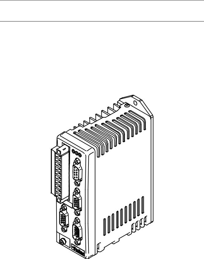
Figure 1-1. ViX250/ViX500 Digital Servo Drive

2 VIX AE SERVO DRIVE USER GUIDE
Product Variants
Digital servo drives are available in two power versions, with resolver or encoder feedback. Table 1-1 lists the possible combinations:
Product Code |
Description |
ViX250AE |
250VA Servo with encoder/resolver feedback |
|
|
ViX500AE |
500VA Servo with encoder/resolver feedback |
|
|
Table 1-1. ViX250/ViX500 Digital Servo Drive Options
Product Features
Protection Circuits |
Function Indicators |
|
Motor short circuits |
Drive Status/Feedback Fault (HV/FB) |
|
Over-voltage |
Drive Fault (DF) |
|
Under-voltage |
|
|
Drive/motor Over-temperature |
|
|
24V reverse supply protection |
|
|
Commutation encoder fault |
|
|
Resolver fault |
|
|
I2t protection |
|
|
|
Outputs and Inputs |
|
|
1 |
Brake input |
|
1 |
Brake output |
|
1 |
Analogue monitor output |
|
|
|

1. INTRODUCTION 3
Fit Kits
Two fit kits are available for ViX drives:
1.VIX-KIT required if you do not purchase motor cables
2.VIX-KIT-NFB required if you do purchase motor cables
VIX-KIT
Part Number |
Quantity |
Description |
1650.937.01 |
1 |
Information |
|
|
sheet |
5004.023 |
1 |
plastic bag |
5006.211 |
1 |
Product label |
0405.811 |
1 |
10-way Flange |
|
|
plug strip |
|
|
|
0405.961 |
1 |
9-way D-type |
|
|
plug |
0405.962 |
2 |
15-way HD |
|
|
D-type plug |
0405.963 |
1 |
15-way HD |
|
|
D-type socket |
0409.530 |
4 |
9-way D-type |
|
|
cover |
0313.020 |
1 |
H8FE1115NC |
|
|
ferrite sleeve |
4005.218 |
1 |
3:1 heatshrink |
|
|
19mm diam. |
4216.101 |
1 |
Closed P-clip |
|
|
9mm ID |
4216.102 |
1 |
Closed P-clip |
|
|
10.7mm ID |
4216.103 |
1 |
Closed P-clip |
|
|
12.3mm ID |
VIX-KIT-NFB
Part Number |
Quantity |
Description |
1650.937.01 |
1 |
Information |
|
|
sheet |
5004.023 |
1 |
plastic bag |
5006.211 |
1 |
Product label |
0405.811 |
1 |
10-way |
|
|
Flange plug |
|
|
strip |
0405.961 |
1 |
9-way D-type |
|
|
plug |
0405.962 |
1 |
15-way HD |
|
|
D-type plug |
0405.963 |
1 |
15-way HD |
|
|
D-type socket |
0409.530 |
3 |
9-way D-type |
|
|
cover |
4 VIX AE SERVO DRIVE USER GUIDE
Further Information
This user guide contains all the necessary information for the effective use of this drive. However, to gain a more in-depth understanding of drive applications and motion control, consider attending one of our world-wide Customer Specific Training Workshops.
Examples of previous courses that have proved to be of benefit include:
Use and programming of the DIN rail H & L series drives
PDFX training
Using the 6K controller
EASI Tools programming
Mechanical product training for ET/ER, XR and HPLA

2. MECHANICAL INSTALLATION 5
2. Mechanical Installation
Installation Requirements
Environment
ViX drives operate in a temperature range of 0° to 40°C with natural convection, or 50°C Max with forced-air cooling (see Hardware Reference), at normal levels of humidity (5-95% non-condensing). The drives can tolerate atmospheric pollution degree 2, which means only dry, non-conductive pollution is acceptable.
Drive Cooling
Cooling of all drive types is by natural convection up to 40°C. To assist cooling, drives should be installed vertically in an area where there is at least a 50mm (minimum) air gap above and below the package and a 10mm (minimum) gap either side. Avoid mounting heat-producing equipment directly below a drive.
Installers must ensure that the air temperature entering the drive or rising up to the drive is within the ambient temperature restrictions. Under normal use the air temperature leaving the drive and heatsink may be 25°C above ambient.
In the final installation, check that the ambient temperature specification of 40°C Max
(without forced air cooling) is not exceeded directly below the top-most drives and that any circulating air flow is not being blocked from reaching the drives. For cabinet cooling calculations, allow 20W per drive.
6 VIX AE SERVO DRIVE USER GUIDE
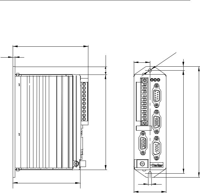
Drive Dimensions
ViX250 and ViX500 drives share the same dimensions, shown in Figure 2-1.
98.5 (with connector)
3 |
10.1 |
|
|
|
124.7 |
|
88,1 |
21 |
4,5 |
|
|
X1 |
HVSTFB |
|
|
|
X3 |
|
X4 |
X2
X5
4,5 |
42 |
Figure 2-1. ViX250 & ViX500 Dimensions
5
135 |
145 |
2. MECHANICAL INSTALLATION 7
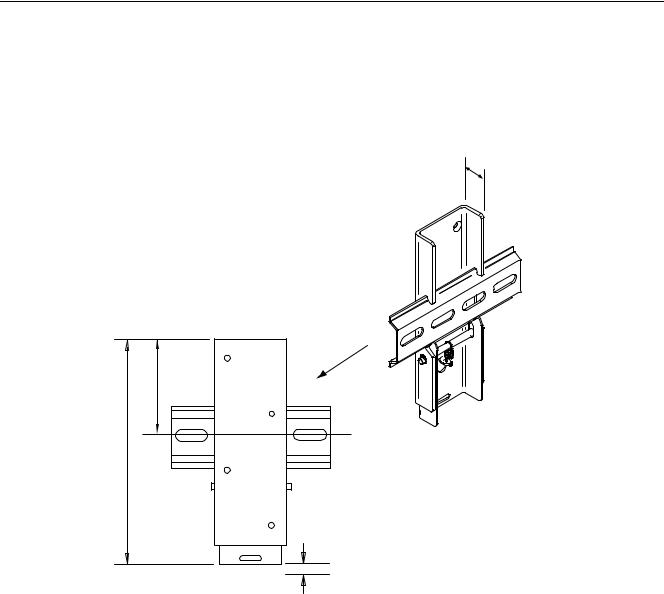
Drive Mounting Options
If you require a DIN-Rail mounting ViX drive use the DIN-Rail clip adapter bracket shown in Figure 2-2.
131.2mm
16mm
57.2mm
Viewed from the back of the DIN rail
Allow 10mm for release
Figure 2-2. DIN-Rail Adapter Bracket
Remove the panel mounting plate from the back of the drive and attach the bracket to the back of the drive using the screws provided. The drive and bracket can now be fixed to a
DIN rail by hooking the top of the bracket over the top of the DIN rail and gently pushing the drive forward to engage the lower section of the bracket. Remove the bracket by inserting a flat bladed screwdriver into the release slot to pull down the bottom of the bracket, releasing it from the DIN rail.
Thermal Limitations
If you are using DIN rail mounting with natural convection airflow cooling and the drive is working under continuous load, the maximum continuous output torque should be de-rated by 10%. For example, using the drive for reel tensioning rather than point-to-point applications may require torque de-rating when using DIN rail mounting.

8 VIX AE SERVO DRIVE USER GUIDE
Motor Mounting Mechanical Considerations
Keep motors securely fixed in position at all times. Do not test a motor/drive combination without first securing the motor – see the Safety Warning at the front of this user guide.
CAUTION – risk of equipment damage
Do not back drive the motor, that is use the motor in an application that causes mechanical rotation of the motor shaft in a manner uncontrolled by the drive.
Back driving the motor at high speed may damage the drive.

3. ELECTRICAL INSTALLATION 9
3. Electrical Installation
Installation Safety Requirements
ViX drives meet the requirements of both the European LVD & EMC directives when installed according to the instructions given within this section. It is recommended the drive be installed in an enclosure to protect it from atmospheric contaminants and to prevent operator access while it has power applied. Metal equipment cabinets are ideally suited for housing the equipment since they can provide operator protection, EMC screening, and can be fitted with interlocks arranged to remove all hazardous motor and drive power when the cabinet door is opened. Do not arrange interlocks to open circuit the motor phase connections while the system is still powered, as this could cause damage to the drive.
Precautions
During installation, take the normal precautions against damage caused by electrostatic discharges. Wear earth wrist straps. A switch or circuit breaker must be included in the installation, which must be clearly marked as the disconnecting device and should be within easy reach of the machine operator.
Cabinet Installation
To produce an EMC and LVD compliant installation we recommend that drives are mounted within a steel equipment cabinet. This form of enclosure is not essential to achieving EMC compliance, but does offer the benefits of operator protection and reduces the contamination of the equipment from industrial processes.
A steel equipment cabinet will screen radiated emissions provided all panels are bonded to a central earth point. Separate earth circuits are commonly used within equipment cabinets to minimise the interaction between independent circuits. A circuit switching large currents and sharing a common earth return with another low level signal circuit could conduct electrical noise into the low level circuit, thereby possibly interfering with its operation. For this reason so called ‘dirty earth’ and ‘clean earth’ circuits may be formed within the same cabinet, but all such circuits will eventually need to be returned to the cabinet’s main star earth point.
Mount the individual drives and EMC filter on a metal earth plane. The earth plane will have its own individual star point earth which should be hard wired (using an insulated copper conductor) back to the cabinet’s ‘clean earth’ connection point.
LVD - Low voltage directive
EMC – Electro Magnetic Compatibility directive
10 VIX AE SERVO DRIVE USER GUIDE
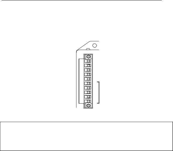
Power Supply Connections
Power drives from a DC supply derived from an isolating transformer or a DC power supply (See Power Supply Options later in this section).
Note: Pin 10 is at the top of the connector X1 and pin 1 at the bottom.
Power & motor X1 |
|
||
10-way |
10 |
+HV |
|
connector |
|||
9 |
-HV |
||
|
|||
|
8 |
PE |
|
|
7 |
+24V |
|
|
6 |
0V (GND 24v DC) |
|
|
5 |
|
|
|
4 |
MOTOR |
|
|
3 |
||
|
CONNECTIONS |
||
|
2 |
|
|
|
1 |
|
|
Figure 3-1. X1 Power Connections
WARNING – Possible drive damage
If you use Parker XL Series stepper drives do not attempt to use any power wiring harness taken from an XL drive. Although the same mating connector is used for both an XL and a ViX, the ViX wiring is the reverse of the XL and the wrong wiring connection will damage the drive.
Mating connector type is: Wieland type number 8213B/ . This connector is available in two forms:
1.Part number 25.323.4053.0 (Parker part number 0405.811)
2.UL marked version with part number 25.323.1053.0

3. ELECTRICAL INSTALLATION 11
Supply Requirements
Power the ViX drives from DC supplies as specified below:
Volts
Drive Type |
DC Supply Voltage |
|
between DC+ and DC- |
ViX500 |
48V to 80V (recommended) |
ViX250 |
24V to 80V |
Table 3-1. Drive Supply Voltages
WARNING
The drive HV supply input is not reverse polarity protected.
Reverse polarity connections will damage the drive.
Current and Capacitance
A supply must have a minimum amount of capacitance to support a drive at peak power draw.
Drive Type |
DC Supply Current |
Supply Capacitance |
ViX500 |
6.3A RMS |
6600 F |
ViX250 |
2.5A RMS |
3300 F |
Table 3-2. Drive Supply Currents
+24V Requirements
Both drive types require a +24V controller and logic supply. The supply to each drive should be fitted with a time-delay fuse, rated at 3A. Note: The +24V supply used must meet the voltage requirement specification of +24V DC +10% -15%, ripple <1V p-p.
The supply may also be required for an encoder and motor brake.
Absolute voltage range |
20 to 27V |
Nominal drive current |
250mA (excluding encoder & brake) |
Extra encoder current |
150mA |
Extra brake current |
500mA |
Safety Earth Requirements
Earth the drive using the earth pin on X1 (pin 8). Also earth the power 0V connector on pin 9.

12 VIX AE SERVO DRIVE USER GUIDE
Power Supply Options
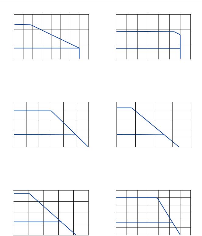
Using the previous section, estimate the power required for a single drive or for a group of drives. A set of torque curves (Figure 3-2) for various motor/drive combinations can be used for calculating an applications likely power requirements.
A single axis using a ViX250, or possibly a lightly loaded dual-axis application may be powered using an XL-PSU. This switching supply has a power rating of 250W and can supply 3.1A continuous (7.5A peak, depending on supply volts and 24V loading) which could be used for BE230D medium speed applications.
Higher torque/current requirements will need to use the ViX500 drive and a high current linear power supply, such as the PL1100. Further power supply information is given in
Appendix A.
3. ELECTRICAL INSTALLATION 13
Nm ViX250 with BE230D motor |
Nm ViX500 with BE163F motor |
1.5 |
|
1.5 |
1.0 |
|
1.0 |
|
PEAK |
|
0.5 |
|
0.5 |
|
CONT. |
|
0 |
|
0 |
0 |
1000 |
1500 2000 2500 3000 3500 4000 4500 |
|
|
rpm |
|
PEAK |
|
|
|
|
|
|
|
CONT. |
|
|
|
|
|
|
0 |
1000 |
2000 |
3000 |
4000 |
5000 |
6000 |
7000 |
|
|
|
rpm |
|
|
|
|
Nm ViX500 with BE231G motor |
Nm ViX500 with BE341G motor |
2.5 |
|
|
|
|
|
5.0 |
2.0 |
PEAK |
|
|
|
4.0 |
|
|
|
|
|
|
||
1.5 |
|
|
|
|
|
3.0 |
1.0 |
|
|
|
|
|
2.0 |
0.5 |
CONT. |
|
|
|
1.0 |
|
|
|
|
|
|
||
0 |
|
|
|
|
|
0 |
0 |
1000 |
2000 |
3000 |
4000 |
5000 |
6000 |
|
|
|
rpm |
|
|
|
|
PEAK |
|
|
|
|
CONT. |
|
|
|
0 |
1000 |
1500 |
2000 |
2500 |
|
|
rpm |
|
|
Nm |
ViX500 with SMB60-30 motor* |
|
|||
4 |
|
|
|
|
|
3 |
PEAK |
|
|
|
|
|
|
|
|
||
2 |
|
|
|
|
|
1 |
CONT. |
|
|
|
|
|
|
|
|
||
0 |
|
|
|
|
|
0 |
1000 |
2000 |
3000 |
4000 |
5000 |
|
|
|
rpm |
|
|
Nm |
ViX500 with SMB82-25 motor* |
|
|||||
6 |
|
|
|
|
|
|
|
5 |
PEAK |
|
|
|
|
|
|
4 |
|
|
|
|
|
||
|
|
|
|
|
|
|
|
3 |
|
|
|
|
|
|
|
2 |
|
|
|
|
|
|
|
1 |
CONT. |
|
|
|
|
|
|
|
|
|
|
|
|
|
|
0 |
|
|
|
|
|
|
|
0 |
500 |
1000 |
1500 |
2000 |
2500 |
3000 |
3500 |
|
|
|
rpm |
|
|
|
|
Figure 3-2. Motor Torque/Speed Characteristics
14 VIX AE SERVO DRIVE USER GUIDE
XL-PSU Power Supply
The XL-PSU is a 250W, power factor corrected, switched mode power supply. Designed for direct operation from world wide single phase AC input voltages, the supply is capable of powering up to two ViX250 drives (see note 1) without the need for an EMC mains input filter (see note 2). The use of the XL-PSU offers the following benefits:
•Auto-adapts to supplies between 95 and 264V AC
•No external EMC filter required
•Compact size
•Built-in power dump switch
•Built-in +24V DC supply
Note 1: Check the application’s power requirements from the torque/speed curve of the motor used.
Note 2: For drives with up to 30 metre motor leads.
For full installation instructions see the XL Power Supply leaflet 1600.300.XX.
3. ELECTRICAL INSTALLATION 15
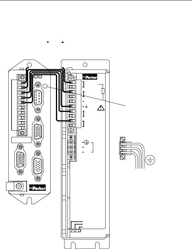
XL-PSU Supply/Drive Connections
When used to supply up to two drives the power supply can be wired as shown in Figure 3-3.
|
10 mm |
|
Mininum spacing |
||||
|
|
between drives & PSU |
|||||
|
|
|
|
|
|
||
|
|
|
|
|
|
|
|
|
|
|
|
|
|
|
|
|
|
|
|
|
|
|
|
|
|
|
|
|
|
|
|
HV STFB |
|
X1 |
|
10 |
1 |
X3 |
+DC (80V) |
|
-DC |
|
EXT. BRAKING RES. |
+24V
X4
GND
10
1
P1
X2 |
N INPUT |
|
MAINS |
X5 |
L |
110V-230V~ |
|
|
50/60 Hz |
|
250VA |
P2
XL
Power
Supply
Unit
If the supply is positioned this side of the drive avoid blocking access to D-type X3
P2 mating socket
The XL_PSU must be securely earthed
L N EARTH (GND.)
HV STATUS
BRAKING RES.
24V STATUS
Figure 3-3. XL Power Supply and Drive Connections

16 VIX AE SERVO DRIVE USER GUIDE
XL-PSU Mounting Information
Mount the supply vertically, near the drives it will supply. Both the top 4.5mm diameter fixing hole and the bottom two 4.5mm width fixing slots should be used.
Allow a minimum free space of 50mm both below and above its case and 10mm free space on both sides.
Do not mount the supply above or close to other products that generate a significant amount of heat by radiation or convection.

3. ELECTRICAL INSTALLATION 17
PL1100 Power Supply
General Description
The PL1100 is a linear power supply with a rated output of 1120W (80V/14A) for use with
ViX and XL series drives. The supply requires a suitably rated transformer supplying 50V AC RMS for the HV and 20V AC RMS for the +24V DC. The use of the PL1100 offers the following benefits:
•Provides 80V HV and +24V DC output
•Single or three phase operation
•Built-in power dump switch
•Integral fusing
Figure 3-4 shows the PL1100 output wiring for two ViX drives. This illustrates how to route the main HV supply separately to each drive. The lower current requirements of the +24V logic/brake supply can allow the wiring to be linked between drives.
For full installation instructions see the PL1100 Power Supply leaflet 1600.323.XX.
In Figure 3-4 the drives are wired individually to the PL1100, alternative daisy chain wiring can be used.
CAUTION
Risk of electric shock.
High voltage remains on terminals after power is removed.
Allow 5 minutes for capacitors to discharge.
PL1100
Power Supply
HV |
+24V |
HV STFB |
HV STFB |
|
X1 |
X1 |
|||
|
|
|||
REGEN |
10 |
10 |
||
X3 |
X3 |
|||
|
X1 |
|||
|
|
|
||
MOTOR HV OUT |
|
|
||
|
MOTOR 0V. |
|
|
|
|
EXT. BRAKING RES. |
|
|
|
|
PE |
|
X4 |
X4 |
|
|
|
||
|
+24V DC OUT |
|
1 |
|
|
|
0V |
1 |
|
|
|
|
|
|
|
20V AC IN |
|
|
|
|
20V AC IN |
|
|
|
|
LINK |
L3 |
X2 |
X2 |
55V |
FOR |
|
X5 |
X5 |
SINGLE |
|
|||
AC IN |
PHASE |
L2 |
|
|
|
|
|
||
1/3 PH. |
|
|
|
|
L1
X2
10 mm MIN 
Figure 3-4. PL1100 Power Supply and Drive Connections

18 VIX AE SERVO DRIVE USER GUIDE
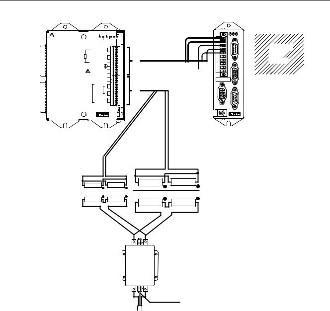
PL1100 EMC Installation Guidelines
These EMC installation recommendations are based on the expertise acquired during the development of compliant applications, which Parker believes are typical of the way, a PL1100 may be used. Provided you have no special installation requirements or untypical operating environment requirements, PL1100 power supplies will conform to current EMC
Directives.
If you are using the recommended transformers (TO255 & TO256) both primaries can be fed from a single EMC filter. Use a CORCOM 12FC10 or its equivalent. See Figure 3-5.
Mount the supply on a conductive panel to which the EMC filter and the drive(s) are also attached. If the panel has a paint finish, it will be necessary to remove the paint in certain areas to ensure the filter and supply, make a good large-area metal to metal contact with the panel.
Position the PL1100 as close as possible to the drives it is to supply (less than one metre).
Ideally, the EMC filter needs to be close to the transformers, which in turn, should be as close to the PL1100 as can be arranged. Assuming the use of an equipment cabinet, locate the EMC filter and transformers in the base of the cabinet and route AC supply cables up to the PL1100. Attempt to layout the wiring in a way that minimises cross coupling between filtered and non-filtered conductors. This means avoiding running wires from the output of a filter close to those connected to its input. Where you wish to minimise the cross coupling between wires avoid running them side-by-side one another, if they must cross, cross them at 90° to each other. Keep wiring supported and close to cabinet metalwork.
HV Transformer Specification (TO255)
Power rating |
1000VA |
|
|
Input voltage |
230V +15% -10% |
||
Output voltage |
2 |
X 50V |
RMS full load voltage |
Output current |
2 |
X 10A |
RMS |
Regulation |
3.5% |
|
|
Size |
162mm diameter, 70mm height |
||
Weight |
6.5Kg |
|
|
Mounting |
resin filled centre, drilled to accept an 8mm mounting screw. |
||
See note 1, over the page.
Suitable Transformer (TO256)
A +24V DC logic supply can use the TO256 120VA toroidal transformer, which has the following specification:
Power rating |
120VA |
|
Input voltage |
230V +15% -10% |
|
Output voltage |
2 |
X 18V RMS full load voltage |
Output current |
2 |
X 3.3A RMS |
Regulation |
5.5% |
|
Size |
93mm diameter, 46mm height |
|
Weight |
1.2Kg |
|
Mounting |
resin filled centre, drilled to accept an 8mm mounting screw. |
|
See note 1, over the page.
3. ELECTRICAL INSTALLATION 19
CAUTION
Risk of electric shock.
High voltage remains on terminals after power is removed.
Allow 5 minutes for capacitors to discharge.
PL1100
Power Supply
HV +24V
REGEN
X1
MOTOR HV OUT
MOTOR 0V.
EXT. BRAKING RES.
PE
+24V DC OUT
0V
20V AC IN
20V AC IN
LINK L3
FOR
55V SINGLE PHASE
AC IN L2 1/3 PH.
L1
X2
|
|
HV STFB |
|
|
X1 |
|
|
10 |
|
|
X3 |
|
|
CABINET |
|
|
BACK |
X1 |
|
PLANE |
|
|
X4 |
|
To star earth point |
1 |
|
|
|
|
|
X2 |
X2 |
|
X5 |
|
|
TO256 TO255
Transformers
Output |
(load) |
12FC10
Input |
(line) |
To star earth point on the metal
backplane
AC Mains input
Figure 3-5. Using a single EMC Filter for PL1100 Supplies
Note 1: A Neoprene insulating disc is included with the mounting kit to prevent the crushing of transformer windings. This disc provides a 5kV isolation barrier between the transformer and mounting panel.

20 VIX AE SERVO DRIVE USER GUIDE
SMB Motor Cables
The following motor power and feedback cables are available for ViX drives:
Power cable |
Feedback cable |
VIX-PWR-XXXX |
VIX-FDB-XXXX |
Table 3-3. Motor Power and Feedback Cables
Where XXXX is the length of the cable in cm, up to a maximum length of 20 metres in 2.5 metre increments. In the case of SMB motor cables the feedback cable can be used for resolver or encoder feedback.
BE & SM Motor Cables
When using BEor SM-Series motors choose the appropriate connector option to ensure the temperature sensor output is made available on the required connector:
• BE- |
nMSn |
•SMnGSn
Motor power cables are identified using the number 71-021125-XX, where XX is the length of the cable in feet, up to a maximum of 50ft (15.24m) in 5ft (1.524m) increments.
The form of feedback cable used with both the BEand SMrange will depend upon the type of feedback transducer:
• |
Resolver feedback |
71-021123-XX |
• |
Encoder feedback |
71-021124-XX |
Once again XX defines the length in ft.
Should you require a BE or SM servo motor with a mechanical brake, please contact
Parker. See the front of this user guide for contact details.
3. ELECTRICAL INSTALLATION 21
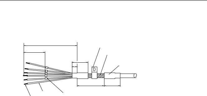
SMB Motor Connections at the Drive
Standard motor power cables are prepared for connection at the drive end as shown in Figure 3-6.
100 |
40 |
1 |
2 |
3 |
4 |
5 |
Stainless steel 'P' clip clamped firmly over folded back braiding (do not over-tighten)
|
Fold braiding back over the cable's outer |
|
insulation |
|
30 |
10 |
Heatshrink Sleeving |
|
Use relevant sleeving to suit cable diameter |
50 30
Green/yellow
Idents 1-5 (to UL94 C0)
Non-insulated boot-lace ferrules
All dimensions in millimetres
Figure 3-6. Motor Power Cable, Drive End Preparation
Note: The cable braiding is folded back over the outer insulation of the motor cable to give a larger diameter contact area and a mechanically strong fixing.
If you have a ready made ViX-PWR-XXXX cable, use the pre-fitted P-clip otherwise use one of the clips listed below:
Size |
Parker part number |
Comments |
9mm ID |
4216.101 |
- |
10.7mm ID |
4216.102 |
- |
12.3mm ID |
4216.103 |
Supplied with standard |
|
|
cables |
|
Table 3-4. P Clip sizes |
|
Three different size ‘P’ clips allow the use of a variety of motor power cables from different manufactures.
All motor connections must be made using a high quality braided-screen cable. Cables using a metallised plastic bandage for an earth screen are unsuitable and in fact provide very little screening. Care must be taken when terminating the cable screen, the screen itself is comparatively fragile; bending it round a tight radius can seriously affect the screening performance. The selected cable must have a temperature rating which is adequate for the expected operating temperature of the motor case.

22 VIX AE SERVO DRIVE USER GUIDE
SMB Motor Connections at the Motor
The motor power connections are made using a 6-way connector. Figure 3-7 shows the connector pin lettering and Table 3-5 gives the connectivity.
|
|
View looking |
1 |
5 |
into the cable |
|
|
socket |
|
6 |
|
2 |
|
4 |
3
Figure 3-7. Motor Power Connector Pin Identification
Drive end identity |
|
Motor connector |
Function |
X1 |
|
pin number |
|
4 black |
1 |
|
Phase U |
3 black |
2 |
|
Phase V |
2 black |
6 |
|
Phase W |
7 black (via fuse) |
4 |
|
Brake+ |
1 black |
5 |
|
Brake- |
5 green/yellow |
3 |
|
Gnd |
Table 3-5. Motor Power Cable Wiring
Motor feedback connections are made using a 17-way connector. Figure 3-8 shows the connector pin lettering and Table 3-6 gives the connectivity.
|
12 |
|
|
1 |
11 |
|
View looking |
|
|
10 |
into the cable |
2 |
|
socket |
|
|
|
||
13 |
|
|
16 |
|
|
|
|
3 |
|
|
9 |
|
|
|
|
14 |
|
|
15 |
|
|
|
|
4 |
|
8 |
|
|
|
|
|
5 |
7 |
|
|
|
6 |
|
|
|
17 |
|
|
Figure 3-8. Motor Feedback Connector Pin Identification
3. ELECTRICAL INSTALLATION 23
15-way D- |
Motor |
Resolver |
Encoder |
type pin |
feedback |
|
|
reference |
connector |
|
|
X2 |
pin |
|
|
1 |
15 |
Reserved |
Inc Enc Z+ |
2 |
16 |
Reserved |
Inc Enc Z- |
3 (twin) |
7 |
0V |
0V |
4 |
14 |
REFres+ |
Reserved |
5 (twin) |
8 |
+5V output |
+5V output |
6 |
7 |
0V |
0V |
6 |
13 |
Motor overtemp- |
Motor overtemp- |
7 |
1 |
SIN- |
Inc Enc A- |
8 |
2 |
SIN+ |
Inc Enc A+ |
9 |
4 |
Reserved |
Comm f-b A0 |
10 |
9 |
Motor overtemp+ |
Motor Overtemp+ |
11 |
12 |
COS- |
Inc Enc B- |
12 |
11 |
COS+ |
Inc Enc B+ |
13 |
5 |
Reserved |
Comm f-b A1 |
14 |
6 |
Reserved |
Comm f-b A2 |
15 |
17 |
REFres- |
Reserved |
*Note: two wires are used for the +5V supply (X2 pin 5) and two wires are used for 0V returns (X2 pin 3), two wires are also taken from X2 pin 6.
Table 3-6. Motor Feedback Cable Wiring
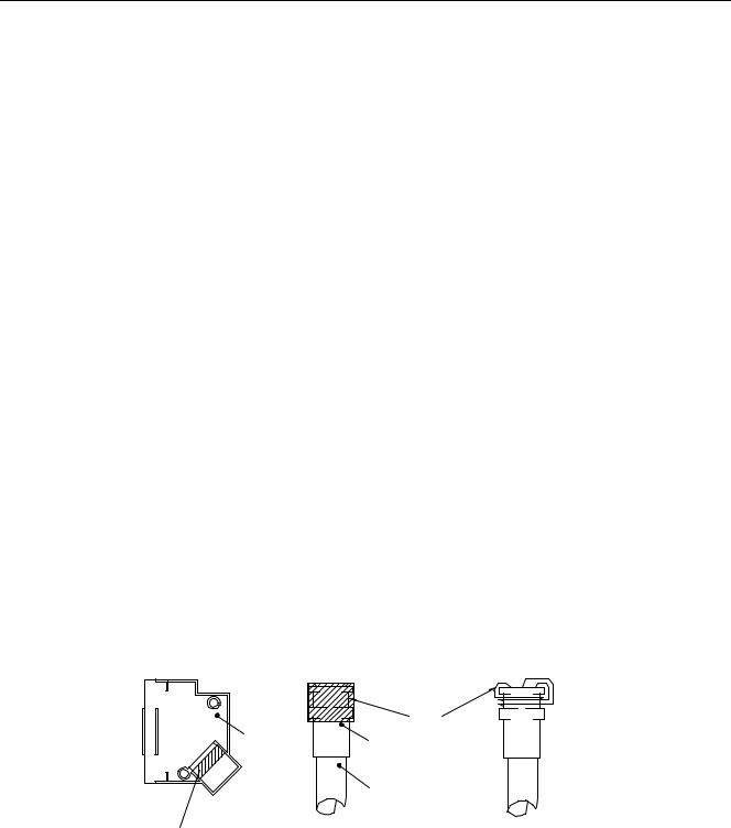
The 15-way D-type connector will require the feedback cable screen to be bonded to the metal connector shell, as shown in Figure 3-9.
RMI earth bonding required for both connectors
Example 1 |
Example 2 |
braid
cover
ferrule
cable
Earth bonding area |
Braid to be folded back over |
in cover |
complete cable ferrule to make |
|
a 360° connection. |
Braid to be made into 3 round forms and wrapped a round the recess of cable ferrule to make a 360° connection.
Figure 3-9. Screen Bonding Methods for D-type Connectors
A ferrite absorber, with a specification matching that of the Chomerics H8FE-1115-NC, is also required to be positioned on the feedback cable using heat shrink sleeving. The position of the absorber should be within 150mm of the feedback connector, as shown in Figure 3-10.
 Loading...