


 Loading...
COMPAX-M /-S (L)
C O M P A X U s e r G u i d e
C o m p a c t S e r v o C o n t r o l l e r
From software version V6.26 |
October 2001 |
|
E |
R T I F I |
E |
D |
|
|||
|
C |
|
|
|
|
|
|
|
|
DIN EN ISO 9001 |
|
||||||
W e a u t o m a t e m o t i o n |
Q |
|
|
|
|
|
|
M |
|
U |
|
|
|
|
|
E |
|
|
A |
L |
|
|
|
|
|
|
|
|
I |
|
T |
|
|||
|
|
|
S |
|
|
|||
|
|
|
|
|
T Y SY |
|
|
|
Reg. Nr. 36 38
Subject to technical modification.
Data correspond to the state of technical development at the time of printing.
Parker Hannifin GmbH |
Parker Hannifin plc |
||||||
EMD Hauser |
|
Electromechanical Division |
|||||
P. O. Box: 77607-1720 |
21 Balena Close |
||||||
Robert-Bosch-Str. 22 |
Poole, Dorset |
||||||
D-77656 Offenburg, Germany |
BH17 7DX UK |
||||||
Phone: |
+49 |
(0)781 509-0 |
Phone: |
+44 (0)1202 69 9000 |
|||
Fax: |
+49 |
(0)781 509-176 |
Fax: |
+44 (0)1202 69 5750 |
|||
http://www.parker-emd.com |
http://www.parker-emd.com |
||||||
|
11.10.01 11:01 |
192-040053 N2 |
|
|
|
|
|
|
|
|
|
|
|||
|
|
|
|
|
|||
|
|
|
|
|
|
|
|

Contents COMPAX-M / -S
1. Contents
1. |
Contents |
................................................................................................... |
2 |
|
|
|
|
||
2. |
Unit assignment: .................................................................................... |
7 |
||
|
|
|
||
3. |
Safety instructions................................................................................. |
8 |
||
|
3.1 |
General dangers ........................................................................................ |
8 |
|
|
3.2 |
Safe .............................................................................working practices |
8 |
|
|
3.3 |
Special .......................................................................safety instructions |
8 |
|
|
3.4 |
Conditions .............................................................................of warranty |
9 |
|
|
|
|||
4. COMPAX – CD........................................................................................... |
9 |
|||
|
|
|
||
5. |
Switch-on status................................................................................... |
10 |
||
|
5.1 |
Configuration when supplied................................................................. |
10 |
|
|
5.2 |
Commissioning ....................................................................................... |
10 |
|
|
5.3 |
Equipment ..........................................................................replacement |
12 |
|
|
|
|
||
6. |
Conditions for usage ........................................................................... |
13 |
||
|
|
|
||
7. |
Start-up manual .................................................................................... |
14 |
||
|
7.1 |
Overview: ................................................................................................. |
14 |
|
|
|
7.1.1 ....................................................................................... |
Components required |
14 |
|
|
7.1.2 ............................................................................Overview of unit technology |
15 |
|
|
7.2 |
COMPAX ........................................................................-M unit features |
17 |
|
|
|
7.2.1 ...............................................................Connector and terminal assignment |
17 |
|
|
|
7.2.2 ......................COMPAX-M system network, NMD10 / NMD20 mains module |
18 |
|
|
|
7.2.3 ............................................................... |
COMPAX - M dimensions/installation |
20 |
|
|
7.2.4 ................................................................ |
Connector assignment COMPAX - M |
21 |
|
7.3 |
Mains ................................................................module NMD10/NMD20 |
22 |
|
|
|
7.3.1 ................................................................................................... |
Overview NMD |
22 |
|
|
7.3.2 .................................................................................. |
Dimensions / installation |
22 |
|
|
7.3.3 ............................................................................. |
NMD connector assignment |
23 |
|
|
7.3.4 ..............................................................Technical data / power features NMD |
23 |
|
|
7.4 |
COMPAX ................................................................35XXS unit features |
26 |
|
|
|
7.4.1 .......................................Plug and connection assignment COMPAX 35XXM |
26 |
|
|
|
7.4.2 ...........................................Installation and dimensions of COMPAX 35XXM |
27 |
|
|
|
7.4.3 .................................................................................... |
Wiring COMPAX 35XXM |
28 |
2

7.4.4 COMPAX 35XXM connector assignment ........................................................ |
29 |
7.5 COMPAX 25XXS unit characteristics .................................................... |
30 |
|
7.5.1 COMPAX 25XXS connector and connection assignment.............................. |
30 |
|
7.5.2 COMPAX 25XXS-specific technical data......................................................... |
32 |
|
7.5.3 |
COMPAX 25XXS dimensions / installation ..................................................... |
33 |
7.5.4 |
Connector assignment COMPAX 25XXS ........................................................ |
34 |
7.6 COMPAX 45XXS/85XXS unit characteristics ........................................ |
35 |
|
7.6.1 Plug and connection assignment COMPAX 45XXS/85XXS ........................... |
35 |
|
7.6.2 COMPAX 45XXS/85XXS installation / dimensions ......................................... |
36 |
|
7.6.3 |
COMPAX 45XXS/85XXS-specific wiring .......................................................... |
37 |
7.6.4 |
COMPAX 45XXS/85XXS connector and pin assignment ............................... |
39 |
7.7 COMPAX 1000SL Unit characteristics................................................... |
40 |
|
7.7.1 Connector and terminal assignment for COMPAX 1000SL ........................... |
40 |
|
7.7.2 Connector assignment COMPAX 1000SL (overview) .................................... |
42 |
|
7.7.3 |
Mounting and dimensions COMPAX 1000SL ................................................. |
43 |
7.7.4 |
Safety chain / emergency stop functions ....................................................... |
44 |
7.8 |
Connections to the motor....................................................................... |
46 |
|
|
7.8.1 |
Resolver / SinCos.............................................................................................. |
46 |
|
7.8.2 |
Additional brake control................................................................................... |
51 |
7.9 |
Interfaces ................................................................................................. |
52 |
|
|
7.9.1 |
Digital inputs and outputs (excluding COMPAX 1000SL).............................. |
52 |
|
7.9.2 |
Digital inputs and outputs for COMPAX 1000SL............................................ |
53 |
|
7.9.3 |
Technical data / Connections of inputs and outputs..................................... |
54 |
|
7.9.4 |
Initiators and D/A monitor ................................................................................ |
55 |
|
7.9.5 |
Service D/A monitor / override......................................................................... |
56 |
|
7.9.6 |
Service D/A monitor.......................................................................................... |
56 |
|
7.9.7 |
D/A monitor option D1 ...................................................................................... |
58 |
|
7.9.8 |
RS232 interface ................................................................................................. |
59 |
|
7.9.9 |
Absolute value sensor (option A1) .................................................................. |
59 |
|
7.9.10 |
X13: Encoder interfaces, ... .............................................................................. 60 |
|
|
|
7.9.10.1 Encoder interfaces / analogue rpm specification for COMPAX............ |
60 |
|
|
7.9.10.2 Area of application of process interfaces ............................................. |
60 |
|
|
7.9.10.3 Encoder interfaces / Analogue rpm specification / Step direction |
|
|
|
input for COMPAX 1000SL .................................................................. |
61 |
|
7.9.11 |
HEDA interface (option A1/A4)......................................................................... |
63 |
|
7.9.12 |
Bus connection ................................................................................................. |
63 |
7.10 |
Technical data ......................................................................................... |
64 |
|
...........................................................................8. Operating Instructions |
67 |
||
8.1 |
Overview: ................................................................................................. |
67 |
|
|
8.1.1 Block structure of the basic unit (not applicable for COMPAX 1000SL)...... |
68 |
|
|
8.1.2 |
Password protection......................................................................................... |
70 |
8.2 |
Configuration........................................................................................... |
71 |
|
|
8.2.1 Front plate operation (not available with COMPAX 1000SL)......................... |
71 |
|
|
8.2.2 |
Configuration when supplied........................................................................... |
72 |
3

Contents |
|
COMPAX-M / -S |
||
|
8.2.3 |
Configuration process...................................................................................... |
72 |
|
|
8.2.4 |
Safety instructions for initial start-up ............................................................. |
73 |
|
|
8.2.5 |
Configurationparameters ................................................................................. |
74 |
|
|
8.2.6 |
Absolute value function with standard resolver ............................................ |
79 |
|
|
8.2.7 |
Machine zero mode........................................................................................... |
80 |
|
|
8.2.8 |
Limit switch operation ...................................................................................... |
89 |
|
8.3 |
Configuration via PC using "ServoManager" ....................................... |
91 |
||
|
8.3.1 |
Installing ServoManager................................................................................... |
91 |
|
|
8.3.2 |
Configuring COMPAX ....................................................................................... |
91 |
|
|
8.3.3 |
Individual configuration of synchronous motors........................................... |
91 |
|
8.4 |
Positioning and control functions ......................................................... |
95 |
||
|
8.4.1 |
Absolute positioning [POSA] ........................................................................... |
96 |
|
|
8.4.2 |
Relative positioning [POSR]............................................................................. |
96 |
|
|
8.4.3 |
Process velocity [SPEED] ................................................................................ |
97 |
|
|
8.4.4 |
Acceleration and braking time [ACCEL] ......................................................... |
97 |
|
|
8.4.5 |
Setting/resettingan output [OUTPUT] ............................................................. |
98 |
|
|
8.4.6 |
Setting multiple digital outputs [OUTPUT O12=1010]................................... |
98 |
|
|
8.4.7 |
Switch off drive unit. [OUTPUT O0] ................................................................. |
98 |
|
|
8.4.8 |
OUTPUT O0=... in program............................................................................... |
98 |
|
|
8.4.9 |
Password [GOTO] ............................................................................................. |
99 |
|
|
8.4.10 |
External velocity specification. [SPEED SYNC] ............................................. |
99 |
|
|
8.4.11 |
Mark-related positioning [POSR] ................................................................... |
100 |
|
|
8.4.12 |
Preparatory instructions................................................................................. |
101 |
|
|
8.4.13 |
Changes in speed within a positioning process [POSR SPEED] ............... |
101 |
|
|
8.4.14 |
Comparators during positioning [POSR OUTPUT] ...................................... |
103 |
|
|
8.4.15 |
Cam controller with compensation for switching delays ............................ |
104 |
|
|
8.4.16 |
Programmable waiting time [WAIT]............................................................... |
107 |
|
|
8.4.17 |
Program jump [GOTO].................................................................................... |
107 |
|
|
8.4.18 |
Sub-program jump [GOSUB].......................................................................... |
107 |
|
|
8.4.19 |
Instruction to end a sub-program. [RETURN] .............................................. |
107 |
|
|
8.4.20 |
END instruction [END] .................................................................................... |
107 |
|
|
8.4.21 |
Start a program loop [REPEAT] ..................................................................... |
108 |
|
|
8.4.22 |
Branching [IF I7=1].......................................................................................... |
108 |
|
|
8.4.23 |
Binary IF query of inputs [IF I12=101-1] ........................................................ |
108 |
|
|
8.4.24 |
Comparative operations ................................................................................. |
109 |
|
|
8.4.25 |
Specific processing of data record groups. WAIT START. ......................... |
109 |
|
|
8.4.26 |
Jump with data record selection [GOTO EXT] ............................................. |
109 |
|
|
8.4.27 |
Sub-program jump with data record selection [GOSUB EXT] ................... |
110 |
|
|
8.4.28 |
Error handling [IF ERROR GOSUB]............................................................... |
110 |
|
|
8.4.29 |
STOP / BREAK handling [IF STOP GOSUB xxx] .......................................... |
111 |
|
|
8.4.30 |
Arithmetic ........................................................................................................ |
113 |
|
|
|
8.4.30.1 |
Parameter assignments ..................................................................... |
113 |
|
|
8.4.30.2 |
Arithmetic and variables..................................................................... |
114 |
|
8.4.31 |
Position monitoring (P93=1, 2, 3) .................................................................. |
117 |
|
|
8.4.32 |
Idle display....................................................................................................... |
119 |
|
|
8.4.33 |
Speed monitoring in speed control mode (P93="4") ................................... |
120 |
|
|
8.4.34 |
PLC sequential step tracking ......................................................................... |
122 |
|
|
8.4.35 |
Engaging and disengaging the motor brake ................................................ |
123 |
|
|
8.4.36 |
Output of variable voltage .............................................................................. |
124 |
|
4

8.5 |
Optimization functions ......................................................................... |
125 |
|
|
8.5.1 |
Optimization parameters ................................................................................ |
127 |
|
8.5.2 |
Speed monitor ................................................................................................. |
132 |
|
8.5.3 |
Optimization display ....................................................................................... |
133 |
|
8.5.4 External position localization with position adjustment ............................. |
136 |
|
8.6 |
Interfaces ............................................................................................... |
|
138 |
|
8.6.1 Digital inputs and outputs .............................................................................. |
138 |
|
|
8.6.1.1 Digital inputs and outputs for COMPAX 1000SL................................ |
140 |
|
|
8.6.1.2 Free assignment of inputs and outputs .............................................. |
143 |
|
|
8.6.1.3 |
COMPAX virtual inputs ...................................................................... |
145 |
|
8.6.1.4 I/O assignment of variants ................................................................. |
147 |
|
|
8.6.1.5 |
Function of inputs............................................................................... |
148 |
|
8.6.1.6 Synchronous STOP using I13............................................................ |
151 |
|
|
8.6.1.7 |
Function of outputs ............................................................................ |
153 |
|
8.6.1.8 |
Diagrams:........................................................................................... |
154 |
|
8.6.2 PLC data interface (function not available with COMPAX 1000SL) ............ |
156 |
|
|
8.6.3 RS232 interface ............................................................................................... |
160 |
|
|
8.6.3.1 |
Interface description........................................................................... |
160 |
|
8.6.3.2 |
Interface functions.............................................................................. |
162 |
|
8.6.3.3 Read and write program sets and parameters................................... |
163 |
|
|
8.6.3.4 Binary data transfer using RS232 ...................................................... |
166 |
|
|
8.6.4 Process coupling using HEDA (Option A1 / A4)........................................... |
168 |
|
..................................................................9. Accessories and options |
173 |
||
9.1 |
System concept..................................................................................... |
173 |
|
9.2 |
Overview ................................................................................................ |
174 |
|
9.3 |
Motors .................................................................................................... |
176 |
|
9.4 |
HAUSER linear actuators ..................................................................... |
177 |
|
9.5 |
Data interfaces....................................................................................... |
178 |
|
|
9.5.1 |
RS232 ............................................................................................................... |
178 |
|
9.5.2 |
Bus systems .................................................................................................... |
178 |
|
|
9.5.2.1 Interbus-S / Option F2........................................................................ |
178 |
|
|
9.5.2.2 RS485 / Option F1/F5 ........................................................................ |
178 |
|
|
9.5.2.3 Profibus / option F3............................................................................ |
178 |
|
|
9.5.2.4 CAN - Bus / Option F4 ....................................................................... |
178 |
|
|
9.5.2.5 CANopen / Option F8......................................................................... |
178 |
|
|
9.5.2.6 CS31system bus / Option F7 ............................................................. |
178 |
9.6 |
Process interfaces ................................................................................ |
179 |
|
|
9.6.1 |
Encoder interface............................................................................................ |
179 |
|
9.6.2 Absolute value sensor (A1) ............................................................................ |
183 |
|
|
|
|
183 |
|
9.6.3 High resolution SinCos sensor system (S1/S2) ......................................... |
||
|
9.6.4 Option S3 for linear motors............................................................................ |
184 |
|
|
9.6.5 |
HEDA interface ................................................................................................ |
185 |
|
9.6.6 |
D/A monitor (D1) (option not available with COMPAX 1000SL) ................. |
185 |
9.6.7Analogue speed specification (E7) (option not available with COMPAX
1000SL) |
............................................................................................................ 186 |
9.7 Accessories ........................................................................................... |
187 |
5

|
Contents |
|
|
COMPAX-M / -S |
||
|
|
9.7.1 |
External control panel (not available for COMPAX 1000SL) |
....................... 187 |
|
|
|
|
9.7.2 |
Terminal module for COMPAX 1000SL (EAM) .............................................. |
188 |
|
|
|
|
9.7.3 |
EAM5/01: DC feed for COMPAX - M ................................................................. |
189 |
|
|
|
|
9.7.4 |
EMC measures ................................................................................................ |
191 |
|
|
|
|
|
9.7.4.1 |
Power filter ......................................................................................... |
191 |
|
|
|
|
9.7.4.2 |
Motor output throttle........................................................................... |
192 |
|
|
|
9.7.5 |
External ballast resistors ................................................................................ |
193 |
|
|
|
|
9.7.6 |
ServoManager ................................................................................................. |
200 |
|
|
|
|
9.7.7 |
Hand - held terminal .......................................................................................... |
200 |
|
|
9.8 |
Appendix: COMPAX components....................................................... |
206 |
|
|||
|
|
|
|
|
|
|
|
10.Appendix |
.............................................................................................. |
|
207 |
|
|
|
10.1 Status values of the standard unit (COMPAX XX00).......................... |
207 |
|
|||
|
10.2 Additional COMPAX measuring quantites.......................................... |
210 |
|
|||
10.3 |
COMPAX ..............................................................................parameter |
212 |
|
|||
|
|
10.3.1 ..................................................... |
VP parametercan be modified "On Line" |
212 |
|
|
|
|
10.3.2 ...................................................................... |
COMPAX standard parameters |
212 |
|
|
|
|
10.3.3 ..................................................... |
Monitoring and limitation characteristics |
222 |
|
|
|
10.4 Error handling and error messages .................................................... |
223 |
|
|||
|
|
|
|
|||
|
11.Application examples ........................................................................ |
226 |
|
|||
|
|
11.1.1 .......................................................................................................... |
Overview |
226 |
|
|
|
|
11.1.2 ....................................................................... |
External data record selection |
227 |
|
|
|
|
11.1.3 .......................................................................... |
Mark - referenced positioning |
229 |
|
|
|
|
11.1.4 .................................... |
Speed step profiling / comparator switching points |
231 |
|
|
|
|
11.1.5 ................................................................................................... |
SPEED SYNC |
233 |
|
|
|
|
11.1.6 ........................................................................................ |
Speed control mode |
234 |
|
|
|
|
11.1.7 .......................................................................................................... |
Fast start |
236 |
|
|
|
|
11.1.8 .................................................................. |
Implementing a torque controller |
237 |
|
|
|
|
|
|
|
|
|
|
12.Index ..................................................................................................... |
|
|
238 |
|
|
Data security
The parameter and program memory are created using ZP-RAM. This memory is unaffected by mains power failure.
This module has a guaranteed service life of 10 years (calculated from the first start-up).
ZP-RAM failure causes data loss; COMPAX contains wild data. If you encounter problems of this kind, contact HAUSER.
SinCos is a registered trademark of Firma Stegmann.
6
General dangers
2. Unit assignment:
Key to unit designation
HAUSER type plate
Notes for repeat customers regarding modified software versions:
This documentation applies to the following units:
!COMPAX 10XXSL
!COMPAX 25XXS
!COMPAX 45XXS
!COMPAX 85XXS
!COMPAX P1XXM
!COMPAX 02XXM
!COMPAX 05XXM
!COMPAX 15XXM
!COMPAX 35XXM
XX:Unit variants
e.g.: COMPAX 0260M:
COMPAX: name
02:performance class
60: |
Variant |
e.g. "00": |
Standard model |
|
|
"60": |
electronic transmission |
M: |
unit type |
"M": |
multi-axis model |
|
|
"S": |
single-axis unit |
|
|
... |
|
The type plate is located on the upper side of the unit and contains the following:
038106 0001 951-160101 Compax 0260M
E2
option name |
equipment |
|
name |
||
|
||
serial number |
part number |
Please check the software version of your unit.
Despite all efforts on our part, software modifications may change procedures as well as cause functional changes.
Please notify us immediately if you detect unexplainable problems when using a new software version.
7

Safety instructions |
COMPAX-M / -S |
3. Safety instructions
3.1General dangers
General dangers when safety instructions are not complied with
The unit described contains leading edge technology and is operationally reliable. However, hazards may occur if the unit is employed incorrectly or for improper use. Energized, moving or rotating parts can
!cause fatal injury to the user
!cause material damage
Proper use
This unit is designed for use in high voltage units (VDE0160). This unit automates motion processes. The ability to switch several units at once makes it possible to combine several motion processes. Reciprocal interlocks must be installed in such cases.
3.2Safe working practices
The unit must be operated by skilled staff only.
!When used in this manual, the term "trained staff" refers to people who,
•due to their training, experience and knowledge of current standards, guidelines, accident prevention regulations and operating conditions, have received authorization from the head of health and safety at the site to perform the necessary activities, while recognizing and avoiding any associated dangers (definition of personnel as per VDE105 or IEC364)
•are familiar with first aid and the on-site safety equipment,
•have read and observed the safety instructions
•have read and observed the User Guide (or the section which applies to the tasks to be executed).
This applies to all tasks relating to set-up, start-up, configuration, programming and modification of the operating conditions, operating modes and maintenance. Please note in particular the functions contained in the start-up manual relating to operational readiness and emergency stop.
The User Guide must be present at the unit at all times.
3.3Special safety instructions
!Check the arrangement of unit and documentation.
!Never disconnect the electrical connections when energized.
!Use safety equipment to ensure that moving or rotating parts cannot be touched.
!Ensure that the unit is in perfect working order before operation.
!Include the operational readiness and emergency stop functions of the unit (see start-up manual) in the safety and emergency stop functions of your machine.
!Only operate unit with the front cover attached.
!Ensure mains module has sufficient nominal and peak power ratings.
!Ensure that the unit arrangement enables the units with higher power ratings to be fitted more closely to the power unit than the units with lower ratings (COMPAX-M).
!Ensure that motors and linear drive units (if available) are sufficiently secured.
!Ensure that all energized connectors cannot be touched. The unit carries voltages ratings of up to 750V, which could fatally injure the operator.
!Please mind the limits of the mechanical equipment connected.
8

Conditions of warranty
3.4Conditions of warranty
!The unit must not be opened.
!Do not make any alterations to the unit, except for those described in the User Guide.
!Only activate inputs, outputs and interfaces as described in the User Guide.
!When installing units, ensure that the heat sinks receive sufficient ventilation.
!Secure units as per the assembly instructions contained in the start-up manual using the securing bores provided for this purpose. We cannot assume any responsibility for any other methods used for securing the units.
Note on option exchange
In order to check hardware and software compatibility, it is necessary for COMPAX options to be changed at the factory.
4. COMPAX – CD
On the accompanying CD, you will find all instructions for COMPAX and the operating software "ServoManager".
Once the CD is inserted in a Windows – computer, the HTML desktop (default.htm) is normally automatically started – if an Internet browser is present. If you do not have an Internet browser on your computer, please install a version: the software is usually available to download free of charge.
If the desktop does not start automatically, please execute the file "default.htm" (e.g. by double clicking on the file or via "Start":"Run"). The "default.htm" file is located directly on the CD (not in the sub-directory).
Use Language selection (top right in window) to select the language required.
Follow the CD instructions shown on the window in the center of the screen.
Use the list on the left-hand side to select the required instructions or software.
9
Switch-on status |
COMPAX-M / -S |
5. Switch-on status
5.1Configuration when supplied
When supplied, COMPAX is not configured. Parameter P149 is set to "0": P149="0": COMPAX is not configured and switches to OFF mode when switched
on (24V DC and operating voltage) (motor switched off). In addition to this, when switched on, all parameters (apart from bus settings P194, P195, P196 and P250) are set to their default values.
P149="1": COMPAX is configured and once switched on (24V DC and operating voltage) tries to engage the motor.
5.2Commissioning
Meaning of LEDs on the front panel
COMPAX-M / -S
LED |
Color |
Meaning, when switched on |
Ready |
green |
24V DC present and initialization complete |
Error |
red |
COMPAX - Error (E1...E56) present or COMPAX is |
|
|
initialized. |
Mains module
LED |
LED |
Possible errors |
red |
green |
|
Error |
Ready |
|
off |
on |
no errors |
on |
off |
Heat sink temperature too high or |
|
|
error in logic voltage (24V DC too low or unit is defective) |
|
|
Emergency stop is activated and ready contact is |
|
|
released. |
on |
on |
Ballast switching unit overload or |
|
|
undervoltage (<100V DC or <80V AC). |
COMPAX 1000SL
Status |
Red LED (H2) |
Green LED (H1) |
24V not available |
off |
off |
24V are switched on, boot up |
on |
off |
Unit OFF |
off |
blinking |
Unit error; drive switched off |
on |
blinking |
Unit error; drive powered |
on |
on |
Unit RUNNING |
off |
on |
Caution!
If there is no control voltage, no displays will appear to indicate that operating voltage is present.
Note: With Error E40, external enabling is missing with COMPAX 45XXS, COMPAX 85XXS and COMPAX 1000SL (Hardware input).
10
Commissioning
After 24V DC of control voltage is switched on, COMPAX has two statuses available once the initialization phase has been completed:
1.COMPAX is OFF
COMPAX is not configured (P149="0") or with COMPAX XX70:
I12="0" (final stage blocked).
Now configure COMPAX (e.g. using the ServoManager / ParameterEditor). Set P149="1"
Configuration is accepted with VC and VP of COMPAX.
2.COMPAX displays error E57
COMPAX is configured (P149="1"). However, operating voltage is not present. Check COMPAX configuration* .
Alterations are accepted with VC and VP of COMPAX.
*) Configuring
a)Using ServoManager:
P149="1", VP and VC are transferred when being downloaded to COMPAX from the ServoManager.
b)Using hand-held terminal:
P149="1", VP and VC are generated by the hand-held terminal.
c)Without an auxiliary device, e.g. a terminal:
P149="1", VP and VC must be transmitted after COMPAX configuration.
Switch on operating voltage
With E57: acknowledge error by pressing Enter. When OFF: command: "OUTPUT O0=0" or
switch 24V DC on / off
Motor is powered; COMPAX display shows "RUN". Flow chart:
initializing stage
COMPAX configured |
COMPAX not configured |
||
(P149="1") |
|
(P149="0") |
|
|
|
OFF in |
|
|
|
Display |
|
|
|
|
|
|
|
|
|
|
|
execute |
|
|
|
configuration |
|
|
|
|
|
|
|
|
|
|
|
P149="1", |
|
|
|
VC, VP |
|
connect DC bus voltage
24V DC |
OUTPUT |
ON / OFF |
O0="0" |
RUN motor enabled
11

Switch-on status |
COMPAX-M / -S |
5.3Equipment replacement
Previous software ≥ V2.0
!Procedure for copying the complete COMPAX setting onto a new unit
!Start ServoManager.
!Connect old COMPAX via RS232.
!Use menu "Insert: Axis: From controller" to set up an axis which contains all COMPAX settings (all parameters: including system parameters, data records and (with COMPAX XX70) existing curves).
!Connect new COMPAX.
!Use menu "Online: Download" to transfer data (without system parameters1) into the new COMPAX.
Transferring system parameters
!Call up ParameterEditor (Menu: PC Tools: ParameterEditor)
!Use menu "Online: Copy" menu to transfer all parameters (including system parameters) to COMPAX.
Previous software ≤ V2.0
Procedure for copying the complete COMPAX setting onto a new unit
!Start ServoManager.
!Connect old COMPAX via RS232.
!Use menu "Insert: Axis: New" to set up a new axis.
!Use menu "Online: Upload" to load all COMPAX settings (all parameters: including system parameters, data records, and (in COMPAX XX70) existing curves) into the new axis.
!Connect new COMPAX.
!Use menu "Online: Download" to transfer data (without system parameters) into the new COMPAX.
Transferring system parameters
!Call up ParameterEditor (Menu: PC Tools: ParameterEditor)
!Use menu "Online: Copy" menu to transfer all parameters (including system parameters) to COMPAX.
1System parameters are internal parameters; you will only obtain an identical COMPAX – setting if these are also transferred.
12
Equipment replacement
6.Conditions for usage
-for CE-compliant operation in industrial and
business sectors -
Power filter:
Motor and resolver cable:
Motors:
Control:
Earthing:
Cable laying:
Accessories
Warning:
The EU guidelines on electromagnetic compatibility 89/336/EEC and electrical means of production for use within particular voltage limits 73/23/EEC are satisfied, if the following peripheral conditions are complied with.
Only operate the units in the condition in which they are supplied, i.e. with all housing plates and the front cover.
COMPAX P1XXM, COMPAX 02XXM, COMPAX 05XXM and COMPAX 15XXM may only be operated with HAUSER mains modules (NMD10 or NMD20) or on COMPAX 35XXM.
A power filter is required in the power line. The filtering can be executed once for the entire system or as separate process for each unit.
The following power filters are required for standalone operation:
NMD10 / COMPAX 45XXS / COMPAX 85XXS: |
Order No.: NFI01/02 |
NMD20: |
Order No.: NFI01/03 |
COMPAX 35XXM: |
Order No.: NFI01/04 or /05 |
COMPAX 25XXS: |
Order No.: NFI01/01 or /06 |
COMPAX 10XXSL: |
Order No.: NFI01/01 or /02 |
Length of connection: connection between power filter and unit: unscreened: < 0.5m screened: < 5m
Only operate the unit with a HAUSER motor and resolver cable (with connectors containing special surface screening).
In such cases, the following cable lengths are permitted.
Motor cable |
< 100m |
(the cable must not be rolled up) |
|
For motor lines of >20m, a motor output throttle must be used |
|
|
Up to 16A nominal motor current: Type: MDR01/01 16A / 2mH. |
|
|
Between 16A and 30A: Type: MDR01/02 30A / 1.1mH. |
|
|
Over 30A nominal motor current: Type: MDR01/03 >30A / |
|
|
0.64mH. |
|
Resolver cable |
< 100m |
|
Operation with HAUSER motors.
Only operate with calibrated controller (avoid feedback oscillation).
!The filter housing, the mains module and the COMPAX must be surface connected with good metal conductivity and low inductivity to the cabinet ground.
!Never secure the filter housing or the unit to coated surfaces.
!Ensure that you have largest spacing possible between the signal and load lines.
!Signal lines must never pass sources of strong interference (motors, transformers, relays,...).
!Only use accessories recommended by HAUSER (absolute value sensor, encoder,...).
Provide large surface contact areas down both sides of all cable screening.
This is a product of the restricted sales class as per IEC 61800-3. In a domestic environment, this product may cause high frequency disturbances, in which case the user can be requested to implement suitable measures.
13

Start-up manual |
COMPAX-M / -S |
7. Start-up manual
C o m p a c t S e r v o C o n t r o l l e r
7.1 Overview:
7.1.1 Components required
In addition to a COMPAX, you will require the following components for a COMPAX application:
! a motor with or without a transmission. ! mains supply.
! emergency stop circuit.
! various cables for connecting components. !motor cable and resolver cable.
!supply line for voltage supply.
!supply line for 24V DC control voltage.
! hand-held terminal or PC (with RS232 cable) containing the ServoManager program for configuring COMPAX.
14
Overview:
Overview of unit technology
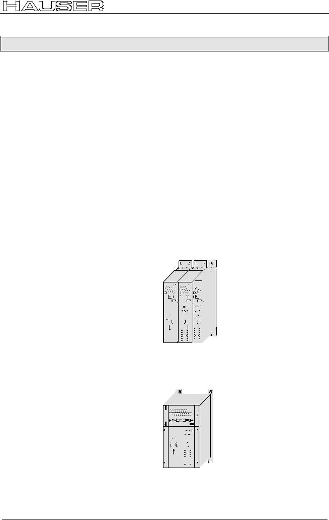
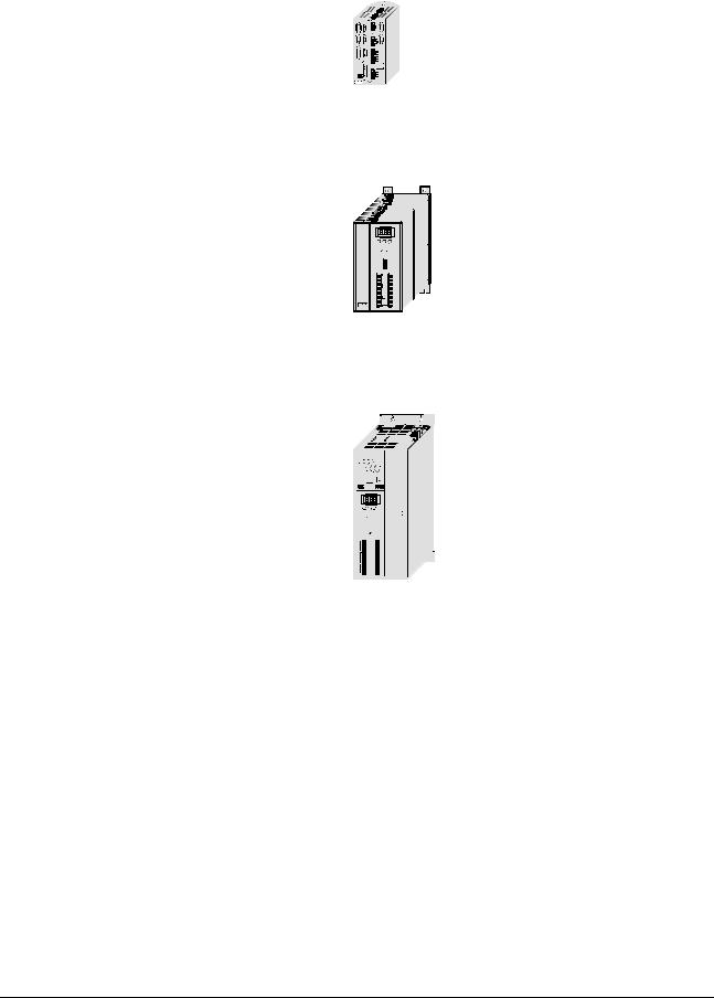
7.1.2 Overview of unit technology
COMPAX-M and COMPAX-S
!work with the same firmware, yet have differences with regard to
!housing and assembly technology and
!power areas.
The following table shows the main features of the range of available units
Common function characteristics:
COMPAX P1XXM COMPAX 02XXM COMPAX 05XXM COMPAX 15XXM
Interfaces: 16 (8 with COMPAX 1000SL) digital inputs/outputs, RS232; machine zero, limit switch, override input
Fieldbus options: RS485, Interbus-S, Profibus, CS31, CAN – Bus, CANopen, HEDA (synchronous serial realtime interfaces)
Other options (excluding COMPAX 1000SL): absolute encoder sensor; encoder input; encoder simulation; D/A monitor
Supply via central mains module: NMD10 / NMD20: Up to max. 3*500V AC
Dimensions (DxHxW): |
COMPAX P1XXM: |
|
340*400*60 [mm] |
Design: |
|
COMPAX-M with NMD |
|
mains module |
Power Supply COMPAX-M COMPAX-M |
Installation: in series |
|
COMPAX-M: 340*400*85 [mm]
Power: COMPAX ...
P1XXM: 3.8 kVA 02XXM: 4.5 kVA 05XXM: 8.0 kVA 15XXM: 17 kVA
COMPAX 35XXM |
Supply Up to max. 3 * 500V AC (integrated power unit) |
|
|
Dimensions (DxHxW): |
40 * 400 * 220 [mm] |
|
Design: |
Power |
|
|
35.0 kVA |
COMPAX-M |
Automation |
15
Unit |
hardware |
|
|
Connector |
assignment / cable |
Technical data |
|
|
|
Configuration |
|
|
|
Positioning and |
control functions |
|
|
Optimization |
functions |
|
|
Interfaces |
|
|
|
Accessories / |
options |
|
|
Status |
|
|
|
Parameter |
|
|
|
Error list |
|
|
|
Start-up manual |
COMPAX-M / -S |
COMPAX 1000SL
COMPAX 25XXS
COMPAX 45XXS COMPAX 85XXS
Supply Up to max. 1*250V AC (integrated power unit)
Dimensions (DxHxW): |
146*180*85 [mm] |
Design: |
Power |
|
1 kVA |
|
COMPAX - SL |
Supply Up to max. 1 (3)*250V AC (integrated power unit)
Dimensions (DxHxW): |
220*240*130 [mm] |
Design: |
Power |
|
2.5 kVA |
|
S-COMPAX |
Supply Up to max. 3*500V AC (integrated power unit)
Dimensions (DxHxW): |
275*350*125 [mm] |
Design: |
Power |
|
4.5 kVA |
COMPAX-S |
8.6 kVA |
|
16
COMPAX-M unit features
Connector and terminal assignment
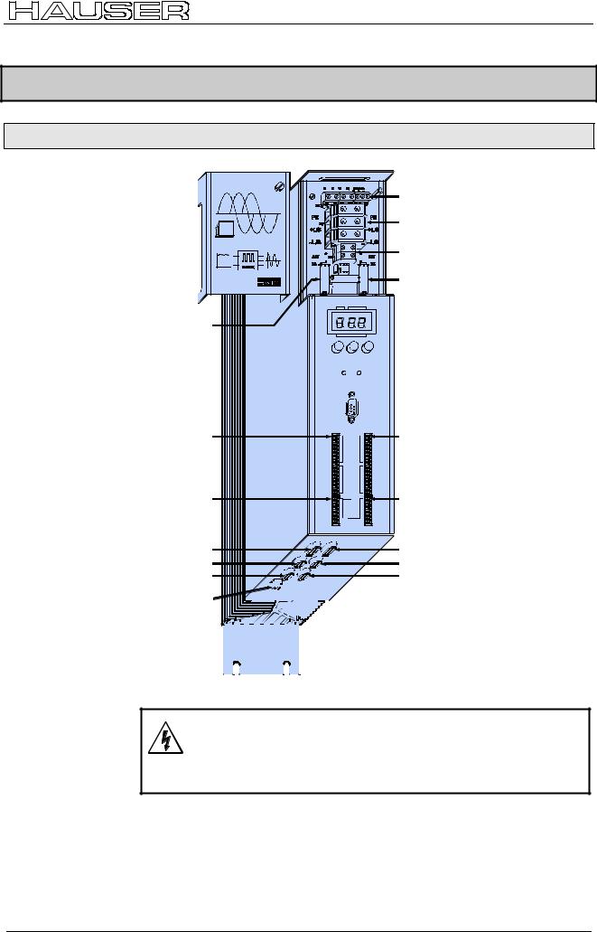
7.2COMPAX-M unit features
7.2.1 Connector and terminal assignment
COMPAX-M |
|
X1 |
motor |
X2 |
intermediate loop |
|
power connections |
X3 |
24V control voltage |
|
|
|
|
|
|
|
|
|
|
|
|
|
|
|
X4 |
controland status |
|
|
|
|
|
|
|
|
|
|
|
|
|
|
|
||
|
|
|
|
|
|
|
|
|
|
|
|
|
|
|
||
|
|
|
|
|
|
|
|
|
|
|
|
|
|
|
|
signals / bus signals |
|
|
|
|
|
|
|
|
|
|
|
|
|
|
|
|
|
|
|
|
|
|
|
S ta tu s N u m b e r |
or short circuit plug |
|||||||||
X5 controland |
|
|
|
|
|
|
|
|
|
|
|
statussignal |
|
|
|
|
|
bus-signals |
|
|
|
|
|
|
|
Value |
|||
input |
|
|
|
||
- |
+ |
E n te r |
|||
|
|
|
R eady |
E rro r |
|
|
|
|
X6 |
|
|


 X6 RS232
R S 2 3 2
X8 |
Input |
X8 |
X10 |
Input / Output |
/ Output |
|
X10 |
||
|
In p u t |
|
||
|
|
|
|
|
O u tp u t |
X9 |
Test |
Test |
X11 |
Control |
C o n tro l |
|
|
|
|
|
|
|
|
|
|
|
|
|
|
|
|
|
|
|
|
|
|
|
|
|
|
|
|
|
|
X9 |
X11 |
|
|
X12 |
resolver |
|
|
|
|
|
|
X13 |
Encoder |
||||||||||||||||||||||||
|
|
|
|
|
|
||||||||||||||||||||||||||||
|
|
|
|
|
|
|
|||||||||||||||||||||||||||
X14 HEDA |
|
|
|
|
|
|
|
|
X15 |
HEDA |
|||||||||||||||||||||||
|
|
|
|
|
|
|
|
|
|
||||||||||||||||||||||||
X16 |
absolute |
|
|
|
|
|
|
|
|
|
|
|
|
|
|
X17 |
initiators |
||||||||||||||||
|
|
|
|
|
|
|
|
|
|
|
|
|
|
||||||||||||||||||||
|
encoder |
|
|
|
|
|
|
|
|
|
|
|
|
|
|
|
|
|
|
|
|
||||||||||||
|
|
|
|
|
|
|
|
|
|
|
|
|
|
|
|
|
|
|
|
|
|||||||||||||
|
|
|
|
|
|
|
|
|
|
|
|
|
|
|
|
|
|
|
|
|
|||||||||||||
|
X18 fan |
|
|
|
|
|
|
|
|
|
|
|
|
|
|
|
|
|
|
|
|
|
|
|
|
|
|
||||||
|
|
|
|
|
|
|
|
|
|
|
|
|
|
|
|
|
|
|
|
|
|
|
|
||||||||||
|
|
|
|
|
|
|
|
|
|
|
|
|
|
|
|
|
|
|
|
|
|
|
|
|
|
|
|
|
|
|
|
|
|
|
|
|
|
|
|
|
|
|
|
|
|
|
|
|
|
|
|
|
|
|
|
|
|
|
|
|
|
|
|
|
|
|
|
|
|
|
|
|
|
|
|
|
|
|
|
|
|
|
|
|
|
|
|
|
|
|
|
|
|
|
|
|
|
|
|
|
|
Before wiring up, always de-energize the unit.
Even once the mains supply has been switched off, dangerous levels of voltage can remain in the system for up to 5 min.
Meaning of LEDs on |
LED |
Color |
Meaning, when switched on |
|
front plate |
|
|
|
|
Ready |
green |
24V DC present and initialization complete |
||
|
||||
|
Error |
red |
COMPAX - fault (I1...E56) present. |
17
Unit |
hardware |
|
|
Connector |
assignment / cable |
Technical data |
|
|
|
Configuration |
|
|
|
Positioning and |
control functions |
|
|
Optimization |
functions |
|
|
Interfaces |
|
|
|
Accessories / |
options |
|
|
Status |
|
|
|
Parameter |
|
|
|
Error list |
|
|
|
Start-up manual |
COMPAX-M / -S |
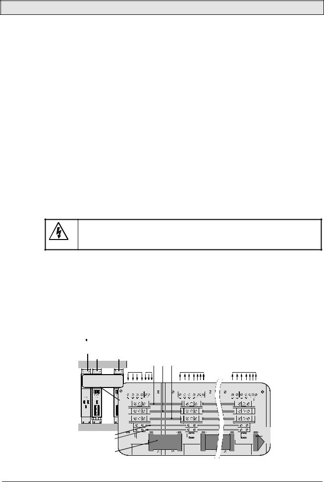
7.2.2 COMPAX-M system network, NMD10 / NMD20 mains module
Short circuit connectors
A COMPAX-M drive system consists of one mains module and one or more drive controllers. The units are coupled with one another with flatband cables (see below). These are arranged behind the front plate cover of the power unit and the drive controller.
The power unit converts mains power (up to 3 * 500V AC) into DC current for the intermediate circuit.
The two connectors for connection to the bus systems are located on the front plate of the power unit. The connection assignment complies with the specifications for 2-cable remote bus.
The 24V DC control voltage required by the system network is supplied from the power unit.
A connector terminal on the front of the power unit is used for connecting the control and status signals (EMERGENCY STOP, readiness) which you can incorporate in the control of the entire system.
These signals and the bus lines are connected internally via a preformed doublesided flatband cable. These cables are included with the drive controller. The connectors which receive these connection cables are housed under the front plate cover of the mains module and the drive controller.
Attach a short circuit connector to the outgoing connector on the drive controller that is furthest away from the mains module. The short circuit connector (order No. 102-908000) is included with the mains module.
Installation arrangement
Before wiring up, always de-energize the unit.
Even once the mains supply has been switched off, dangerous levels of voltage can remain in the system for up to 5 min.
Wiring up the system network
The wires required for creating the system network are included in the delivery. Open the front cover (upper section of front side) by loosening the top right knurled screw and wire up the following:
!24V DC voltage supply.
!PE and DC current.
!Emergency stop, ready and bus signals with a terminating connector on the last unit.
From the mains module to the individual COMPAX-M.
 When delivered, the terminating connector is located on the mains module.
power supply module COMPAX-M COMPAX-M
cable conduit |
|
|
PE |
LS+ LS- |
|
|
|
|
|
|
main |
24V |
|
motor |
|
|
motor |
|
|
L1 L2L3 PE 24V |
U |
V W PE brake |
U |
V W PE brake |
||
... |
|
|
+ - |
|
PE + - |
|
|
PE + - |
PEX1 |
|
|
X1 |
|
X1 |
|
|
|
|
X2 |
|
X2 |
|
X2 |
|
|
|
|
+LS |
|
|
|
|
|
|
|
|
-LS |
|
|
|
|
|
|
|
|
|
+ |
|
|
|
|
|
|
voltage supply { |
24V |
- X3 |
|
X3 |
X3 |
last device |
||
|
|
|
|
|
|
|
equiped |
|
|
|
|
|
|
|
|
with |
|
24V |
|
|
|
|
|
|
|
terminal |
emergency stop, |
|
|
|
|
|
|
|
plug |
|
|
|
|
|
|
|
|
|
stand by and bus |
|
|
X4 |
X5 |
X4 |
X5 |
|
X4 |
signals |
|
|
|
|
|
|
|
|
18

COMPAX-M unit features
Wiring up the motor
COMPAX-M system network, NMD10 / NMD20 mains module
Unit side |
|
|
|
|
|
|
|
|
|
|
U |
V W PE |
brake |
||||
cable conduit |
|
|
|
|
|
PE |
+ |
- |
|
|
black 1 |
black 2 |
black 3 |
green/ yellow |
free |
black 4 |
black 5 |
CO M PA X- M |
CO M PA X- M |
|
|
|
|
|
|
|
|
|
1 |
2 |
|
3 |
|
4 |
5 |
|
|
X1 |
|
|
|
|
|
|
|
|
L1 L2L3 PE 24V |
|
|
U V W PE brake |
|||
|
|
+ - |
|
|
|
PE+ - |
|
|
|
X1 |
|
|
X1 |
|
|
|
|
|
PE |
|
|
|
|
|
|
|
|
X2 |
|
X2 |
|
|
|
||
|
+LS |
|
|
|
|
|
|
|
|
-LS |
|
|
|
|
|
|
|
|
24V |
+X3 |
|
|
X3 |
|
|
|
|
|
- |
|
|
|
|
|
|
X4 |
X5 |
X4 |
Screened |
Note the screened connection of the motor cable on the |
|
|
|
|
|
|
||
connection |
upper unit side. |
|
|
|
Clamp the motor cable with the open place of the screen braid under the ground terminal (see figure on the right).
Only wire up brake in motors which have a holding brake! If not, do not wire.
Wiring up mains |
The mains supply and the control voltage supply are provided by the mains |
|
power / control |
module. |
|
voltage |
Power supply: |
Control voltage |
|
||
|
! 3*80V AC – max. 3*500V AC; 45 - 65Hz |
! 24V DC ± 10% |
|
! Fuse protection: |
Ripple <1VSS |
|
NMD10: 16A (K circuit breaker in 20A) |
Fuse protection: max. 16A |
|
NMD20: 35A |
|
|
K circuit breaker or similar Neozed |
|
|
fusible cut-out. |
|
|
cable conduit |
L1 L2 L3 PE |
24V |
||||
|
|
|
|
|
|
+ |
- |
HAUSER |
HAUSER |
COMPAX-M |
1 |
2 |
3 |
4 |
5 |
|
COMPAX-M |
||||||
|
|
|
X1 |
|
|
|
|
POWER SUPPLY |
CO MPAX -M |
|
|
|
|
|
|
|
|
|
L1 L2L3 PE 24V |
|
U V W PE brake |
||
|
|
|
|
+ - |
|
|
PE + - |
|
|
|
X1 |
|
|
X1 |
|
|
|
|
PE |
|
|
|
|
|
|
|
X2 |
|
|
X2 |
|
|
|
+LS |
|
|
|
|
|
-LS
|
+ |
|
24V |
- X3 |
X3 |
power supply module
X4 
 X5 X4
X5 X4
19
Unit |
hardware |
|
|
Connector |
assignment / cable |
Technical data |
|
|
|
Configuration |
|
|
|
Positioning and |
control functions |
|
|
Optimization |
functions |
|
|
Interfaces |
|
|
|
Accessories / |
options |
|
|
Status |
|
|
|
Parameter |
|
|
|
Error list |
|
|
|
Start-up manual |
COMPAX-M / -S |
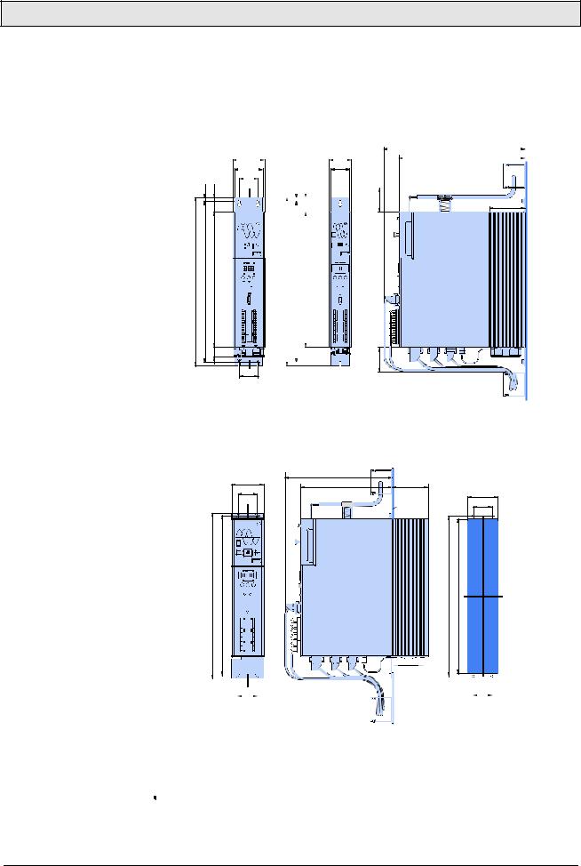
7.2.3 COMPAX-M dimensions/installation
The specific design of the COMPAX-M controller allows for wall installation (distance: 61mm in COMPAX P1XXM and 86mm in larger units) in two different ways.
Direct |
Direct wall installation and dimensions of COMPAX-M and the mains |
|||||||||||||
wall installation: |
modules. |
02XXM, 05XXM, |
|
P1XXM |
|
|
||||||||
|
|
|
|
|
||||||||||
|
|
15XXM, NMD10 |
|
|
|
|
|
|
||||||
|
|
|
|
& NMD20 |
|
|
|
|
390 |
|
||||
|
|
|
85 |
|
|
|
|
60 |
|
|
340 |
|
||
|
|
|
|
|
|
|
|
|||||||
|
|
|
75 |
|
|
|
|
49 |
|
|
|
|
||
|
|
50 |
|
|
|
|
|
|
|
|
|
|||
|
10 |
40 |
|
|
|
|
|
|
10 |
40 |
|
|
|
|
|
|
|
|
|
|
|
|
|
|
|
||||
65 |
96 |
|
COMPAX-M |
COMPAX-M |
||||||||||
|
|
|
|
|
|
|
|
|
|
|
|
|
|
|
|
|
|
|
|
|
|
|
|
|
|
|
|
|
|
|
|
|
|
|
|
|
|
|
|
|
|
|
|
|
|
|
|
|
|
|
|
|
|
|
|
|
|
|
|
|
|
|
|
|
|
|
|
|
|
|
|
|
|
|
|
|
|
|
|
|
|
|
|
|
|
|
|
|
|
|
|
|
|
|
|
|
|
|
|
|
|
|
|
|
|
|
|
450 |
430 |
364 |
450 |
430 |
364 |
|
|
31 |
|
|
65 |
|
|
|
|
|
|
|
|
|
50 |
|
|
Attach with four 6-mm |
Attach with two 6-mm |
hex-socket-head-screws |
hex-socket-head-screws |
The controllers are attached to the mounting plate with the back of the heat sink.
Indirect |
Indirect wall installation of COMPAX 02XXM, COMPAX 05XXM and COMPAX |
wall installation: |
15XXM and the mains modules NMD10 and NMD20. |
85 |
294 |
|
|
244 |
96 |
|
|
50 |
|
||
|
|
82 |
|
|
|
mounting |
|
|
|
50 |
|
|
|
plate |
|
COMPAX-M |
|
|
|
441,5 |
424 |
424 |
408 |
|
|
|
|
|
|
|
|
|
|
|
|
|
|
|
|
|
|
|
|
|
|
|
|
|
|
|
|
|
|
|
|
|
|
|
|
|
|
|
|
|
|
|
|
|
|
|
|
|
|
|
|
|
|
|
|
|
|
|
|
|
|
|
|
|
|
|
|
|
|
|
|
|
|
|
|
|
|
|
|
|
|
|
|
|
|
|
|
|
|
|
|
|
|
|
|
|
|
|
|
|
|
|
|
|
|
|
|
|
|
|
|
|
|
|
|
|
|
|
|
|
|
|
|
|
|
|
|
|
|
|
|
|
|
|
|
|
|
|
|
|
|
|
|
|
|
|
|
|
|
|
|
|
|
|
|
|
|
|
|
|
|
|
|
|
|
|
|
|
|
|
|
|
|
|
|
|
|
|
|
|
|
|
|
|
|
|
|
|
|
|
|
|
|
|
|
|
|
|
|
|
|
|
|
|
|
|
|
|
|
|
|
|
|
|
|
|
|
|
|
|
|
|
|
|
|
|
|
|
|
|
|
|
|
|
|
|
|
|
|
|
|
50 |
|
|
|
|
|
|
|
|
|
|
|
|
|
|
|
|
|
|
|
|
50 |
||||||
mounting  plate
plate
The heat sink is pushed back through a hole in the panel (on right of diagram). A separate heat chamber is created between the installation plate and the rear wall of the control cabinet. The angles required under designation MTS2 must be complied with.
 Indirect wall installation is not possible with COMPAX P1XXM.
Fan configuration |
Units with fan: |
COMPAX P1XXM, COMPAX 05XXM, COMPAX 15XXM |
|
Units without fan: |
COMPAX 02XXM, NMD10, NMD20 |
20
COMPAX-M unit features
Connector assignment COMPAX-M
7.2.4 Connector assignment COMPAX-M
*can be parameterized
|
|
|
|
|
|
|
|
|
|
|
|
|
|
|
|
|
|
|
|
|
|
|
|
|
|
|
|
|
|
|
|
|
|
|
|
|
|
|
|
|
|
|
|
|
|
|
|
|
|
|
|
|
|
|
|
|
|
|
|
|
|
|
|
|
|
|
|
|
|
|
|
|
|
|
|
|
|
|
|
|
|
|
|
|
|
|
|
|
|
|
|
|
|
|
|
|
|
|
|
|
|
|
|
|
|
|
|
|
|
|
X1: |
|
|
|
|
|
|
X2: |
|
|
|||||||||||||||||||
|
|
|
|
|
|
motor |
|
|
|
|
|
|
power inter- |
|
|
|||||||||||||||||||
|
|
|
|
|
|
brake |
|
|
|
|
|
|
mediate loop |
|
|
|||||||||||||||||||
X8: input / output I1...I8 O1...O8
X10: input / output I9...I16 O9...O16
X9
X12: resolver / SinCos
housing |
+8V |
NC |
REF- |
SIN- |
NC |
GND |
ST+ |
+5 V |
TEMP |
COS- |
COS+ |
SIN+ |
REF+ |
ST- |
|||||||||||||||
|
|
|
|
|
|
|
|
|
|
|
|
|
|
|
|
|
X12/10 |
|
X12/11 |
|
X12/12 |
|
X12/13 |
|
X12/14 |
|
X12/15 |
|
|
X12/1 |
|
X12/2 |
|
X12/3 |
|
X12/4 |
|
X12/5 |
|
X12/6 |
|
X12/7 |
|
X12/8 |
|
X12/9 |
|
|
|
|
|
|
|
||||||
|
|
|
|
|
|
|
|
|
|
|
|
|
|
|
|
|
|
|
|
|
|
|
|
|
|
|
|
|
|
|
|
|
|
|
|
|
|
|
|
|
|
|
|
|
|
|
|
|
|
|
|
|
|
|
|
|
|
|
|
|
|
|
|
|
|
|
|
|
|
|
|
|
|
|
|
|
|
|
|
|
|
|
|
|
|
|
|
|
|
|
|
|
|
|
|
|
|
|
|
|
|
|
|
|
|
|
|
|
|
|
|
|
|
|
|
|
|
|
|
|
|
|
|
|
|
|
|
|
|
|
|
|
|
|
|
|
|
|
|
|
|
|
|
|
|
|
|
|
|
|
|
|
|
|
|
|
|
|
|
|
|
|
|
|
|
|
|
|
|
|
|
|
|
|
|
|
|
|
|
|
|
|
|
|
|
|
|
|
|
|
|
|
X3: |
|
|
|
|
|
|
|
|
|
|
|
|
|
|
|
|
X6: |
|
|
|
|
|
|
|
|
|
|
|
|
|
|
|
|
|
|
|
|
|
|
|
|
|
||||||||||
|
control |
|
|
|
|
|
|
|
|
|
|
|
RS232 |
|
|
|
|
|
|
|
|
|
|
|
|
|
|
|
|
|
|
|
|
|
|||||||||||||||||||
|
voltage |
|
|
|
|
|
|
|
|
|
|
|
|
|
|
|
|
|
|
|
|
|
|
|
|
|
|
|
|
|
|
|
|
|
|
|
|
|
|
|
|
|
|
|
|
||||||||
|
|
|
|
|
|
|
|
|
|
|
|
|
|
|
|
|
|
|
|
|
|
|
|
|
|
|
|
|
|
|
|
|
|
|
|
|
|
|
|
|
|
|
|
|
|
|
|
|
+24V |
X11/1 |
|
|
|
|
|
|
|
|
|
|
|
|
|
|
|
|
|
|
|
|
|
|
|
|
|
|
|
|
|
|
|
|
|
|
|
|
|
|
|
|
|
|
|
|
|
|
|
|
|
|
|
|
|
|
|||
|
|
|
|
|
|
|
|
|
|
|
|
|
|
|
|
|
|
|
|
|
|
|
|
|
|
|
|
|
|
|
|
|
|
|
|
|
|
|
|
|
|
|
|
|
|
|
|
|
X11/2 |
|
|
||
|
|
|
|
|
|
|
|
|
|
|
|
|
|
|
|
|
|
|
|
|
|
|
|
|
|
|
|
|
|
|
|
|
|
|
|
|
|
|
|
|
|
|
|
|
|
|
|
|
GND |
|
|
|
|
|
|
|
|
|
|
|
|
|
|
|
|
|
|
|
|
|
|
|
|
|
|
|
|
|
|
|
|
|
|
|
|
|
|
|
|
|
|
|
|
|
|
|
|
|
|
|
|
|
|
|
|||
|
|
|
|
|
|
|
|
|
|
|
|
|
|
|
|
|
|
|
|
|
|
|
|
|
|
|
|
|
|
|
|
|
|
|
|
|
|
|
|
|
|
|
|
|
|
|
|
|
X11/3 |
|
|
||
|
|
|
|
|
|
|
|
|
|
|
|
|
|
|
|
|
|
|
|
|
|
|
|
|
|
|
|
|
|
|
|
|
|
|
|
|
|
|
|
|
|
|
|
|
|
|
|
|
Override |
|
|
||
|
|
|
|
|
|
|
|
|
|
|
|
|
|
|
|
|
|
|
|
|
|
|
|
|
|
|
|
|
|
|
|
|
|
|
|
|
|
|
|
|
|
|
|
|
|
|
|
|
|
|
|||
|
|
|
|
|
|
|
|
|
|
|
|
|
|
|
|
|
|
|
|
|
|
|
|
|
|
|
|
|
|
|
|
|
|
|
|
|
|
X11 |
|
|
|
|
|
X11/4 |
|
|
|
||||||
|
|
|
|
|
|
|
|
|
|
|
|
|
|
|
|
|
|
|
|
|
|
|
|
|
|
|
|
|
|
|
|
|
|
|
|
|
|
|
|
|
DA-channel 2 |
|
|
|
|||||||||
|
|
|
|
|
|
|
|
|
|
|
|
|
|
|
|
|
|
|
|
|
|
|
|
|
|
|
|
|
|
|
|
|
|
|
|
|
|
|
|
|
|
||||||||||||
|
|
|
|
|
|
|
|
|
|
|
|
|
|
|
|
|
|
|
|
|
|
|
|
|
|
|
|
|
|
|
|
|
|
|
|
|
|
|
|
X11/5 |
|
|
|||||||||||
|
|
|
|
|
|
|
|
|
|
|
|
|
|
|
|
|
|
|
|
|
|
|
|
|
|
|
|
|
|
|
|
|
|
|
|
|
|
|
|
|
|
|
|
|
|
|
DA-channel 3 |
|
|
|
|||
|
|
|
|
|
|
|
|
|
|
|
|
|
|
|
|
|
|
|
|
|
|
|
|
|
|
|
|
|
|
|
|
|
|
|
|
|
|
|
|
|
|
|
|
|
|
|
|
|
|||||
|
|
|
|
|
|
|
|
|
|
|
|
|
|
|
|
|
|
|
|
|
|
|
|
|
|
|
|
|
|
|
|
|
|
|
|
|
|
|
|
|
|
|
|
|
|
|
X11/6 |
|
|
||||
|
|
|
|
|
|
|
|
|
|
|
|
|
|
|
|
|
|
|
|
|
|
|
|
|
|
|
|
|
|
|
|
|
|
|
|
|
|
|
|
|
|
|
|
|
|
|
Override (old) |
|
|
|
|||
|
|
|
|
|
|
|
|
|
|
|
|
|
|
|
|
|
|
|
|
|
|
|
|
|
|
|
|
|
|
|
|
|
|
|
|
|
|
|
|
|
|
|
|
|
|
|
|
|
|||||
|
|
|
|
|
|
|
|
|
|
|
|
|
|
|
|
|
|
|
|
|
|
|
|
|
|
|
|
|
|
|
|
|
|
|
|
|
|
|
|
|
|
|
|
|
|
|
X11/7 |
|
|
||||
|
|
|
|
|
|
|
|
|
|
|
|
|
|
|
|
|
|
|
|
|
|
|
|
|
|
|
|
|
|
|
|
|
|
|
|
|
|
|
|
|
|
|
|
|
|
|
|
|
shield |
|
|
|
|
|
|
|
|
|
|
|
|
|
|
|
|
|
|
|
|
|
|
|
|
|
|
|
|
|
|
|
|
|
|
|
|
|
|
|
|
|
|
|
|
|
|
|
|
|
|
|
|
|
|
|
|||
|
|
|
|
|
|
|
|
|
|
|
|
|
|
|
|
|
|
|
|
|
|
|
|
|
|
|
|
|
|
|
|
|
|
|
|
|
|
|
|
|
|
|
|
|
|
|
|
|
X18/+ |
|
|
||
|
|
|
|
|
|
|
|
|
|
|
|
|
|
|
|
|
|
|
|
|
|
|
|
|
|
|
|
|
|
|
|
|
|
|
|
|
|
X18: fan |
|
|
24V |
|
|
||||||||||
|
|
|
|
|
|
|
|
|
|
|
|
|
|
|
|
|
|
|
|
|
|
|
|
|
|
|
|
|
|
|
|
|
|
|
|
|
|
|
|
|
|
||||||||||||
|
|
|
|
|
|
|
|
|
|
|
|
|
|
|
|
|
|
|
|
|
|
|
|
|
|
|
|
|
|
|
|
|
|
|
|
|
|
|
|
X18/- |
|
|
|
||||||||||
|
|
|
|
|
|
|
|
|
|
|
|
|
|
|
|
|
|
|
|
|
|
|
|
|
|
|
|
|
|
|
|
|
|
|
|
|
|
|
|
0V |
|
|
|
||||||||||
|
|
|
|
|
|
|
|
|
|
|
|
|
|
|
|
|
|
|
|
|
|
|
|
|
|
|
|
|
|
|
|
|
|
|
|
|
|
|
|
|
|
|
|
|
|
|
|
|
|
|
|
||
|
|
|
|
|
|
|
|
|
|
|
|
|
|
|
|
|
|
|
|
|
|
|
|
|
|
|
|
|
|
|
|
|
|
|
|
|
|
|
|
|
|
|
|
|
|
|
|
|
|
|
|
||
|
|
|
|
|
|
|
|
|
|
|
|
|
|
|
|
|
|
|
|
|
|
|
|
|
|
|
|
|
|
|
|
|
|
|
|
|
(option D1) |
DA-channel 0 |
X17/1 |
|
|||||||||||||
|
|
|
|
|
|
|
|
|
|
|
|
|
|
|
|
|
|
|
|
|
|
|
|
|
|
|
|
|
|
|
|
|
|
|
|
|
X17/2 |
|
|||||||||||||||
|
|
|
|
|
|
|
|
|
|
|
|
|
|
|
|
|
|
|
|
|
|
|
|
|
|
|
|
|
|
|
|
|
|
|
|
|
DA-channel 1 |
|
|||||||||||||||
|
|
|
|
|
|
|
|
|
|
|
|
|
|
|
|
|
|
|
|
|
|
|
|
|
|
|
|
|
|
|
|
|
|
|
|
|
|
|
|
|
|
|
|
|
|
|
X17/3 |
|
|||||
|
|
|
|
|
|
|
|
|
|
|
|
|
|
|
|
|
|
|
|
|
|
|
|
|
|
|
|
|
|
|
|
|
|
|
|
|
|
|
|
|
|
|
|
|
|
|
|
|
shield |
|
|||
|
|
|
|
|
|
|
|
|
|
|
|
|
|
|
|
|
|
|
|
|
|
|
|
|
|
|
|
|
|
|
|
|
|
|
|
|
|
X17: |
|
|
|
|
|
X17/4 |
|
||||||||
|
|
|
|
|
|
|
|
|
|
|
|
|
|
|
|
|
|
|
|
|
|
|
|
|
|
|
|
|
|
|
|
|
|
|
|
|
|
|
|
|
|
|
GND 24V |
|
|||||||||
|
|
|
|
|
|
|
|
|
|
|
|
|
|
|
|
|
|
|
|
|
|
|
|
|
|
|
|
|
|
|
|
|
|
|
|
|
|
|
|
|
|
X17/5 |
|
||||||||||
|
|
|
|
|
|
|
|
|
|
|
|
|
|
|
|
|
|
|
|
|
|
|
|
|
|
|
|
|
|
|
|
|
|
|
|
|
|
DA-monitor |
+24V |
|
|||||||||||||
|
|
|
|
|
|
|
|
|
|
|
|
|
|
|
|
|
|
|
|
|
|
|
|
|
|
|
|
|
|
|
|
|
|
|
|
|
|
|
|||||||||||||||
|
|
|
|
|
|
|
|
|
|
|
|
|
|
|
|
|
|
|
|
|
|
|
|
|
|
|
|
|
|
|
|
|
|
|
|
|
|
initiators |
GND |
X17/6 |
|
||||||||||||
|
|
|
|
|
|
|
|
|
|
|
|
|
|
|
|
|
|
|
|
|
|
|
|
|
|
|
|
|
|
|
|
|
|
|
|
|
X17/7 |
|
|||||||||||||||
|
|
|
|
|
|
|
|
|
|
|
|
|
|
|
|
|
|
|
|
|
|
|
|
|
|
|
|
|
|
|
|
|
|
|
|
|
|
|
|
|
|
|
|
|
|
|
|
|
Sig.MN |
|
|||
|
|
|
|
|
|
|
|
|
|
|
|
|
|
|
|
|
|
|
|
|
|
|
|
|
|
|
|
|
|
|
|
|
|
|
|
|
|
|
|
|
|
|
|
|
|
|
|
|
X17/8 |
|
|||
|
|
|
|
|
|
|
|
|
|
|
|
|
|
|
|
|
|
|
|
|
|
|
|
|
|
|
|
|
|
|
|
|
|
|
|
|
|
|
|
|
|
|
|
|
|
|
|
|
Sig. E2 |
|
|||
|
|
|
|
|
|
|
|
|
|
|
|
|
|
|
|
|
|
|
|
|
|
|
|
|
|
|
|
|
|
|
|
|
|
|
|
|
|
|
|
|
|
|
|
|
|
|
|
|
X17/9 |
|
|||
|
|
|
|
|
|
|
|
|
|
|
|
|
|
|
|
|
|
|
|
|
|
|
|
|
|
|
|
|
|
|
|
|
|
|
|
|
|
|
|
|
|
|
|
|
|
|
|
|
Sig. E1 |
|
|||
|
|
|
|
|
|
|
|
|
|
|
|
|
|
|
|
|
|
|
|
|
|
|
|
|
|
|
|
|
|
|
|
|
|
|
|
|
|
|
|
|
|
|
|
|
|
|
|
|
|
|
|
|
|
|
|
|
|
|
|
|
|
|
|
|
|
|
|
|
|
|
|
|
|
|
|
|
|
|
|
|
|
|
|
|
|
|
|
|
|
|
|
|
|
|
|
|
|
|
|
|
|
|
NC X14(15)/1 |
|
|||
|
|
|
|
|
|
|
|
|
|
|
|
|
|
|
|
|
|
|
|
|
|
|
|
|
|
|
|
|
|
|
|
|
|
|
|
|
|
|
|
|
|
|
|
|
|
|
|
|
RxC X14(15)/2 |
|
|||
|
|
|
|
|
|
|
|
|
|
|
|
|
|
|
|
|
|
|
|
|
|
|
|
|
|
|
|
|
|
|
|
|
|
|
|
|
|
|
|
|
|
|
|
|
|
|
|
|
TxC X14(15)/3 |
|
|||
|
|
|
|
|
|
|
|
|
|
|
|
|
|
|
|
|
|
|
|
|
|
|
|
|
|
|
|
|
|
|
|
|
|
|
|
|
|
X14/X15: |
RxD X14(15)/4 |
|
|||||||||||||
|
|
|
|
|
|
|
|
|
|
|
|
|
|
|
|
|
|
|
|
|
|
|
|
|
|
|
|
|
|
|
|
|
|
|
|
|
|
TxD |
X14(15)/5 |
|
|||||||||||||
|
|
|
|
|
|
|
|
|
|
|
|
|
|
|
|
|
|
|
|
|
|
|
|
|
|
|
|
|
|
|
|
|
|
|
|
|
|
HEDA |
|
|
|
|
|||||||||||
|
|
|
|
|
|
|
|
|
|
|
|
|
|
|
|
|
|
|
|
|
|
|
|
|
|
|
|
|
|
|
|
|
|
|
|
|
|
|
|
|
|
|
|
|
|
|
|
|
RxC/ X14(15)/6 |
|
|||
|
|
|
|
|
|
|
|
|
|
|
|
|
|
|
|
|
|
|
|
|
|
|
|
|
|
|
|
|
|
|
|
|
|
|
|
|
|
|
|
|
|
|
|
|
|
|
|
|
TxC/ X14(15)/7 |
|
|||
|
|
|
|
|
|
|
|
|
|
|
|
|
|
|
|
|
|
|
|
|
|
|
|
|
|
|
|
|
|
|
|
|
|
|
|
|
|
|
|
|
|
|
|
|
|
|
|
|
RxD/ X14(15)/8 |
|
|||
|
|
|
|
|
|
|
|
|
|
|
|
|
|
|
|
|
|
|
|
|
|
|
|
|
|
|
|
|
|
|
|
|
|
|
|
|
|
|
|
|
|
|
|
|
|
|
|
|
TxD/ X14(15)/9 |
|
|||
|
|
|
|
|
|
|
|
|
|
|
|
|
|
|
|
|
|
|
|
|
|
|
|
|
|
|
|
|
|
|
|
|
|
|
|
|
|
|
|
|
|
|
|
|
|
|
|
|
T- |
X16/1 |
|
||
|
|
|
|
|
|
|
|
|
|
|
|
|
|
|
|
|
|
|
|
|
|
|
|
|
|
|
|
|
|
|
|
|
|
|
|
|
|
|
|
|
|
|
|
|
|
|
|
|
X16/2 |
|
|||
|
|
|
|
|
|
|
|
|
|
|
|
|
|
|
|
|
|
|
|
|
|
|
|
|
|
|
|
|
|
|
|
|
|
|
|
|
|
|
|
|
|
|
|
|
|
|
|
|
NC |
|
|||
|
|
|
|
|
|
|
|
|
|
|
|
|
|
|
|
|
|
|
|
|
|
|
|
|
|
|
|
|
|
|
|
|
|
|
|
|
|
|
|
|
|
|
|
|
|
|
|
|
X16/3 |
|
|||
|
|
|
|
|
|
|
|
|
|
|
|
|
|
|
|
|
|
|
|
|
|
|
|
|
|
|
|
|
|
|
|
|
|
|
|
|
|
|
|
|
|
|
|
|
|
|
|
|
D- |
|
|||
|
|
|
|
|
|
|
|
|
|
|
|
|
|
|
|
|
|
|
|
|
|
|
|
|
|
|
|
|
|
|
|
|
|
|
|
|
|
X16: |
|
|
|
|
|
X16/4 |
|
||||||||
|
|
|
|
|
|
|
|
|
|
|
|
|
|
|
|
|
|
|
|
|
|
|
|
|
|
|
|
|
|
|
|
|
|
|
|
|
|
|
|
|
|
|
NC |
|
|||||||||
|
|
|
|
|
|
|
|
|
|
|
|
|
|
|
|
|
|
|
|
|
|
|
|
|
|
|
|
|
|
|
|
|
|
|
|
|
|
|
|
|
|
|
|
|
|
||||||||
|
|
|
|
|
|
|
|
|
|
|
|
|
|
|
|
|
|
|
|
|
|
|
|
|
|
|
|
|
|
|
|
|
|
|
|
|
|
Absolut |
|
|
GND |
X16/5 |
|
||||||||||
|
|
|
|
|
|
|
|
|
|
|
|
|
|
|
|
|
|
|
|
|
|
|
|
|
|
|
|
|
|
|
|
|
|
|
|
|
|
|
|
|
|
|
|||||||||||
|
|
|
|
|
|
|
|
|
|
|
|
|
|
|
|
|
|
|
|
|
|
|
|
|
|
|
|
|
|
|
|
|
|
|
|
|
|
encoder |
|
|
T+ |
X16/6 |
|
||||||||||
|
|
|
|
|
|
|
|
|
|
|
|
|
|
|
|
|
|
|
|
|
|
|
|
|
|
|
|
|
|
|
|
|
|
|
|
|
|
|
X16/7 |
|
|||||||||||||
|
|
|
|
|
|
|
|
|
|
|
|
|
|
|
|
|
|
|
|
|
|
|
|
|
|
|
|
|
|
|
|
|
|
|
|
|
|
|
|
|
|
|
|
|
|
|
|
|
NC |
|
|||
|
|
|
|
|
|
|
|
|
|
|
|
|
|
|
|
|
|
|
|
|
|
|
|
|
|
|
|
|
|
|
|
|
|
|
|
|
|
|
|
|
|
|
|
|
|
|
|
|
X16/8 |
|
|||
|
|
|
|
|
|
|
|
|
|
|
|
|
|
|
|
|
|
|
|
|
|
|
|
|
|
|
|
|
|
|
|
|
|
|
|
|
|
|
|
|
|
|
|
|
|
|
|
|
D+ |
|
|||
|
|
|
|
|
|
|
|
|
|
|
|
|
|
|
|
|
|
|
|
|
|
|
|
|
|
|
|
|
|
|
|
|
|
|
|
|
|
|
|
|
|
|
|
|
|
|
|
|
X16/9 |
|
|||
|
|
|
|
|
|
|
|
|
|
|
|
|
|
|
|
|
|
|
|
|
|
|
|
|
|
|
|
|
|
|
|
|
|
|
|
|
|
|
|
|
|
|
|
|
|
|
|
|
+24V |
|
|||
|
|
|
|
|
|
|
|
|
|
|
|
|
X13: encoder |
|
|
|
|
|
|
|
|
|
|
|
|
|
|
|
|
|
|
|
|
||||||||||||||||||||
|
|
|
|
|
|
|
|
|
|
|
|
|
|
|
|
|
|
|
|
|
|
|
|
|
|
|
|
|
|
|
|
|
|
||||||||||||||||||||
housing |
|
N2 |
|
B2 |
A2 |
N1 |
|
B1 |
|
A1 |
|
+5V |
|
N2/ |
|
B2/ |
|
A2/ |
|
N1/ |
|
B1/ |
A1/ |
|
GND |
|
|
|
|
|
|||||||||||||||||||||||
|
|
|
|
|
|
|
|
|
|
|
|
|
|
|
|
|
|
|
|
|
|
|
|
|
|
|
|
X13/10 |
|
X13/11 |
|
X13/12 |
|
X13/13 |
|
X13/14 |
|
X13/15 |
|
|
|
|
|
|
|||||||||
X13/1 |
|
X13/2 |
|
X13/3 |
|
X13/4 |
|
X13/5 |
|
X13/6 |
|
X13/7 |
|
X13/8 |
|
X13/9 |
|
|
|
|
|
|
|
|
|
|
|
|
|||||||||||||||||||||||||
|
|
|
|
|
|
|
|
|
|
|
|
|
|
|
|
|
|
|
|
|
|
|
|
|
|
|
|
|
|
|
|
|
|
|
|
|
|
|
|
|
|
|
|
|
|
|
|
|
|
|
|
|
|
The assignment of X12 does not apply for the S3 option. The bus connections are made via the mains module.
21
Unit |
hardware |
|
|
Connector |
assignment / cable |
Technical data |
|
|
|
Configuration |
|
|
|
Positioning and |
control functions |
|
|
Optimization |
functions |
|
|
Interfaces |
|
|
|
Accessories / |
options |
|
|
Status |
|
|
|
Parameter |
|
|
|
Error list |
|
|
|
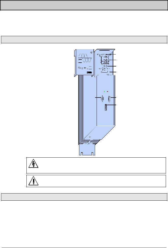
Start-up manual |
COMPAX-M / -S |
7.3Mains module NMD10/NMD20
The mains module ensures the supply of current to the COMPAX-M (not COMPAX 35XXM) axis controller and the SV drive connected into the network. It is connected to the 3-phase power supply with 3 * 400V AC and PE. 24V DC voltage must be provided for the control electronics.
7.3.1 Overview NMD
Power Supply
L1 |
L2 L3 PE |
24V |
|
PE |
+ - |
|
|
|
|
|
|
|
X1 |
|
|
|
|
|
|
|
|
|
|
|
PE |
|
|
|
PE |
|
|
|
|
|
|
|
|
|
|
||
|
|
|
|
|
|
|
X2 |
|
|
|
|
|
|
|
|
|
|
|
+LS |
|
|
|
+LS |
|
|
|
|
|
|
|
-LS |
+ |
|
+ |
-LS |
|
|
|
|
|
|
|
24V |
|
24V |
||
|
|
|
|
|
|
|
X3 |
|
|||
|
|
|
|
|
|
|
|
- |
|
- |
X4 |
|
|
|
|
|
|
|
|
|
|
|
|
|
|
|
|
|
|
|
|
|
|
|
|
|
|
|
|
|
|
|
|
|
|
|
|
|
|
|
|
|
|
|
|
|
|
|
|
voltage supply 3*(80-500)V AC/
X1 24V CC
X2 power intermediate loop
X3 control voltage 24 V
X4 controland status-signals Bus signals continuation
X6 bussystems IN
|
Ready Error |
|
|
X6 |
X7 |
X7 |
bus-systems |
|
|
||
IN |
RS 485 OUT |
|
OUT |
|
X8 |
X8 |
Control |
|
|
Control

 X18 fan
Before wiring up, always de-energize the unit.
Even once the mains supply has been switched off, dangerous levels of voltage can remain in the system for up to 5 min.
The PE connection must be a 10mm2 version
7.3.2 Dimensions / installation
Dimensions and installation of the NMD10 and NMD20 power units correspond to the data for COMPAX-M (see Page 20).
22

Mains module NMD10/NMD20
NMD connector assignment
7.3.3 NMD connector assignment
|
|
X1/1 |
L1 |
|
|
|
+24V |
X8/1 |
|
|
|
|
|
|
|
|
|
||||||
|
|
|
|
|
|||||||
|
|
|
|
|
X8/2 |
|
|||||
|
|
X1/2 |
|
|
|
|
|
||||
|
|
L2 |
|
|
|
GND |
|
|
|||
|
|
|
|
|
|
|
|||||
|
|
|
|
|
|
||||||
|
|
|
|
|
|
||||||
|
|
X1: |
|
|
X8/3 |
|
|||||
|
|
X1/3 |
|
|
|
|
|||||
|
|
L3 |
|
|
|
P |
|
|
|||
|
|
|
|
|
|
||||||
|
|
|
|
|
|
||||||
|
|
|
|
|
|
||||||
|
|
|
|
|
|
|
|||||
|
|
X1/4 |
voltage |
X8 |
stand by |
X8/4 |
|
|
|||
|
|
|
|
||||||||
|
|
PE |
supply |
|
|
|
S |
|
|
||
|
|
|
|
|
|
||||||
|
|
|
|
|
X8/5 |
|
|||||
|
|
X1/5 |
|
|
|
|
|
||||
|
|
|
|
|
|
|
|||||
|
|
+24V |
|
|
|
+24V |
|
|
|||
|
|
|
|
|
|
||||||
|
|
|
|
|
X8/6 |
|
|||||
|
|
X1/6 |
|
|
|
|
|
||||
|
|
|
|
|
|
|
|||||
|
|
0V |
|
15V-24 V emerg. stop |
|
|
|||||
|
|
|
|
||||||||
|
|
|
X8/6 |
|
|||||||
|
|
|
|
|
|
||||||
|
|
|
|
|
|
|
housing |
|
|
||
|
|
|
|
|
|
|
|
||||
|
|
|
|
|
|
|
|
||||
|
|
|
|
|
|
|
|
|
|||
|
|
X6: input bus systems |
X7: output bus systems |
|
|||||||
|
|
Assignment depends on the |
|
Assignment depends on the |
|
||||||
|
|
bus system |
|
|
bus system |
|
|
|
|
||
|
|
|
PEF |
X2: |
|
|
|
|
|
|
|
|
|
|
|
|
|
|
|
|
|
||
|
|
|
|
|
|
|
|
|
|
||
|
|
|
+LS |
power inter- |
X3: |
|
|
+24V |
|
|
|
|
|
|
|
|
|
|
|
||||
|
|
|
|
|
|
|
|
||||
|
|
|
-LS |
mediate loop |
Control |
|
0V |
|
|
|
|
|
|
|
|
|
|
|
|||||
|
|
|
|
|
|
|
|||||
|
|
|
|
|
voltage |
|
|
|
|
|
|
|
|
|
|
|
|
|
|
|
|
||
7.3.4 Technical data / power features NMD
Function
Generates DC current when run directly off a mains source.
CE conformity
!EMC immunity/emissions as per EN61800-3.
!Safety: VDE 0160/EN 50178.
Output power
|
Nominal power |
Peak power |
NMD10: |
10 kW |
20 kW (<3s) |
NMD20: |
20 kW |
40 kW (<3s) |
Mains fuse protection
NMD10: 16A (K circuit breaker in 20A)
NMD20: 35A
K circuit breaker or similar Neozed fusible cut-out.
Supply voltage up to max. 3*500V AC
!Operating range: 3*80V AC - 3*500V AC, 45 - 65 Hz.
Typical AC mains: 400V ± 10%; 460V ± 10%; 480V ± 5%
!Layout of contactors for the power supply:
Capacity according to device performance: Application group AC3.
Control voltage
!21.6V up to 26.4V DC (0.8A)
!Ripple: < 1VSS
!Fuse protection: max. 16A
Dissipation power
!without fan: max. 120W (standard)
!with fan: max. 250W.
23
Unit |
hardware |
|
|
Connector |
assignment / cable |
Technical data |
|
|
|
Configuration |
|
|
|
Positioning and |
control functions |
|
|
Optimization |
functions |
|
|
Interfaces |
|
|
|
Accessories / |
options |
|
|
Status |
|
|
|
Parameter |
|
|
|
Error list |
|
|
|
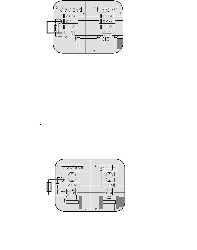
Start-up manual |
COMPAX-M / -S |
Activation of the internal ballast resistance for NMD20
Overvoltage limitation
Energy recuperated during braking is stored in the supply capacitors. The capacity and storable energy is:
NMD10/NMD20: 1100 F / 173 Ws
If the energy recuperated from braking causes overvoltage, then ballast resistances are engaged.
The internal ballast resistance is activated by a bridge between +LS and X5/1. In the NMD20 delivery status this bridge is fitted.
|
|
|
L1 L2 L3 PE 24V |
|
U |
V W PE Brake |
|||||||||||
|
|
|
|
+ - |
|
|
|
PE + - |
|||||||||
|
X1 |
|
|
|
|
|
|
|
X1 |
|
|
|
|
|
|||
|
|
X2 |
|
|
|
|
|
|
|
|
|
|
|
|
|
|
|
|
|
PE |
|
|
|
|
|
|
|
|
|
|
|
|
|
|
|
|
|
|
|
|
|
|
|
X2 |
|
|
|
|
|
||||
|
|
+LS |
|
|
|
|
|
|
|
|
|
|
|
||||
|
|
|
|
|
|
|
|
|
|
|
|
|
|
|
|
||
|
ext |
-LS |
|
|
|
|
|
|
|
|
|
|
|
|
|
|
|
|
int |
|
|
|
|
|
|
|
|
|
|
|
|
|
|
||
|
RB |
RB |
1 |
|
|
|
|
|
|
|
|
|
|
|
|
|
|
|
|
|
|
|
X3 |
|
X3 |
||||||||||
|
|
X5 |
|
|
|
||||||||||||
|
|
|
|
|
|
|
|
|
|
|
|
|
|
|
|
||
|
|
|
2 |
|
|
|
|
|
|
|
|
|
|
|
|
|
|
|
|
|
|
|
|
|
|
|
|
|
|
|
|
|
|
|
|
|
|
|
|
|
|
|
|
|
|
|
|
|
|
|
|
|
|
|
|
|
|
|
|
|
|
|
|
|
|
|
|
|
|
|
|
|
|
|
|
|
|
|
X4 |
|
|
X5 |
|
|
|
X4 |
|
||
Maximum braking |
Braking power |
Duration |
|
Cooling down time |
|
power: |
NMD10 |
|
|
|
|
|
17 kW |
<50 ms |
|
≥ |
10s |
|
4.0 kW |
<1s |
|
≥ |
50s |
|
Without fan: 120W |
|
|
unlimited |
|
|
With fan: 250W |
|
unlimited |
|
|
|
NMD20 |
|
|
|
|
|
9.5 kW |
<50 ms |
|
≥ |
10s |
|
2.5 kW |
<1s |
|
≥ |
50s |
|
Without fan: 120W |
|
|
unlimited |
|
|
With fan: 200W |
|
unlimited |
|
|
 External ballast resistances can be used with NMD20 (see Page 193).
Connecting the external ballast resistance
If the braking power of the internal ballast resistance is insufficient, an external ballast resistance can be connected.
The external ballast resistance is connected between +LS and X5/2. To do this, the bridge between +LS and X5/1 must be removed.
The full braking power cannot be used with this bridge present.
|
|
|
|
|
L1 L2 L3 PE 24V |
|
U V W PE Brake |
||||||||||||
|
|
|
|
|
|
+ - |
|
|
|
|
PE + - |
||||||||
|
|
|
X1 |
|
|
|
|
|
|
|
X1 |
||||||||
|
|
|
|
X2 |
|
|
|
|
|
|
|
|
|
|
|
|
|
|
|
|
|
|
|
PE |
|
|
|
|
|
|
|
|
|
|
|
|
|
|
|
|
|
|
|
|
|
|
|
|
|
X2 |
|||||||||
|
|
|
|
+LS |
|
|
|
|
|
|
|||||||||
|
|
|
|
|
|
|
|
|
|
|
|
|
|
|
|
|
|
||
|
|
|
|
-LS |
|
|
|
|
|
|
|
|
|
|
|
|
|
|
|
ext |
|
|
ext |
|
|
|
|
|
|
|
|
|
|
|
|
|
|
||
|
|
int |
|
|
|
|
|
|
|
|
|
|
|
|
|
|
|||
RB |
|
|
RB |
RB |
1 |
|
|
|
|
|
|
|
|
|
|
|
|
|
|
|
|
|
|
|
|
|
X3 |
|
X3 |
||||||||||
|
|
|
|
X5 |
|
|
|
||||||||||||
|
|
|
|
|
|
|
|||||||||||||
|
|
|
|
|
|
|
|
|
|
|
|
|
|
|
|
|
|
||
|
|
|
|
|
2 |
|
|
|
|
|
|
|
|
|
|
|
|
|
|
|
|
|
|
|
|
|
|
|
|
|
|
|
|
|
|
|
|
|
|
|
|
|
|
|
|
|
|
|
|
|
|
|
|
|
|
|
|
|
|
|
|
|
|
|
|
|
|
|
|
|
|
|
|
|
|
|
|
|
|
|
X4 |
X5 |
|
X4 |
Output X5 is protected from short circuits.
Thermal protection
An emergency stop is triggered at 85°C heat sink temperature, the ready contact is released and the red LED lights up.
24
|
|
|
|
|
|
|
Mains module NMD10/NMD20 |
|
|
|
|
|
|
|
|
||
|
|
|
|
|
|
|
||
|
|
|
|
|
|
|
|
|
|
|
|
|
|
|
|
Technical data / power features NMD |
|
|
|
|
|
|
If a phase malfunctions, no displays appear |
|||
|
|
Error diagnosis in |
|
|
|
|
||
|
|
LED red |
LED green |
Possible errors |
|
|||
|
|
the mains module |
Error |
Ready |
|
|
||
|
|
|
|
|
off |
on |
no errors |
|
|
|
|
|
|
on |
off |
! Heat sink temperature too high |
|
|
|
|
|
|
|
|
or |
|
|
|
|
|
|
|
|
! error in logic voltage (24V DC too low or unit is |
|
|
|
|
|
|
|
|
defective) |
|
|
|
|
|
|
|
|
Emergency stop is activated and ready |
|
|
|
|
|
|
|
|
contact is released. |
|
|
|
|
|
|
on |
on |
! Ballast switch overloaded |
|
|
|
|
|
|
|
|
or |
|
|
|
|
|
|
|
|
! undervoltage (<100V DC or <80V AC). |
|
 Ready contact and green LED are coupled.
Caution!
If the unit has no control voltage, no displays will indicate that operating voltage is present.
25
Unit |
hardware |
|
|
Connector |
assignment / cable |
Technical data |
|
|
|
Configuration |
|
|
|
Positioning and |
control functions |
|
|
Optimization |
functions |
|
|
Interfaces |
|
|
|
Accessories / |
options |
|
|
Status |
|
|
|
Parameter |
|
|
|
Error list |
|
|
|
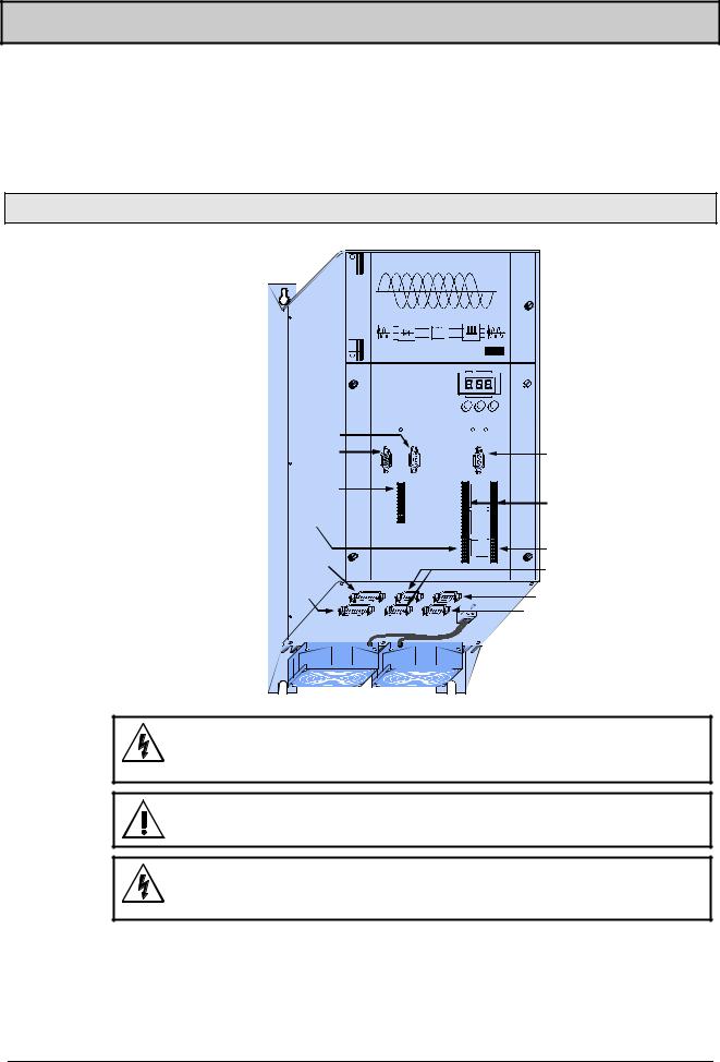
Start-up manual |
COMPAX-M / -S |
7.4COMPAX 35XXS unit features
The 35 kW servo control COMPAX 35XXM - a performance upgrade to the
COMPAX family.
!Compact unit with output currents of 50 Aeff / 100 Aeff (<5s) with integrated power unit.
!Additional COMPAX-M controllers of up to 15 KW can be arranged in rows.
7.4.1Plug and connection assignment COMPAX 35XXM
COMPAX-M |
|
|
|
|
|
|
|
|
Digital |
|
|
|
|
S ta tu s N u m b e r |
|
||
Bus |
|
|
Value |
|
|
|
|
|
|
|
|
systems: |
|
- |
+ |
E n te r |
|
H1 |
|
|
|
|
|
X7 OUT |
|
|
R eady E rro r |
|
|
|
|
X6 |
|
|
|
X5 |
X7 |
|
|
X6 RS232 |
|
X5 IN |
|
|
|
R S 2 3 2 |
|
IN |
|
OUT |
|
|
|
X19 |
X19 |
X8 |
|
X10 |
|
|
|
|
|
|
|
Control |
|
|
In p u t |
|
X8/X10 In-/ |
Control |
|
|
|
||
X9 Test |
|
|
|
|
Output |
|
|
O u tp u t |
|
|
|
X13 |
|
|
Test |
|
X11 Control |
|
|
C o n tro l |
|
||
Encoder |
|
X9 |
|
X11 |
X14/X15 |
X12 |
|
|
|
|
HEDA |
Resolver |
|
|
|
|
X17 Initiators |
|
|
|
|
|
|
|
|
|
|
|
X16 Absolute |
|
|
|
|
|
encoder |
Before wiring up, always de-energize the unit.
Even once the mains supply has been switched off, dangerous levels of voltage can remain in the system for up to 5 min.
When working with motors without a holding brake, the brake lines must not be connected to COMPAX
Caution!
If the unit has no control voltage, no displays will indicate that operating voltage is present.
26
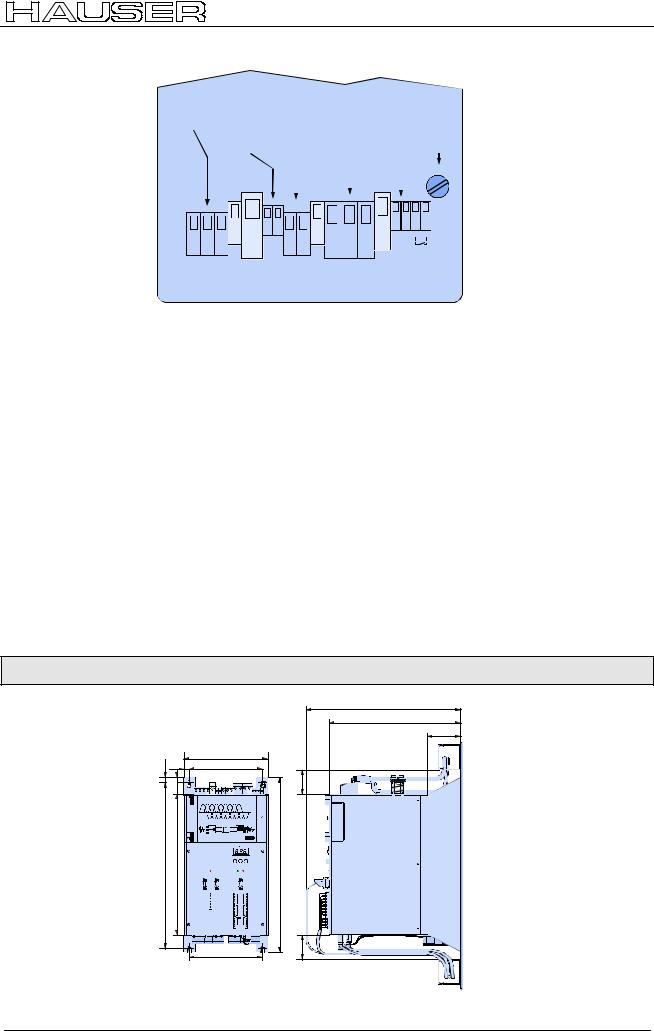
COMPAX 35XXS unit features
Installation and dimensions of COMPAX 35XXM
Plan view
AC - voltage |
|
|
|
|
|
|
|
|
|
|
|
|
external |
|
|
|
|
|
|
|
|
|
|
|
|
|
|
|
|
|
|
|||||||||||||||
up to 500V AC |
|
|
|
|
|
|
|
|
|
|
|
|
|
ballast |
|
|
|
|
|
|
|
|
|
|
motor |
|||||||||||||||||||||
|
|
|
|
|
|
|
|
|
|
|
|
|
|
|
|
|
|
resistor |
|
|
|
|
|
|
|
|
|
|
brake |
|||||||||||||||||
|
|
|
|
|
|
24V control |
|
|
|
motor |
|
|
|
|
|
|
|
|
|
F1 |
||||||||||||||||||||||||||
|
|
|
|
|
|
|
|
voltage |
|
|
|
|
|
|
|
|
|
|
|
|
3.16A |
|||||||||||||||||||||||||
|
|
|
|
|
|
|
|
|
|
|
|
|
|
|
|
|
|
|
|
|
|
|
|
|
|
|
|
|
|
|
|
|
|
|
|
|
|
|
|
|
|
|
|
|
|
F1 |
|
|
|
|
|
|
|
|
|
|
|
|
|
|
|
|
|
|
|
|
|
|
|
|
|
|
|
|
|
|
|
|
|
|
|
|
|
|
|
|
|
|
|
|
|
|
|
|
|
|
|
|
|
|
|
|
|
|
|
|
|
|
|
|
|
|
|
|
|
|
|
|
|
|
|
|
|
|
|
|
|
|
|
|
|
|
|
|
|
|
|
|
|
|
|
|
|
|
|
|
|
|
|
|
|
|
|
|
|
|
|
|
|
|
|
|
|
|
|
|
|
|
|
|
|
|
|
|
|
|
|
|
|
|
|
|
|
|
|
|
|
|
|
|
|
|
|
|
|
|
|
|
|
|
|
|
|
|
|
|
|
|
|
|
|
|
|
|
|
|
|
|
|
|
|
|
|
|
|
|
|
|
|
|
|
|
|
|
|
|
|
|
|
|
|
|
|
|
|
|
|
|
|
|
|
|
|
|
|
|
|
|
|
|
|
|
|
|
|
|
|
|
|
|
|
|
|
|
|
|
|
|
|
|
|
|
|
|
|
|
|
|
|
|
|
|
|
|
|
|
|
|
|
|
|
|
|
|
|
|
|
|
|
|
|
|
|
|
|
|
|
|
|
|
|
|
|
|
|
|
|
|
|
|
|
|
|
|
|
|
|
|
|
|
|
|
|
|
|
|
|
|
|
|
|
|
|
|
|
|
|
|
|
|
|
|
|
|
|
|
|
|
|
|
|
|
|
|
|
|
|
|
|
|
+ - |
|
|
|
|
+ - |
|
|
|
PE |
|
|
PE |
|
|
PE |
|
|
L1 |
L2 L3 |
|
DC - In |
Braking |
U |
V |
W |
Motor |
|
|
Mains Input |
PE |
24 V |
Resistance |
|
Motor |
|
Brake |
||
|
|
X 20 |
|
X 21 |
X 22 |
|
X 1 |
|
X 23 |
|
|
|
|
|
|
|
|
|
|
|
|
Specific technical |
Supply voltage up to max. 3 * 500V AC |
data |
Operating range: 3*80V AC - 3*500V AC; 45 - 65 Hz. |
|
Typical AC mains: 400V ± 10%; 460V ± 10%;480V ± 5% |
|
! Layout of contactors for the power supply: |
|
Capacity according to device performance: Application group AC3 |
|
Switching on the operating voltage for a second time: |
Note! |
|
|
Before switching on the operating voltage for a second time, you must wait for at |
|
|
|
least 2.5 minutes otherwise you may overload the condenser load resistance. |
|
Control voltage |
|
! 21.6V to 26.4V DC • Ripple: < 1VSS • fuse protection: max. 16A |
|
Mains supply fuse protection |
|
62A K circuit breaker or suitable Neozed conventional fuse. |
|
Regeneration mode |
!Storable energy: 3450µF/542 Ws
!External ballast resistance: 10Ω /2 kW
For the external ballast resistors available, please see Page 193.
7.4.2Installation and dimensions of COMPAX 35XXM
10 |
14 |
218 |
190 |
||
|
38 |
|
|
|
COMPAX-M |
430 |
363 |
|
|
|
|
|
|
|
|
|
|
450 |
|
|
|
|
|
|
|
|
|
|
|
|
|
|
|
|
|
|
|
|
|
|
|
|
|
|
|
|
|
|
|
|
|
|
|
|
|
|
|
|
|
|
|
|
|
|
|
|
|
|
|
|
|
|
|
|
|
190 |
390 |
340 |
86 |
65 |
65 |
Fastening with 4 M6 hex-socket head screws.
27
Unit |
hardware |
|
|
Connector |
assignment / cable |
Technical data |
|
|
|
Configuration |
|
|
|
Positioning and |
control functions |
|
|
Optimization |
functions |
|
|
Interfaces |
|
|
|
Accessories / |
options |
|
|
Status |
|
|
|
Parameter |
|
|
|
Error list |
|
|
|
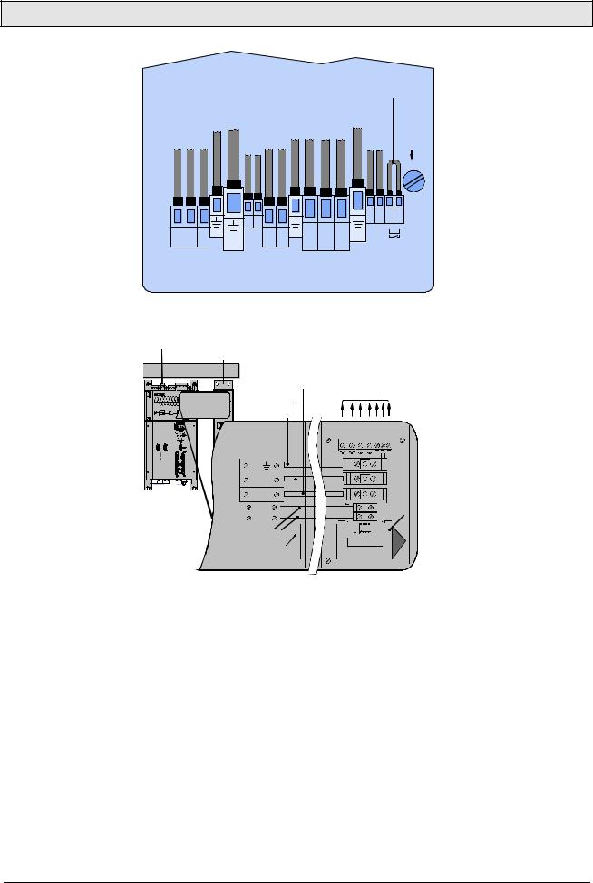
Start-up manual |
COMPAX-M / -S |
7.4.3 Wiring COMPAX 35XXM
Wiring up motor, mains power / control voltage and external ballast resistance
Wiring up system network
|
Supply up to 500V AC |
yellow/green |
yellow/green |
Control voltage |
External |
brakingresistance |
PE |
U |
V |
W |
yellow/green |
Motor4black brake*5black |
F1 |
|
|
|
|
|
|
1 black |
2 black |
3 black |
|
||||||
|
|
|
|
|
|
|
|
|
|
|
|
|
Connection for |
|
|
|
|
|
|
|
|
|
|
|
|
|
|
external contact |
|
|
|
|
|
|
|
|
|
|
|
Motor |
|
|
for brake control |
|
|
|
|
PE |
PE |
24V |
|
|
|
|
|
|
|
|
|
|
L1 |
L2 L3 |
|
|
|
|
|
|
|
|
|
3.16A |
||
|
|
|
|
|
+ - |
|
|
|
|
|
|
|
|
|
|
|
|
|
|
|
|
|
|
|
|
|
|
|
F1 |
|
|
|
|
|
4 5 |
|
|
|
|
|
|
|
111213 14 |
|
|
|
|
|
|
|
|
|
|
|
|
|
+ - |
|
|
|
1 |
2 |
3 |
|
|
6 |
7 |
|
8 |
9 |
10 |
|
|
|
|
|
|
|
|
|
|
||||||||
|
|
|
PE |
|
+ - |
|
|
PE |
|
|
|
PE |
|
|
|
L1 |
L2 |
L3 |
|
DC - In |
Braking |
|
U |
V |
W |
|
Motor |
|
|
|
Mains Input |
|
24 V |
Resistance |
|
|
Motor |
|
|
Brake |
|
|||
|
|
X 20 |
|
|
X 21 |
|
X 22 |
|
|
X 1 |
|
|
X 23 |
|
* |
max. 1.6A |
|
|
|
|
|
|
|
|
|
|
|
||
The PE connection must be a version of at least 10mm2
COMPAX 35XXM |
|
|
COMPAX-M / SV-M |
|
|
Cable conduit |
|
|
... |
LS- |
Motor |
HAUSER |
LS+ |
|
|
|
|
|
|
|
|
|
|
|
|
|
|
|
|
|
PE |
|
|
|
|
|
|
|
|
|
CO MP AX -M |
|||||
|
|
|
|
|
|
|
|
|
|
|
|
|
|
U V W PE Brake |
|
|
|
|
|
|
|
|
|
|
|
|
|
|
|
|
|
|
|
|
|
|
|
|
|
|
|
|
|
|
|
|
|
|
|
|
|
|
|
|
|
|
|
|
PE+ - |
|
|
|
|
|
|
|
|
|
|
|
|
|
|
X1 |
|
|
|
|
|
|
|
|
... |
|
|
|
|
|
|
|
|
|
|
|
|
|
|
|
|
|
|
|
|
|
|
||||
|
|
|
|
|
|
|
|
|
|
|
|
|
|
|
|
|
|
|
|
|
|
|
|
|
|
|
|
|
|
|||||
|
|
|
|
|
|
|
|
|
|
|
|
|
|
|
|
|
|
|
|
|
|
|
|
|
||||||||||
|
|
|
|
|
|
|
|
|
|
|
|
|
|
|
|
|
|
|
|
18 |
|
|
|
|
X2 |
|
|
|
|
|
|
|||
|
|
|
|
|
|
|
|
|
|
|
|
|
|
|
|
|
|
|
|
|
|
|
|
|
|
|
|
|
||||||
|
|
|
|
|
|
|
|
|
|
|
|
|
|
|
|
|
|
|
|
|
|
|
|
|
|
|
|
|
|
|
|
|
|
|
|
|
|
|
|
|
|
|
|
|
|
|
|
|
|
|
|
|
|
|
17 |
|
|
|
|
|
|
|
|
|
|
|
|
|
|
|
|
|
|
|
|
|
|
|
|
|
|
|
|
|
|
|
|
|
|
|
|
|
|
|
|
|
|
|
|
|
|
|
|
|
|
|
|
|
|
|
|
|
|
|
|
|
|
|
|
|
|
|
|
|
|
|
|
|
|
|
|
|
|
|
|
Last device |
|||
|
|
|
|
|
|
|
|
|
|
|
|
|
|
|
|
|
|
|
|
16 |
|
|
|
|
|
|
|
|
|
|
|
equiped with |
||
+ |
|
|
|
|
|
|
|
|
|
|
|
|
|
terminal plug |
||||||||||||||||||||
|
|
|
|
|
X3 |
|||||||||||||||||||||||||||||
|
|
|
|
|
|
|
|
|
|
|
|
|
|
24V - |
|
|
15 |
|
|
|
|
|
|
|
|
|
|
|
|
|
|
|||
|
|
|
|
|
|
|
|
|
|
|
|
|
|
|
|
|
|
|
|
|
|
|
|
|
|
|
|
|||||||
|
|
|
|
|
|
|
|
|
|
|
|
Voltage supply 24V |
|
|
|
|
|
|
|
|
|
|
|
|||||||||||
|
|
|
|
|
|
|
|
|
|
|
|
|
|
|
|
|
|
|
|
|
|
|
||||||||||||
|
|
|
|
|
|
|
|
|
|
|
|
|
Emergency stop, |
|
|
|
|
|
|
|
|
|
|
|
||||||||||
|
|
|
|
|
|
|
|
|
|
|
|
|
stand by and |
|
|
|
|
|
|
|
|
|
|
|
||||||||||
|
|
|
|
|
|
|
|
|
|
|
|
|
bus signals |
|
|
|
|
|
|
|
|
|
||||||||||||
|
|
|
|
|
|
|
|
|
|
|
|
|
|
|
X5 |
X4 |
||||||||||||||||||
28
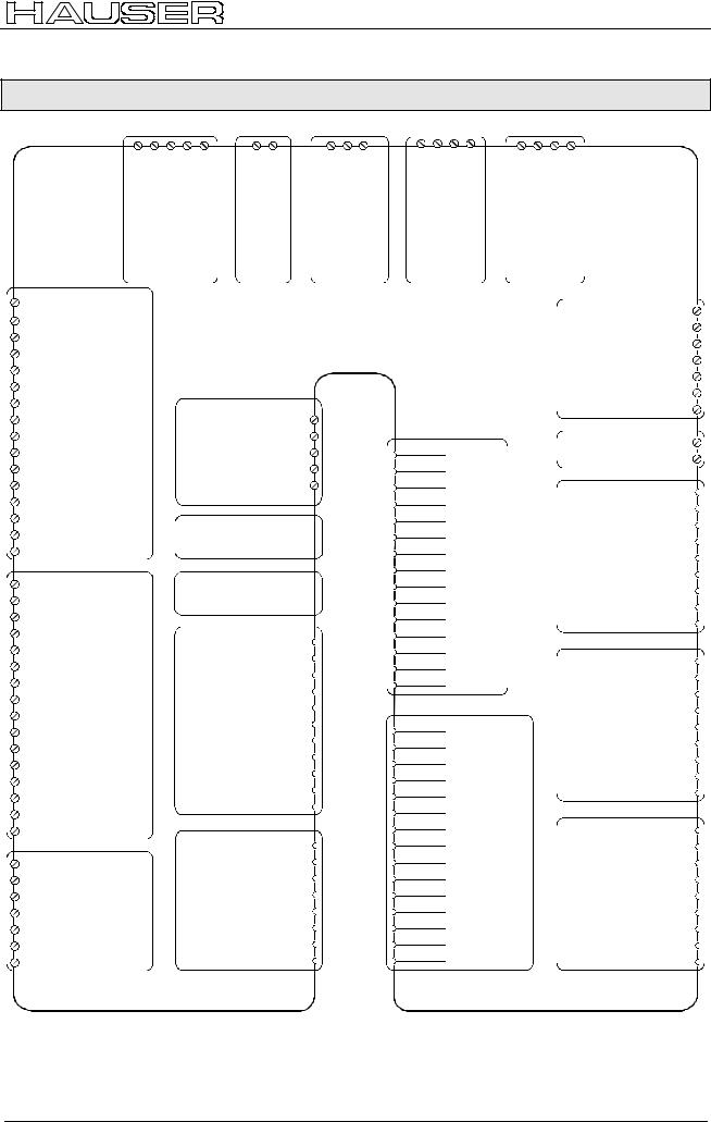
COMPAX 35XXS unit features
COMPAX 35XXM connector assignment
7.4.4 COMPAX 35XXM connector assignment
|
|
|
|
|
|
|
|
|
|
|
|
|
|
|
|
|
|
|
|
|
|
|
|
|
|
|
|
|
|
|
|
|
|
|
|
|
|
|
|
|
|
|
|
|
|
|
|
|
|
|
|
|
|
|
|
|
|
|
|
|
|
|
|
|
|
|
|
|
|
|
|
|
|
|
|
|
|
|
|
|
|
|
|
|
|
|
|
|
|
|
|
|
|
|
|
|
|
|
|
|
|
|
|
|
|
|
|
|
|
|
|
|
|
|
|
|
|
|
|
|
|
|
|
|
|
|
|
|
|
|
|
|
|
|
X1/1 |
|
X1/2 |
|
X1/3 |
|
|
|
X23/1 |
|
X23/2 |
|
|
|
|
|||||||||
|
|
|
|
|
|
|
|
|
|
|
|
PE |
|
|
|
|
|
|
|
|
|
|
|
|
|
|
|
U |
|
V |
|
W PE |
|
Br'+ |
|
Br- |
||||||||||||||||
X20: |
|
|
|
|
|
|
|
|
|
|
|
|
|
|
|
X1: |
|
|
|
|
|
|
X23: |
|||||||||||||||||||||||||||||
AC Supply |
|
|
|
|
|
|
|
|
|
|
|
|
|
|
|
|
|
|
|
|
|
|||||||||||||||||||||||||||||||
|
|
|
|
|
|
|
|
|
|
|
|
|
|
|
|
|
|
|
|
|
|
|
|
|
|
|
|
|
|
Motor |
Motor brake |
|||||||||||||||||||||
|
|
|
|
X8: Input/ output |
...I8;I1O1...O8 |
24VanddcHV additionalfor M-COMPAX |
|
PE |
|
|
|
|
|
|
|
|
|
|
|
|
|
|
|||||
|
|
|
|
|
|
|
|
|
|||||
|
|
|
|
|
|
|
|
|
|||||
|
|
|
|
|
|
|
|
|
|||||
|
|
|
|
|
|
|
|
|
|||||
|
|
|
|
|
|
|
|
|
|||||
|
|
|
|
|
|
|
|
|
|||||
|
|
|
|
|
|
|
|
|
|||||
|
|
|
|
|
|
|
|
|
|||||
|
|
|
|
|
|
|
|
|
|||||
|
|
|
|
|
|
|
|
|
|||||
|
|
|
|
|
|
|
|
|
|||||
|
|
|
|
|
|
|
|
|
|||||
|
|
|
|
|
|
|
|
|
|||||
|
|
|
|
|
|
|
|
|
|||||
|
|
|
|
|
|
|
|
|
|||||
|
|
|
|
|
|
|
|
|
|||||
|
|
|
|
|
|
|
|
|
|||||
|
|
|
|
|
|
|
|
|
|||||
|
|
|
|
|
|
|
|
|
|||||
|
|
|
|
|
|
|
|
|
|||||
|
|
|
|
|
|
|
|
|
|
|
|
||
|
|
|
|
|
|
|
|
+LS |
|
|
|
|
|
|
|
|
|
|
|
|
|
|
|
|
|
||
|
|
|
|
|
|
|
|
|
|
|
|
||
|
|
|
|
|
|
|
|
-LS |
|
|
|
|
|
|
|
|
|
|
|
|
|
|
|
|
|
||
|
|
|
|
|
|
|
|
|
|
|
|
||
|
|
|
|
|
|
|
|
+24V |
|
|
|
|
|
|
|
|
|
|
|
|
|
|
|
|
|
||
|
|
|
|
|
|
|
|
|
|
|
|
||
|
|
|
|
|
|
|
|
0V |
|
|
|
|
|
|
|
|
|
|
|
|
|
|
|
|
|
||
|
|
|
|
|
|
|
|
|
|
|
|
||
|
|
|
|
|
|
X7: output bus systems |
|
|
|
||||
|
|
|
|
|
|
|
|
|
|||||
|
|
|
|
|
|
|
|
|
|||||
|
|
|
|
|
|
|
|
|
|||||
|
|
|
|
|
|
|
|
|
|||||
|
|
|
|
|
|
|
|
|
|||||
|
|
|
|
|
|
|
|
|
|||||
|
|
|
|
|
|
|
|
|
|||||
|
|
|
|
|
|
Assignment depends on |
|
|
|
||||
|
|
|
|
|
|
|
|
|
|||||
|
|
|
|
|
|
the bus system |
|
|
|
|
|||
|
|
|
|
|
|
|
|
|
|
||||
|
|
X10/1 |
I9 |
|
|
X5: output bus systems |
|
|
|
||||
|
|
|
|
|
|
|
|||||||
|
|
|
|
|
|
||||||||
|
|
|
|
|
|
|
|
||||||
|
|
X10/2 |
I10 |
|
|
Assignment depends on |
|
|
|
||||
|
|
|
|
|
|
||||||||
|
|
|
|
|
|
|
|||||||
|
|
|
|
|
the bus system |
|
|
|
|
||||
|
|
X10/3 |
|
|
|
|
|
|
|||||
|
|
I11 |
|
|
|
|
|
|
|
|
|
|
|
|
|
|
|
|
|
|
|
|
|
|
|
||
|
|
X10/4 |
|
|
|
|
|
|
|
|
|
|
|
|
|
I12 |
|
|
|
|
+24V |
X19/1 |
|
|
|
||
|
|
|
|
|
|
|
|
|
|||||
|
|
X10/5 |
|
...I16;I9O9...O16 |
|
|
|
|
|
||||
|
|
I13 |
|
|
|
|
|
|
|||||
|
|
|
|
|
X19/2 |
|
|
|
|||||
|
|
X10/6 |
X10: /Inputoutput |
|
|
GND |
|
|
|
||||
|
|
O10 |
|
|
|
|
|
||||||
|
|
|
|
|
|
|
|
||||||
|
|
X10/10 |
|
|
|
|
|
|
|
|
|||
|
|
X10/7 |
I14 |
|
|
Stand by P |
X19/3 |
|
|
|
|||
|
|
X10/8 |
I15 |
|
|
Stand by S |
X19/4 |
|
|
|
|||
|
|
I16 |
|
|
X19/5 |
|
|
|
|||||
|
|
X10/9 |
|
|
|
|
+24V |
|
|
|
|||
|
|
O9 |
|
|
|
|
|
|
|
||||
|
|
|
|
|
|
X19/6 |
|
|
|
||||
|
|
|
|
|
15-24V Emerg.stop |
|
|
|
|
||||
|
|
|
|
|
|
|
|
|
|
||||
|
|
|
|
|
|
|
X19/7 |
|
|
|
|||
|
|
|
|
|
|
|
|
|
|||||
|
|
X10/11 |
O11 |
|
|
X19 |
|
24V |
|
|
|
||
|
|
|
|
|
|
|
|
||||||
|
|
|
|
|
X19/8 |
|
|
|
|||||
|
|
X10/12 |
|
|
reserved |
|
|
|
|||||
|
|
O12 |
|
|
|
|
|
||||||
|
|
|
|
X19/9 |
|
|
|
||||||
|
|
X10/13 |
|
|
|
|
+24V |
|
|
|
|||
|
|
|
O13 |
|
|
|
|
Enable |
X19/10 |
|
|
|
|
|
|
X10/14 |
|
|
|
|
|
|
|
||||
|
|
O14 |
|
|
|
|
X19/11 |
|
|
|
|||
|
|
X10/15 |
|
|
|
|
Shield |
|
|
|
|||
|
|
O15 |
|
|
|
|
|
|
|
||||
|
|
|
|
|
|
|
|
|
|
||||
|
|
X10/16 |
|
|
|
|
|
|
|
|
|
|
|
|
|
O16 |
|
|
|
|
RxD |
X6/2 |
|
|
|
||
|
|
|
|
|
|
|
|
|
|||||
|
|
|
|
|
|
|
|
|
|
||||
|
|
|
|
|
|
|
|
|
|
|
|||
|
|
|
|
|
|
|
|
|
|
|
|||
|
|
X9/1 |
|
|
|
|
|
X6/3 |
|
|
|
||
|
|
+24V |
|
|
|
|
TxD |
|
|
|
|||
|
|
|
|
|
|
|
|
|
|||||
|
|
|
|
|
|
|
|
|
|||||
|
|
|
|
|
|
|
X6/4 |
|
|
|
|||
|
|
X9/2 |
|
|
|
|
|
|
|
||||
|
|
GND |
|
X9 |
X6: RS232 |
DTR |
|
|
|
||||
|
|
|
|
|
|
||||||||
|
|
|
|
|
|
||||||||
|
|
|
|
|
|
||||||||
|
|
|
|
X6/6 |
|
|
|
||||||
|
|
X9/4 |
|
|
|
|
|||||||
|
|
reserved |
DSR |
|
|
|
|||||||
|
|
X9/3 |
reserved |
|
|
|
GND |
X6/5 |
|
|
|
||
|
|
|
|
|
|
|
|
|
|
|
|
|
|
|
|
|
|
|
|
|
|
|
|
|
|
|
|
|
|
|
|
|
|
|
|
|
|
|
|
|
|
|
|
|
|
|
|
|
|
|
|
|
|
|
|
|
|
|
|
|
|
|
|
|
|
X6/7 |
|
|
|
|
|
X9/5 |
24V |
|
|
|
|
RTS |
|
|
|
||
|
|
|
|
|
|
|
|
|
|||||
|
|
|
|
|
|
|
|
|
|||||
|
|
|
|
|
|
|
|
|
|||||
|
|
|
|
|
|
|
|
|
|||||
|
|
|
|
|
|
|
X6/8 |
|
|
|
|||
|
|
X9/6 |
|
|
|
|
|
|
|
||||
|
|
15-24V Emerg. stop* |
|
|
CTS |
|
|
|
|||||
|
|
|
|
|
|
|
|||||||
|
|
|
|
|
|
|
|||||||
|
|
|
|
|
|
|
|||||||
|
|
|
|
|
|
|
|||||||
|
|
|
|
|
X6/9 |
|
|
|
|||||
|
|
X9/7 |
|
|
|
|
|
||||||
|
|
Housing |
|
|
|
+5V |
|
|
|
||||
|
|
|
|
|
|
|
|
||||||
|
|
|
|
|
|
|
|
||||||
|
|
|
|
|
|
|
|
||||||
|
|
|
|
|
|
|
|
|
|
||||
|
|
|
|
|
|
|
|
|
|
||||
|
|
|
|
|
|
|
|
|
|
|
|
|
|
* can be parameterized
Enable final stage
X12/1
X12/2
X12/3
X12/4
X12/5
X12/6
X12/7
X12/8
X12/9
X12/10
X12/11
X12/12
X12/13
X12/14
X12/15
X13/1
X13/2
X13/3
X13/4
X13/5
X13/6
X13/7
X13/8
X13/9
X13/10
X13/11
X13/12
X13/13
X13/14
X13/15
Housing +8V NC REFSIN- NC GND ST+
+5 V
TEMP
COS-
COS+
SIN+
REF+
ST-
Housing N2
B2
A2
N1
B1
A1
+5V
N2/
B2/
A2/
N1/
B1/
A1/
GND
X12: Resolver / SinCos
X13: Encoder
|
|
|
+24V |
X11/1 |
|
|
|
|
|
X11/2 |
|||
|
|
|
GND |
|
||
|
|
|
X11/3 |
|||
|
|
Override |
||||
X11 |
|
X11/4 |
|
|||
DA-channel 2 |
|
|||||
X11/5 |
||||||
DA-channel 3 |
|
|||||
|
|
|||||
|
X11/6 |
|||||
|
Override (old) |
|
||||
|
X11/7 |
|||||
|
|
|
Shield |
|
||
|
|
|
X18/+ |
|||
X18: |
Fan |
|
24V |
|||
|
X18/- |
|
||||
|
0V |
|
||||
|
|
|||||
D1) |
DA-channel 0 |
X17/1 |
||||
X17/2 |
||||||
(Option |
DA-channel 1 |
|||||
X17/3 |
||||||
|
|
Shield |
||||
DAX17:-monitor |
|
|
X17/4 |
|||
|
GND 24V |
|||||
initiators |
X17/9 |
|||||
|
Sig. E1 |
|||||
|
|
|
+24V |
X17/5 |
||
|
|
|
GND |
X17/6 |
||
|
|
|
Sig.MN |
X17/7 |
||
|
|
|
X17/8 |
|||
|
|
|
Sig. E2 |
|||
|
|
|
|
|
||
|
|
|
|
|
|
|
|
|
|
NC X14(15)/1 |
|||
|
|
|
RxC X14(15)/2 |
|||
X14/X15: |
|
|
TxC X14(15)/3 |
|||
HEDA |
|
RxD X14(15)/4 |
||||
|
RxC/ |
X14(15)/6 |
||||
|
|
|
TxD |
X14(15)/5 |
||
|
|
|
TxC/ X14(15)/7 |
|||
|
|
|
RxD/ X14(15)/8 |
|||
|
|
|
TxD/ X14(15)/9 |
|||
|
|
|
T- |
X16/1 |
||
|
|
|
X16/2 |
|||
|
|
|
NC |
|||
|
|
|
X16/3 |
|||
|
|
|
D- |
|||
|
Absolute |
encoder |
X16/4 |
|||
|
NC |
|||||
X16: |
GND |
X16/5 |
||||
|
|
|
X16/6 |
|||
|
|
|
T+ |
|||
|
|
|
X16/7 |
|||
|
|
|
NC |
|||
|
|
|
X16/8 |
|||
|
|
|
D+ |
|||
|
|
|
X16/9 |
|||
|
|
|
+24V |
|||
|
|
|
|
|
||
The assignment of X12 does not apply for the S3 option.
29
Unit |
hardware |
|
|
Connector |
assignment / cable |
Technical data |
|
|
|
Configuration |
|
|
|
Positioning and |
control functions |
|
|
Optimization |
functions |
|
|
Interfaces |
|
|
|
Accessories / |
options |
|
|
Status |
|
|
|
Parameter |
|
|
|
Error list |
|
|
|
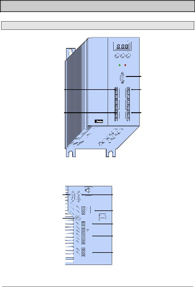
Start-up manual |
COMPAX-M / -S |
7.5COMPAX 25XXS unit characteristics
7.5.1 COMPAX 25XXS connector and connection assignment
COMPAX-S
X8 input / output
X9 test
Status Number
Value
-+ Enter
Ready |
Error |
|
|
X6 |
|
|
|
|
RS 232 |
X6 |
RS232 |
|
|
|
|
X8 |
X10 |
X10 digital input |
|
|
|
||
Input |
|
and output |
|
|
|
||
Output |
|
|
|
Test |
|
X11 control |
|
Control |
|
|
|
X9 |
X11 |
|
|
X12 resolver 


 X13 encoder X14 HEDA


 X15 HEDA X16 absolute


 X17 initiators
X18 fan


Meaning of the LEDs on the front plate
Plan view of COMPAX 25XXS
LED / color |
|
Meaning, when switched on |
|||||||||
Ready / green |
|
24V DC present and initialization complete |
|||||||||
Error / red |
|
COMPAX - fault (E1...E56) present. |
|||||||||
|
|
|
|
|
L1 |
2 |
L3 |
linetovoltage |
|
|
|
|
|
|
|
|
L2 AC230V+10% |
|
|
||||
|
|
|
|
|
|
AC |
|
|
|
|
|
|
|
|
|
|
0V |
|
|
|
|
|
|
|
|
|
|
|
23 |
230VAC |
|
|
|
|
|
|
|
|
|
|
C |
|
|
|
|
||
|
|
|
|
|
AV |
|
|
|
|
Bus systems |
|
X5 Bus |
|
|
|
|
|
03 |
|
|
|
X7 |
|
|
|
|
|
AC ! |
AC max. |
line |
|||||
|
|
|
|
|
|
OUT |
|||||
systems IN |
|
|
|
|
|
||||||
|
|
|
3 x 230V |
|
1 x 230V |
|
|
|
|||
|
|
|
X2/ |
|
|
|
|
||||
|
|
|
|
|
|
|
|
|
AC |
||
|
|
4 |
|
PE PE |
|
||||||
|
|
3 |
|
L3 |
|
N |
X2 |
supply |
|||
|
|
2 |
|
L2 |
|
||||||
|
|
1 |
|
L1 |
|
L |
|
|
|||
F19 |
|
|
|
|
|
|
|
|
|
|
|
3.16 AT |
|
X3/ |
|
|
|
|
|
X3 |
24V DC |
||
|
|
2 |
|
- |
|
|
|
||||
|
|
1 |
|
+ |
|
|
|
|
supply |
||
|
|
|
X1/ |
|
|
|
|
|
|
||
|
|
|
|
|
|
|
|
|
|
||
|
|
8 |
|
|
|
|
|
|
|
||
|
|
7 |
|
- |
|
|
|
|
|
||
|
|
6 |
|
|
|
|
X1 |
motor and |
|||
|
|
4 |
|
PE |
|
|
|
||||
|
|
5 |
|
+ |
|
|
|
|
|
||
|
|
3 |
|
W |
|
|
|
|
motor brake |
||
|
|
2 |
|
V |
|
|
|
|
|
||
|
|
1 |
|
U |
|
|
|
|
|
||
|
|
|
X4/ |
|
|
|
|
|
|
|
|
|
|
3 |
|
PE |
|
|
|
X4 |
braking |
||
|
|
2 |
|
B - |
|
|
|
||||
|
|
1 |
|
B+ |
|
|
|
|
resistance |
||
|
|
|
|
|
|
|
|
|
|
|
|
30
Loading...