

COMPAX-M /-S (L)
COMPAX User Guide
Compact Servo Controller
From software version V6.26 October 2001
Parker Hannifin GmbH
D
EMD Hauser
P. O. Box: 77607-1720
Robert-Bosch-Str. 22
D-77656 Offenburg, Germany
M
E
Phone: +49 (0)781 509-0
T
Fax: +49 (0)781 509-176
We automate motion
R
E
C
DIN EN ISO 9001
Q
U
A
L
I
T
Reg. Nr. 36 38
I
T
F
I
E
S
Y
Y
S
http://www.parker-emd.com
Subject to technical modification. 11.10.01 11:01 192-040053 N2
Data correspond to the state of technical development at the time of printing.
Parker Hannifin plc
Electromechanical Division
21 Balena Close
Poole, Dorset
BH17 7DX UK
Phone: +44 (0)1202 69 9000
Fax: +44 (0)1202 69 5750
http://www.parker-emd.com

Contents
COMPAX-M / -S
1. Contents
1. Contents...................................................................................................2
2. Un i t a s s i g n m e n t : ....................................................................................7
3. Sa f e t y i n s t r u c t i o n s.................................................................................8
3.1 General dangers........................................................................................8
3.2 Safe working practices.............................................................................8
3.3 Special safety instructions.......................................................................8
3.4 Conditions of warranty.............................................................................9
4. COMPAX – CD...........................................................................................9
5. Sw i t c h - o n s t a t u s...................................................................................10
5.1 Configuration when supplied.................................................................10
5.2 Commissioning .......................................................................................10
5.3 Equipment replacement..........................................................................12
6. Co n d i t i o n s f o r u s a g e ...........................................................................13
7. St a r t - u p m a n u a l ....................................................................................14
7.1 Overview: .................................................................................................14
7.1.1 Components required....................................................................................... 14
7.1.2 Overview of unit technology............................................................................ 15
7.2 COMPAX-M unit features........................................................................17
7.2.1 Connector and terminal assignment............................................................... 17
7.2.2 COMPAX-M system network, NMD10 / NMD20 mains module...................... 18
7.2.3 COMPAX-M dimensions/installation ............................................................... 20
7.2.4 Connector assignment COMPAX-M ................................................................ 21
7.3 Mains module NMD10/NMD20................................................................22
7.3.1 Overview NMD................................................................................................... 22
7.3.2 Dimensions / installation.................................................................................. 22
7.3.3 NMD connector assignment............................................................................. 23
7.3.4 Technical data / power features NMD.............................................................. 23
7.4 COMPAX 35XXS unit features................................................................26
7.4.1 Plug and connection assignment COMPAX 35XXM....................................... 26
7.4.2 Installation and dimensions of COMPAX 35XXM........................................... 27
7.4.3 Wiring COMPAX 35XXM.................................................................................... 28
2

7.4.4 COMPAX 35XXM connector assignment ........................................................ 29
7.5 COMPAX 25XXS unit characteristics ....................................................30
7.5.1 COMPAX 25XXS connector and connection assignment.............................. 30
7.5.2 COMPAX 25XXS-specific technical data......................................................... 32
7.5.3 COMPAX 25XXS dimensions / installation ..................................................... 33
7.5.4 Connector assignment COMPAX 25XXS ........................................................ 34
7.6 COMPAX 45XXS/85XXS unit characteristics........................................35
7.6.1 Plug and connection assignment COMPAX 45XXS/85XXS........................... 35
7.6.2 COMPAX 45XXS/85XXS installation / dimensions ......................................... 36
7.6.3 COMPAX 45XXS/85XXS-specific wiring.......................................................... 37
7.6.4 COMPAX 45XXS/85XXS connector and pin assignment............................... 39
7.7 COMPAX 1000SL Unit characteristics...................................................40
7.7.1 Connector and terminal assignment for COMPAX 1000SL........................... 40
7.7.2 Connector assignment COMPAX 1000SL (overview) .................................... 42
7.7.3 Mounting and dimensions COMPAX 1000SL ................................................. 43
7.7.4 Safety chain / emergency stop functions ....................................................... 44
7.8 Connections to the motor.......................................................................46
7.8.1 Resolver / SinCos.............................................................................................. 46
7.8.2 Additional brake control................................................................................... 51
7.9 Interfaces .................................................................................................52
7.9.1 Digital inputs and outputs (excluding COMPAX 1000SL).............................. 52
7.9.2 Digital inputs and outputs for COMPAX 1000SL............................................ 53
7.9.3 Technical data / Connections of inputs and outputs..................................... 54
7.9.4 Initiators and D/A monitor................................................................................ 55
7.9.5 Service D/A monitor / override......................................................................... 56
7.9.6 Service D/A monitor.......................................................................................... 56
7.9.7 D/A monitor option D1...................................................................................... 58
7.9.8 RS232 interface ................................................................................................. 59
7.9.9 Absolute value sensor (option A1).................................................................. 59
7.9.10 X13: Encoder interfaces, ... .............................................................................. 60
7.9.10.1 Encoder interfaces / analogue rpm specification for COMPAX............ 60
7.9.10.2 Area of application of process interfaces ............................................. 60
7.9.10.3 Encoder interfaces / Analogue rpm specification / Step direction
input for COMPAX 1000SL .................................................................. 61
7.9.11 HEDA interface (option A1/A4)......................................................................... 63
7.9.12 Bus connection ................................................................................................. 63
7.10 Technical data .........................................................................................64
8. Operating Instructions...........................................................................67
8.1 Overview: .................................................................................................67
8.1.1 Block structure of the basic unit (not applicable for COMPAX 1000SL)...... 68
8.1.2 Password protection......................................................................................... 70
8.2 Configuration...........................................................................................71
8.2.1 Front plate operation (not available with COMPAX 1000SL)......................... 71
8.2.2 Configuration when supplied........................................................................... 72
3

Contents
8.2.3 Configuration process...................................................................................... 72
8.2.4 Safety instructions for initial start-up ............................................................. 73
8.2.5 Configurationparameters ................................................................................. 74
8.2.6 Absolute value function with standard resolver ............................................ 79
8.2.7 Machine zero mode........................................................................................... 80
8.2.8 Limit switch operation...................................................................................... 89
COMPAX-M / -S
8.3 Configuration via PC using "ServoManager".......................................91
8.3.1 Installing ServoManager................................................................................... 91
8.3.2 Configuring COMPAX....................................................................................... 91
8.3.3 Individual configuration of synchronous motors........................................... 91
8.4 Positioning and control functions.........................................................95
8.4.1 Absolute positioning [POSA]........................................................................... 96
8.4.2 Relative positioning [POSR]............................................................................. 96
8.4.3 Process velocity [SPEED] ................................................................................ 97
8.4.4 Acceleration and braking time [ACCEL] ......................................................... 97
8.4.5 Setting/resettingan output [OUTPUT] ............................................................. 98
8.4.6 Setting multiple digital outputs [OUTPUT O12=1010]................................... 98
8.4.7 Switch off drive unit. [OUTPUT O0]................................................................. 98
8.4.8 OUTPUT O0=... in program............................................................................... 98
8.4.9 Password [GOTO] ............................................................................................. 99
8.4.10 External velocity specification. [SPEED SYNC] ............................................. 99
8.4.11 Mark-related positioning [POSR]................................................................... 100
8.4.12 Preparatory instructions................................................................................. 101
8.4.13 Changes in speed within a positioning process [POSR SPEED] ............... 101
8.4.14 Comparators during positioning [POSR OUTPUT]...................................... 103
8.4.15 Cam controller with compensation for switching delays............................ 104
8.4.16 Programmable waiting time [WAIT]............................................................... 107
8.4.17 Program jump [GOTO].................................................................................... 107
8.4.18 Sub-program jump [GOSUB].......................................................................... 107
8.4.19 Instruction to end a sub-program. [RETURN] .............................................. 107
8.4.20 END instruction [END].................................................................................... 107
8.4.21 Start a program loop [REPEAT]..................................................................... 108
8.4.22 Branching [IF I7=1].......................................................................................... 108
8.4.23 Binary IF query of inputs [IF I12=101-1]........................................................ 108
8.4.24 Comparative operations................................................................................. 109
8.4.25 Specific processing of data record groups. WAIT START.......................... 109
8.4.26 Jump with data record selection [GOTO EXT] ............................................. 109
8.4.27 Sub-program jump with data record selection [GOSUB EXT] ................... 110
8.4.28 Error handling [IF ERROR GOSUB]............................................................... 110
8.4.29 STOP / BREAK handling [IF STOP GOSUB xxx] .......................................... 111
8.4.30 Arithmetic ........................................................................................................ 113
8.4.30.1 Parameter assignments ..................................................................... 113
8.4.30.2 Arithmetic and variables..................................................................... 114
8.4.31 Position monitoring (P93=1, 2, 3) .................................................................. 117
8.4.32 Idle display....................................................................................................... 119
8.4.33 Speed monitoring in speed control mode (P93="4") ................................... 120
8.4.34 PLC sequential step tracking......................................................................... 122
8.4.35 Engaging and disengaging the motor brake ................................................ 123
8.4.36 Output of variable voltage.............................................................................. 124
4

8.5 Optimization functions .........................................................................125
8.5.1 Optimization parameters................................................................................ 127
8.5.2 Speed monitor................................................................................................. 132
8.5.3 Optimization display....................................................................................... 133
8.5.4 External position localization with position adjustment ............................. 136
8.6 Interfaces ...............................................................................................138
8.6.1 Digital inputs and outputs.............................................................................. 138
8.6.1.1 Digital inputs and outputs for COMPAX 1000SL................................ 140
8.6.1.2 Free assignment of inputs and outputs.............................................. 143
8.6.1.3 COMPAX virtual inputs ...................................................................... 145
8.6.1.4 I/O assignment of variants ................................................................. 147
8.6.1.5 Function of inputs............................................................................... 148
8.6.1.6 Synchronous STOP using I13............................................................ 151
8.6.1.7 Function of outputs ............................................................................ 153
8.6.1.8 Diagrams:........................................................................................... 154
8.6.2 PLC data interface (function not available with COMPAX 1000SL)............ 156
8.6.3 RS232 interface ............................................................................................... 160
8.6.3.1 Interface description........................................................................... 160
8.6.3.2 Interface functions.............................................................................. 162
8.6.3.3 Read and write program sets and parameters................................... 163
8.6.3.4 Binary data transfer using RS232 ...................................................... 166
8.6.4 Process coupling using HEDA (Option A1 / A4)........................................... 168
9. Accessories and options..................................................................173
9.1 System concept.....................................................................................173
9.2 Overview ................................................................................................174
9.3 Motors ....................................................................................................176
9.4 HAUSER linear actuators .....................................................................177
9.5 Data interfaces.......................................................................................178
9.5.1 RS232............................................................................................................... 178
9.5.2 Bus systems.................................................................................................... 178
9.5.2.1 Interbus-S / Option F2........................................................................ 178
9.5.2.2 RS485 / Option F1/F5........................................................................ 178
9.5.2.3 Profibus / option F3............................................................................ 178
9.5.2.4 CAN - Bus / Option F4 ....................................................................... 178
9.5.2.5 CANopen / Option F8......................................................................... 178
9.5.2.6 CS31system bus / Option F7 ............................................................. 178
9.6 Process interfaces ................................................................................179
9.6.1 Encoder interface............................................................................................ 179
9.6.2 Absolute value sensor (A1)............................................................................ 183
9.6.3 High resolution SinCos sensor system (S1/S2)
9.6.4 Option S3 for linear motors............................................................................ 184
9.6.5 HEDA interface................................................................................................ 185
9.6.6 D/A monitor (D1) (option not available with COMPAX 1000SL) ................. 185
9.6.7 Analogue speed specification (E7) (option not available with COMPAX
1000SL) ............................................................................................................ 186
......................................... 183
9.7 Accessories ...........................................................................................187
5

Contents
9.7.1 External control panel (not available for COMPAX 1000SL) ....................... 187
9.7.2 Terminal module for COMPAX 1000SL (EAM).............................................. 188
9.7.3 EAM5/01: DC feed for COMPAX-M................................................................. 189
9.7.4 EMC measures ................................................................................................ 191
9.7.4.1 Power filter......................................................................................... 191
9.7.4.2 Motor output throttle........................................................................... 192
9.7.5 External ballast resistors................................................................................ 193
9.7.6 ServoManager ................................................................................................. 200
9.7.7 Hand-held terminal.......................................................................................... 200
COMPAX-M / -S
9.8 Appendix: COMPAX components.......................................................206
10.Appendix ..............................................................................................207
10.1 Status values of the standard unit (COMPAX XX00)..........................207
10.2 Additional COMPAX measuring quantites..........................................210
10.3 COMPAX
10.3.1 VP parametercan be modified "On Line"..................................................... 212
10.3.2 COMPAX standard parameters...................................................................... 212
10.3.3 Monitoring and limitation characteristics..................................................... 222
parameter..............................................................................212
10.4 Error handling and error messages ....................................................223
11 .A p p l i c a t io n e x a m p l e s ........................................................................226
11.1.1 Overview.......................................................................................................... 226
11.1.2 External data record selection....................................................................... 227
11.1.3 Mark-referenced positioning.......................................................................... 229
11.1.4 Speed step profiling / comparator switching points.................................... 231
11.1.5 SPEED SYNC................................................................................................... 233
11.1.6 Speed control mode........................................................................................ 234
11.1.7 Fast start.......................................................................................................... 236
11.1.8 Implementing a torque controller.................................................................. 237
12.Index .....................................................................................................238
Data security
6
The parameter and program memory are created using ZP-RAM. This memory is
unaffected by mains power failure.
This module has a guaranteed service life of 10 years (calculated from the first
start-up).
ZP-RAM failure causes data loss; COMPAX contains wild data.
If you encounter problems of this kind, contact HAUSER.
SinCos is a registered trademark of Firma Stegmann.

2. Unit assignment:
This documentation applies to the following units:
!!!!
COMPAX 10XXSL
!!!!
COMPAX 25XXS
!!!!
COMPAX 45XXS
!!!!
COMPAX 85XXS
!!!!
COMPAX P1XXM
!!!!
COMPAX 02XXM
!!!!
COMPAX 05XXM
!!!!
COMPAX 15XXM
!!!!
COMPAX 35XXM
General dangers
Key to unit
designation
HAUSER type plate
XX: Unit variants
e.g.: COMPAX 0260M:
COMPAX: name
02: performance class
60: Variant e.g. "00": Standard model
"60": electronic transmission
M: unit type "M": multi-axis model
"S": single-axis unit
...
The type plate is located on the upper side of the unit and contains the
following:
038106 0001 951-160101 Compax 0260M
E2
option name
equipment
name
part numberserial number
Notes for repeat
customers
regarding
modified software
versions:
Please check the software version of your unit.
Despite all efforts on our part, software modifications may change procedures as
well as cause functional changes.
Please notify us immediately if you detect unexplainable problems when using a
new software version.
7

Safety instructions
3. Safety instructions
3.1 General dangers
General dangers when safety instructions are not complied with
The unit described contains leading edge technology and is operationally reliable.
However, hazards may occur if the unit is employed incorrectly or for improper use.
Energized, moving or rotating parts can
!
cause fatal injury to the user
!
cause material damage
Proper use
This unit is designed for use in high voltage units (VDE0160). This unit automates
motion processes. The ability to switch several units at once makes it possible to
combine several motion processes. Reciprocal interlocks must be installed in such
cases.
3.2 Safe working practices
COMPAX-M / -S
The unit must be operated by skilled staff only.
!
When used in this manual, the term "trained staff" refers to people who,
•
due to their training, experience and knowledge of current standards,
guidelines, accident prevention regulations and operating conditions, have
received authorization from the head of health and safety at the site to perform
the necessary activities, while recognizing and avoiding any associated dangers
(definition of personnel as per VDE105 or IEC364)
•
are familiar with first aid and the on-site safety equipment,
•
have read and observed the safety instructions
•
have read and observed the User Guide (or the section which applies to the
tasks to be executed).
This applies to all tasks relating to set-up, start-up, configuration, programming and
modification of the operating conditions, operating modes and maintenance.
Please note in particular the functions contained in the start-up manual relating to
operational readiness and emergency stop.
The User Guide must be present at the unit at all times.
3.3 Special safety instructions
!
Check the arrangement of unit and documentation.
!
Never disconnect the electrical connections when energized.
!
Use safety equipment to ensure that moving or rotating parts cannot be touched.
!
Ensure that the unit is in perfect working order before operation.
!
Include the operational readiness and emergency stop functions of the unit (see
start-up manual) in the safety and emergency stop functions of your machine.
!
Only operate unit with the front cover attached.
!
Ensure mains module has sufficient nominal and peak power ratings.
!
Ensure that the unit arrangement enables the units with higher power ratings to
be fitted more closely to the power unit than the units with lower ratings
(COMPAX-M).
!
Ensure that motors and linear drive units (if available) are sufficiently secured.
!
Ensure that all energized connectors cannot be touched. The unit carries
voltages ratings of up to 750V, which could fatally injure the operator.
!
Please mind the limits of the mechanical equipment connected.
8

3.4 Conditions of warranty
!
The unit must not be opened.
!
Do not make any alterations to the unit, except for those described in the User
Guide.
!
Only activate inputs, outputs and interfaces as described in the User Guide.
!
When installing units, ensure that the heat sinks receive sufficient ventilation.
!
Secure units as per the assembly instructions contained in the start-up manual
using the securing bores provided for this purpose. We cannot assume any
responsibility for any other methods used for securing the units.
Note on option exchange
In order to check hardware and software compatibility, it is necessary for COMPAX
options to be changed at the factory.
4. COMPAX – CD
Conditions of warranty
On the accompanying CD, you will find all instructions for COMPAX and the
operating software "ServoManager".
Once the CD is inserted in a Windows – computer, the HTML desktop (default.htm)
is normally automatically started – if an Internet browser is present. If you do not
have an Internet browser on your computer, please install a version: the software is
usually available to download free of charge.
If the desktop does not start automatically, please execute the file "default.htm"
(e.g. by double clicking on the file or via "Start":"Run"). The "default.htm" file is
located directly on the CD (not in the sub-directory).
Use Language selection (top right in window) to select the language required.
Follow the CD instructions shown on the window in the center of the screen.
Use the list on the left-hand side to select the required instructions or software.
9
Switch-on status
5. Switch-on status
5.1 Configuration when supplied
When supplied, COMPAX is not configured. Parameter P149 is set to "0":
P149="0": COMPAX is not configured and switches to OFF mode when switched
on (24V DC and operating voltage) (motor switched off). In addition to
this, when switched on, all parameters (apart from bus settings P194,
P195, P196 and P250) are set to their default values.
P149="1": COMPAX is configured and once switched on (24V DC and operating
voltage) tries to engage the motor.
5.2 Commissioning
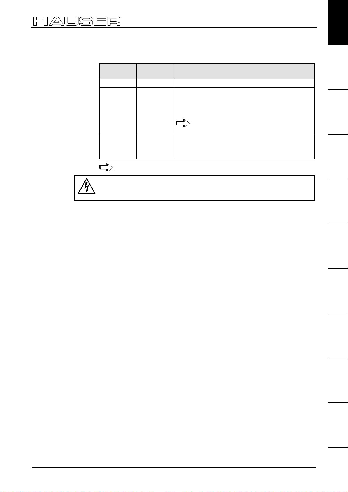
Meaning of LEDs on the front panel
COMPAX-M / -S
LED Color Meaning, when switched on
Ready green
Error red
24V DC present and initialization complete
COMPAX - Error (E1...E56) present or COMPAX is
initialized.
COMPAX-M / -S
Mains module
LED
red
Error
off on no errors
on off Heat sink temperature too high or
on on Ballast switching unit overload or
LED
green
Ready
Possible errors
error in logic voltage (24V DC too low or unit is defective)
Emergency stop is activated and ready contact is
released.
undervoltage (<100V DC or <80V AC).
COMPAX 1000SL
Status Red LED (H2) Green LED (H1)
24V not available off off
24V are switched on, boot up on off
Unit OFF off blinking
Unit error; drive switched off on blinking
Unit error; drive powered on on
Unit RUNNING off on
Caution!
If there is no control voltage, no displays will appear to indicate
that operating voltage is present.
10
Note:
With Error E40, external enabling is missing with COMPAX 45XXS, COMPAX
85XXS and COMPAX 1000SL (Hardware input).

Commissioning
After 24V DC of control voltage is switched on, COMPAX has two statuses
available once the initialization phase has been completed:
1. COMPAX is OFF
COMPAX is not configured (P149="0") or
with COMPAX XX70:
I12="0" (final stage blocked).
Now configure COMPAX (e.g. using the ServoManager / ParameterEditor).
Set P149="1"
Configuration is accepted with VC and VP of COMPAX.
2. COMPAX displays error E57
COMPAX is configured (P149="1"). However, operating voltage is not present.
Check COMPAX configuration
Alterations are accepted with VC and VP of COMPAX.
*)
Configuring
a) Using ServoManager:
P149="1", VP and VC are transferred when being downloaded to COMPAX
from the ServoManager.
b) Using hand-held terminal:
P149="1", VP and VC are generated by the hand-held terminal.
c) Without an auxiliary device, e.g. a terminal:
P149="1", VP and VC must be transmitted after COMPAX configuration.
Switch on operating voltage
With E57: acknowledge error by pressing Enter.
When OFF: command: "OUTPUT O0=0" or
switch 24V DC on / off
Motor is powered; COMPAX display shows "RUN".
Flow chart:
*
.
connection of control
initializing stage
COMPAX configured
(P149="1")
error E57
in COMPAX
display
check
configuration
VC, VP
connect
DC bus
voltage
clear
error E57
voltage 24 V DC
COMPAX not configured
configuration
24V DC
ON / OFF
RUN
motor enabled
(P149="0")
OFF in
Display
execute
P149="1",
VC, VP
connect
DC bus
voltage
OUTPUT
O0="0"
11

Switch-on status
5.3 Equipment replacement
COMPAX-M / -S
Previous software
!
Procedure for copying the complete COMPAX setting onto a new unit
!
Start ServoManager.
!
Connect old COMPAX via RS232.
!
Use menu "Insert: Axis: From controller" to set up an axis which contains all
≥≥≥≥
V2.0
COMPAX settings (all parameters: including system parameters, data records
and (with COMPAX XX70) existing curves).
!
Connect new COMPAX.
!
Use menu "Online: Download" to transfer data (without system parameters1) into
the new COMPAX.
Transferring system parameters
!
Call up ParameterEditor (Menu: PC Tools: ParameterEditor)
!
Use menu "Online: Copy" menu to transfer all parameters (including system
parameters) to COMPAX.
Previous software
Procedure for copying the complete COMPAX setting onto a new unit
!
Start ServoManager.
!
Connect old COMPAX via RS232.
!
Use menu "Insert: Axis: New" to set up a new axis.
!
Use menu "Online: Upload" to load all COMPAX settings (all parameters:
including system parameters, data records, and (in COMPAX XX70) existing
curves) into the new axis.
!
Connect new COMPAX.
!
Use menu "Online: Download" to transfer data (without system parameters) into
the new COMPAX.
≤≤≤≤
V2.0
Transferring system parameters
!
Call up ParameterEditor (Menu: PC Tools: ParameterEditor)
!
Use menu "Online: Copy" menu to transfer all parameters (including system
parameters) to COMPAX.
1
System parameters are internal parameters; you will only obtain an identical
COMPAX – setting if these are also transferred.
12
6. Conditions for usage
- for CE-compliant operation in industrial and
business sectors -
The EU guidelines on electromagnetic compatibility 89/336/EEC and electrical
means of production for use within particular voltage limits 73/23/EEC are satisfied,
if the following peripheral conditions are complied with.
Only operate the units in the condition in which they are supplied, i.e. with all
housing plates and the front cover.
COMPAX P1XXM, COMPAX 02XXM, COMPAX 05XXM and COMPAX 15XXM
may only be operated with HAUSER mains modules (NMD10 or NMD20) or on
COMPAX 35XXM.
Equipment replacement
Power filter:
Motor and
resolver cable:
Motors:
Control:
A power filter is required in the power line. The filtering can be executed
once for the entire system or as separate process for each unit.
The following power filters are required for standalone operation:
NMD10 / COMPAX 45XXS / COMPAX 85XXS: Order No.: NFI01/02
NMD20: Order No.: NFI01/03
COMPAX 35XXM: Order No.: NFI01/04 or /05
COMPAX 25XXS: Order No.: NFI01/01 or /06
COMPAX 10XXSL: Order No.: NFI01/01 or /02
Length of connection:
Only operate the unit with a HAUSER motor and resolver cable (with
connectors containing special surface screening).
In such cases, the following cable lengths are permitted.
Motor cable
Resolver cable < 100m
Operation with HAUSER motors.
Only operate with calibrated controller (avoid feedback oscillation).
connection between power filter and unit: unscreened: < 0.5m
screened: < 5m
< 100m (the cable must not be rolled up)
For motor lines of >20m, a motor output throttle must be used
Up to 16A nominal motor current: Type: MDR01/01 16A / 2mH.
Between 16A and 30A: Type: MDR01/02 30A / 1.1mH.
Over 30A nominal motor current: Type: MDR01/03 >30A /
0.64mH.
Earthing:
Cable laying:
Accessories
Warning:
!
The filter housing, the mains module and the COMPAX must be surface
connected with good metal conductivity and low inductivity to the cabinet ground.
!
Never secure the filter housing or the unit to coated surfaces.
!
Ensure that you have largest spacing possible between the signal and load lines.
!
Signal lines must never pass sources of strong interference (motors,
transformers, relays,...).
!
Only use accessories recommended by HAUSER (absolute value sensor,
encoder,...).
Provide large surface contact areas down both sides of all cable screening.
This is a product of the restricted sales class as per IEC 61800-3. In a domestic
environment, this product may cause high frequency disturbances, in which case
the user can be requested to implement suitable measures.
13

Start-up manual
COMPAX-M / -S
7. Start-up manual
Compact Servo Controller
14
7.1 Overview:
7.1.1 Components required
In addition to a COMPAX, you will require the following
components for a COMPAX application:
!
a motor with or without a transmission.
!
mains supply.
!
emergency stop circuit.
!
various cables for connecting components.
!
motor cable and resolver cable.
!
supply line for voltage supply.
!
supply line for 24V DC control voltage.
!
hand-held terminal or PC (with RS232 cable)
containing the ServoManager program for
configuring COMPAX.
7.1.2 Overview of unit technology
Overview:
Overview of unit technology
Unit
hardware
Common function
characteristics:
COMPAX P1XXM
COMPAX 02XXM
COMPAX 05XXM
COMPAX 15XXM
COMPAX-M and COMPAX-S
!!!!
work with the same firmware,
yet have differences with regard to
!
housing and assembly technology and
!
power areas.
The following table shows the main features of the range of available units
Interfaces: 16 (8 with COMPAX 1000SL) digital inputs/outputs,
RS232; machine zero, limit switch, override input
Fieldbus options: RS485, Interbus-S, Profibus, CS31, CAN – Bus,
CANopen, HEDA (synchronous serial realtime interfaces)
Other options (excluding COMPAX 1000SL): absolute encoder sensor; encoder
input; encoder simulation; D/A monitor
Supply via central mains module: NMD10 / NMD20: Up to max. 3*500V AC
Dimensions (DxHxW): COMPAX P1XXM:
340*400*60 [mm]
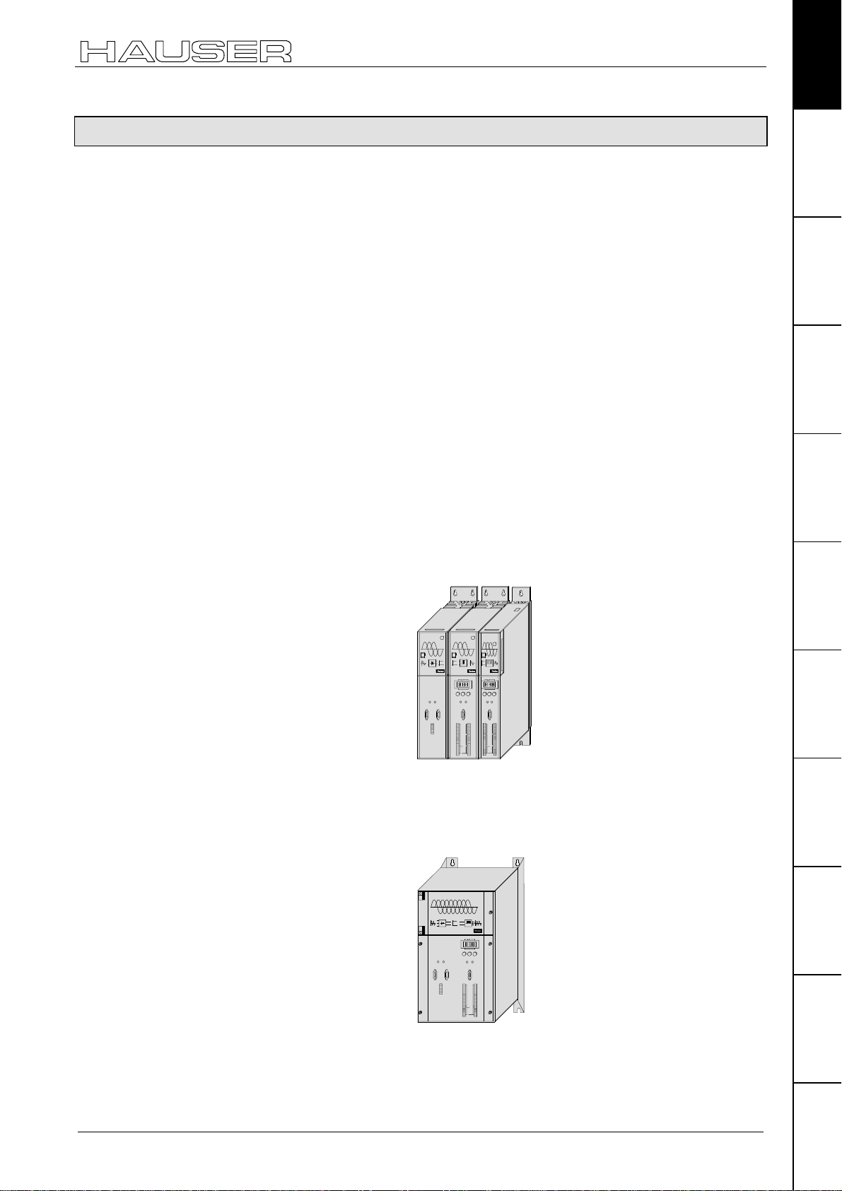
Design:
COMPAX-M with NMD
mains module
Installation: in series
Power Supply COMPAX-M
Ready Error
X6 X7
RS485IN OUT
X8
Control
Status Number
-+Enter
Ready E rror
X8 X10
X9 X11
COMPAX-M
DIGITAL
DIGITAL
Status
Number
Value
Value
-+Enter
Ready
Error
X6
X6
RS232
RS232
X8
X10
Input
Input
Output
Output
Test
Test
Control
Control
X9
X11
COMPAX-M:
340*400*85 [mm]
Power:
COMPAX ...
P1XXM: 3.8 kVA
02XXM: 4.5 kVA
05XXM: 8.0 kVA
15XXM: 17 kVA
Connector
assignment / cable
Technical dataConfigurationPositioning and
control functions
functions
Optimization
InterfacesAccessories /
COMPAX 35XXM
Supply Up to max. 3 * 500V AC (integrated power unit)
Dimensions
(DxHxW): 40 * 400 * 220 [mm]
Design:
COMPAX-M
Digital
Automation
StatusNumber
Value
-+Enter
Ready Error
Ready Error
X6 X7
X6
RS485IN OUT
RS232
X8
X8 X 10
Control
Input
Output
Test
Control
X9 X 11
options
Power
35.0 kVA
StatusParameterError list
15
Start-up manual
COMPAX-M / -S
COMPAX 1000SL
COMPAX 25XXS
COMPAX 45XXS
COMPAX 85XXS
Supply Up to max. 1*250V AC (integrated power unit)
Dimensions (DxHxW): 146*180*85 [mm]
Design:
Supply
Up to max. 1 (3)*250V AC (integrated power unit)
H2
H1
X15
X6X5X13
X17
Input
+-
24 V DC
RS232
Limit Switch
X7
X14
PE
HEDA Out HEDA In
Fieldbus In
Dump
Fieldbus Out
R
X12
X1 X4 X3
Encoder
Resolver
PE+ W
Motor Brake
UV
X19
X2
Input / Output
230 V AC
L1 N PE
COMPAX - SL
Dimensions (DxHxW): 220*240*130 [mm]
Design:
Status Number
COMPAX-S
Value
-+Enter
Ready Error
X6
RS232
X8 X1 0
Input
Output
Test
Control
Motion & Control
X9 X1 1
Supply Up to max. 3*500V AC (integrated power unit)
Dimensions (DxHxW): 275*350*125 [mm]
Power
1 kVA
Power
2.5 kVA
Design:
COMPAX-S
DIGITAL
Status Number
Value
Ready Error
RS232
Input
Output Output
Test Control
Power
4.5 kVA
8.6 kVA
ENTER+-
Input
X10X6X8
X11X9
16
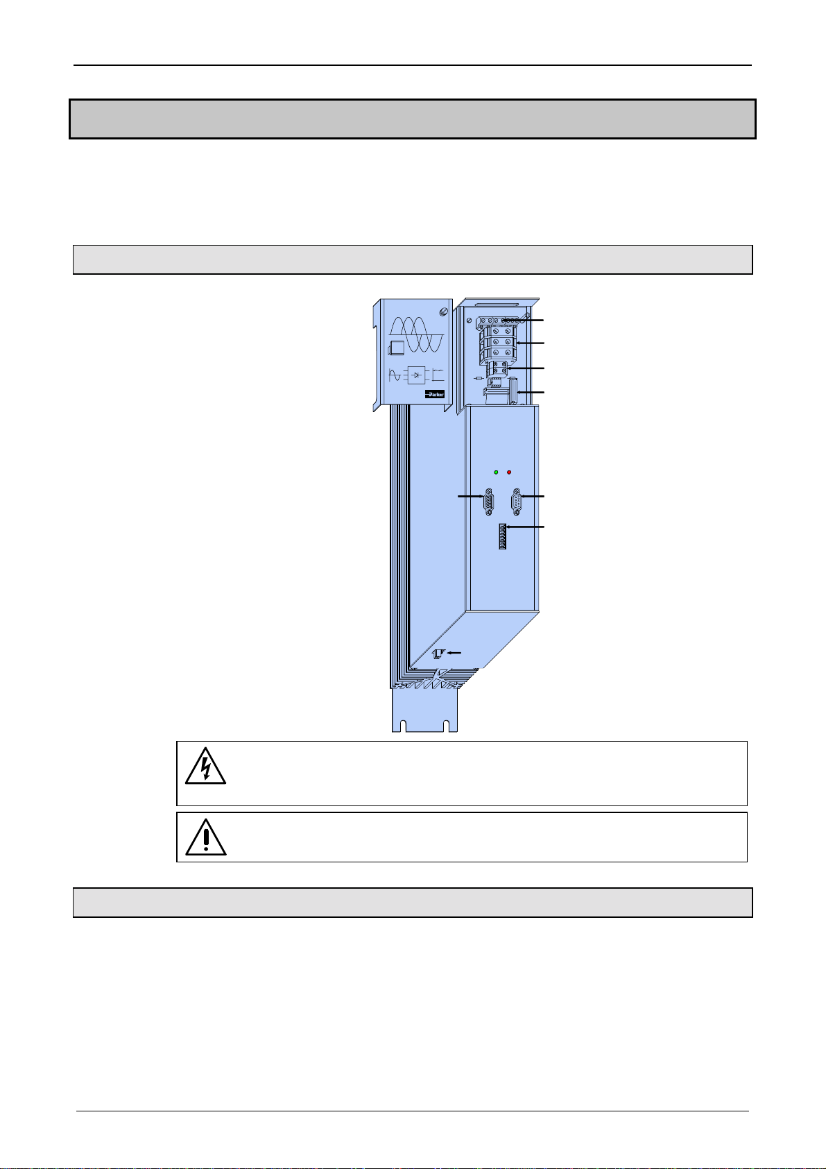
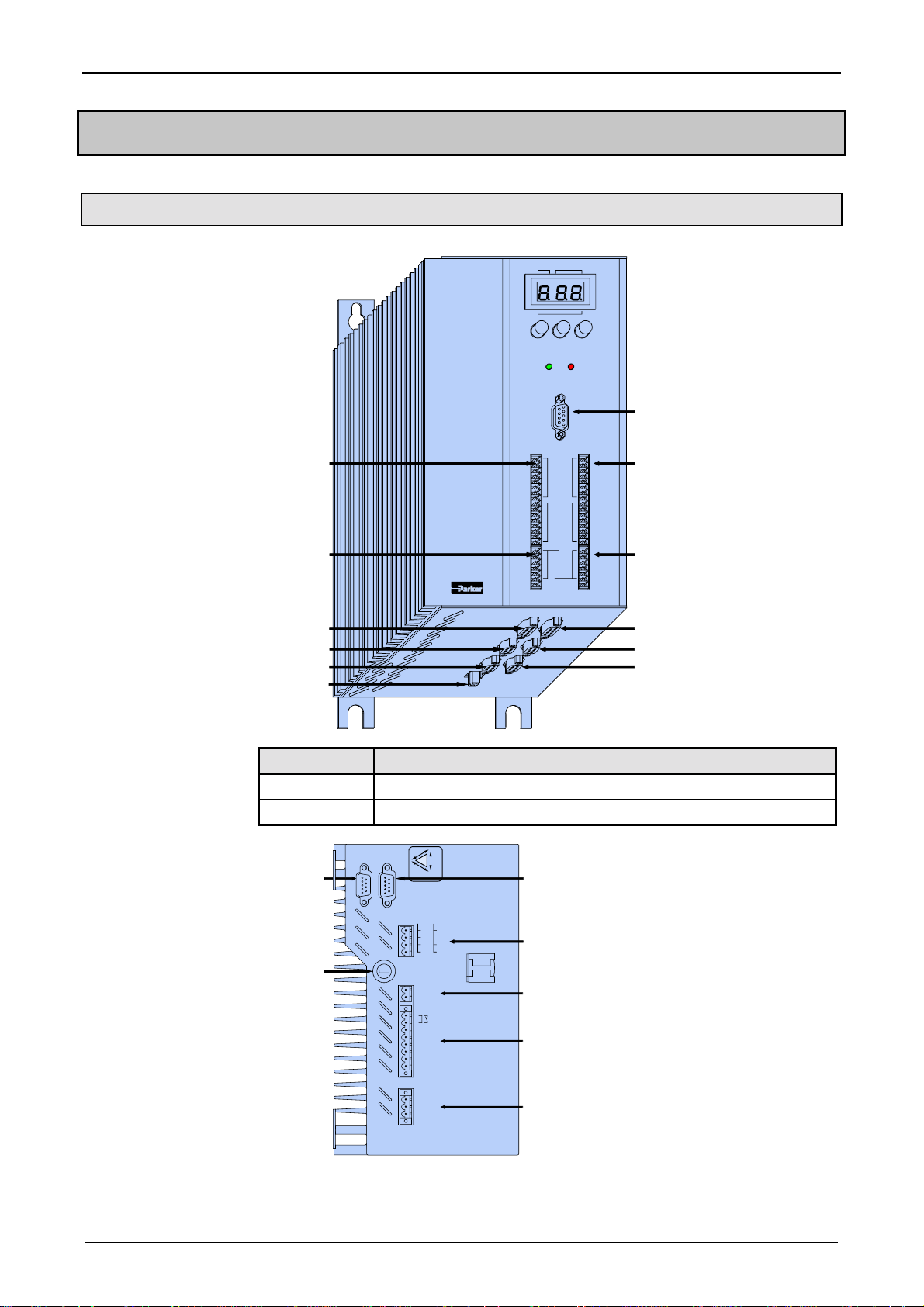
7.2 COMPAX-M unit features
COMPAX-M unit features
Connector and terminal assignment
Unit
hardware
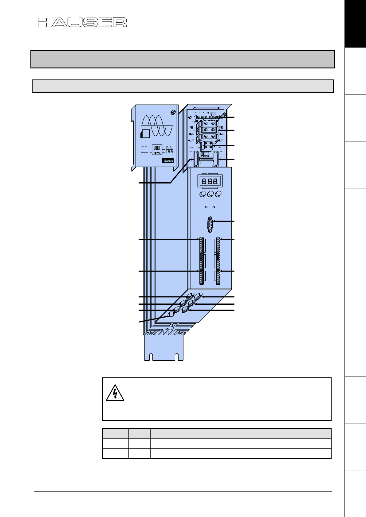
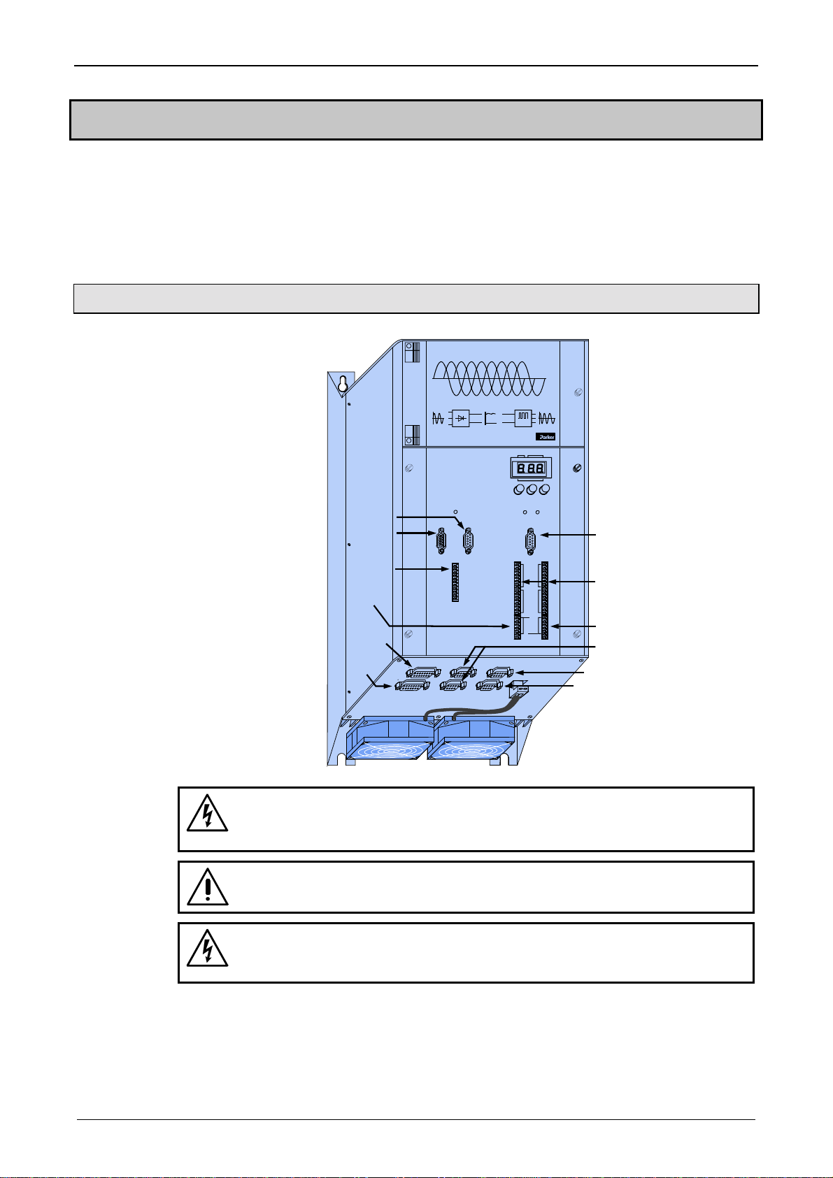
7.2.1 Connector and terminal assignment
COMPAX-M
X5 control- and
status- signal
bus-signals
input
X8 Input
/ Output
Number
Status
Value
+- Enter
Ready Error
X6
RS 232
X8 X10
Input
X1 motor
X2 intermediate loop
power connections
X3 24V control voltage
X4 control- and status
signals / bus signals
or short circuit plug
X6 RS232
X10 Input / Output
Connector
assignment / cable
Technical dataConfigurationPositioning and
control functions
Meaning of LEDs on
front plate
Output
X9 Test
X12 resolver
X14 HEDA
X16 absolute
encoder
X18 fan
Test
Control
X9 X11
X11 Control
X13 Encoder
X15 HEDA
X17 initiators
Before wiring up, always de-energize the unit.
Even once the mains supply has been switched off,
dangerous levels of voltage can remain in the system for
up to 5 min.
LED Color Meaning, when switched on
Ready green 24V DC present and initialization complete
Error red COMPAX - fault (I1...E56) present.
functions
Optimization
InterfacesAccessories /
options
StatusParameterError list
17
Start-up manual
COMPAX-M / -S
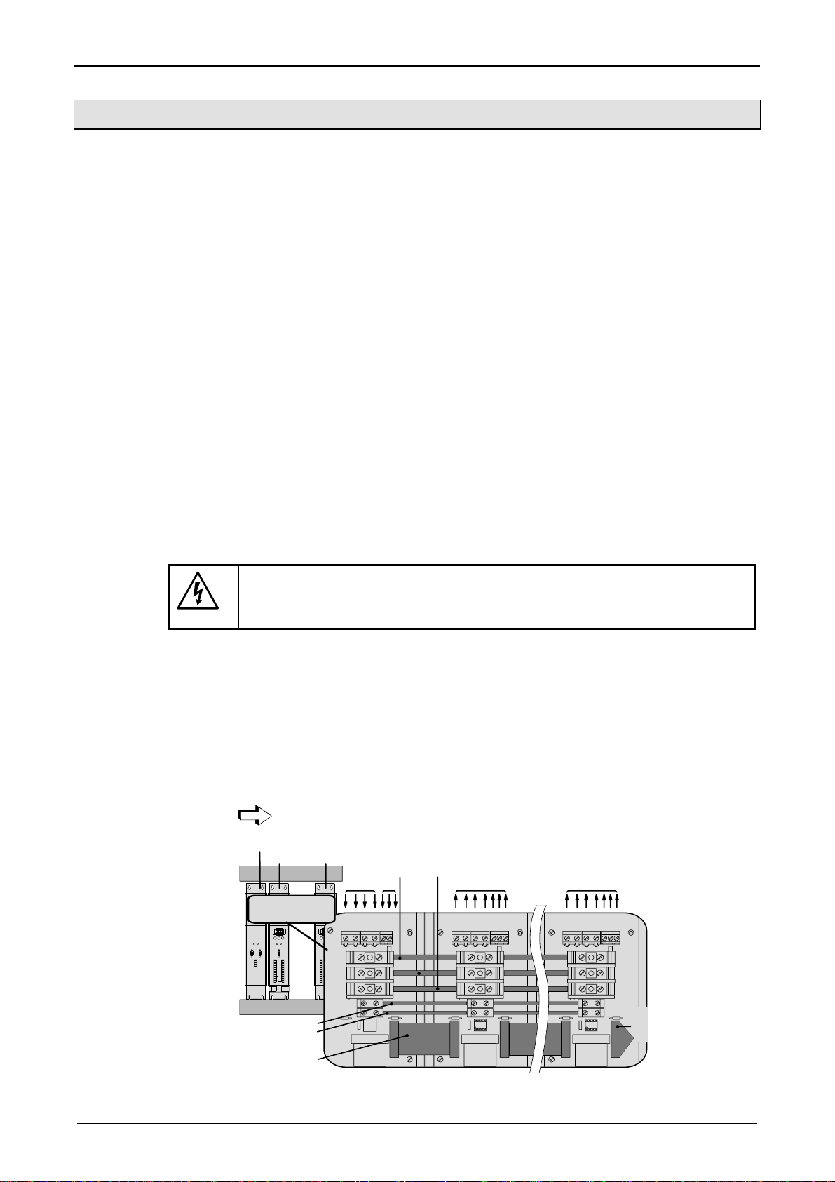
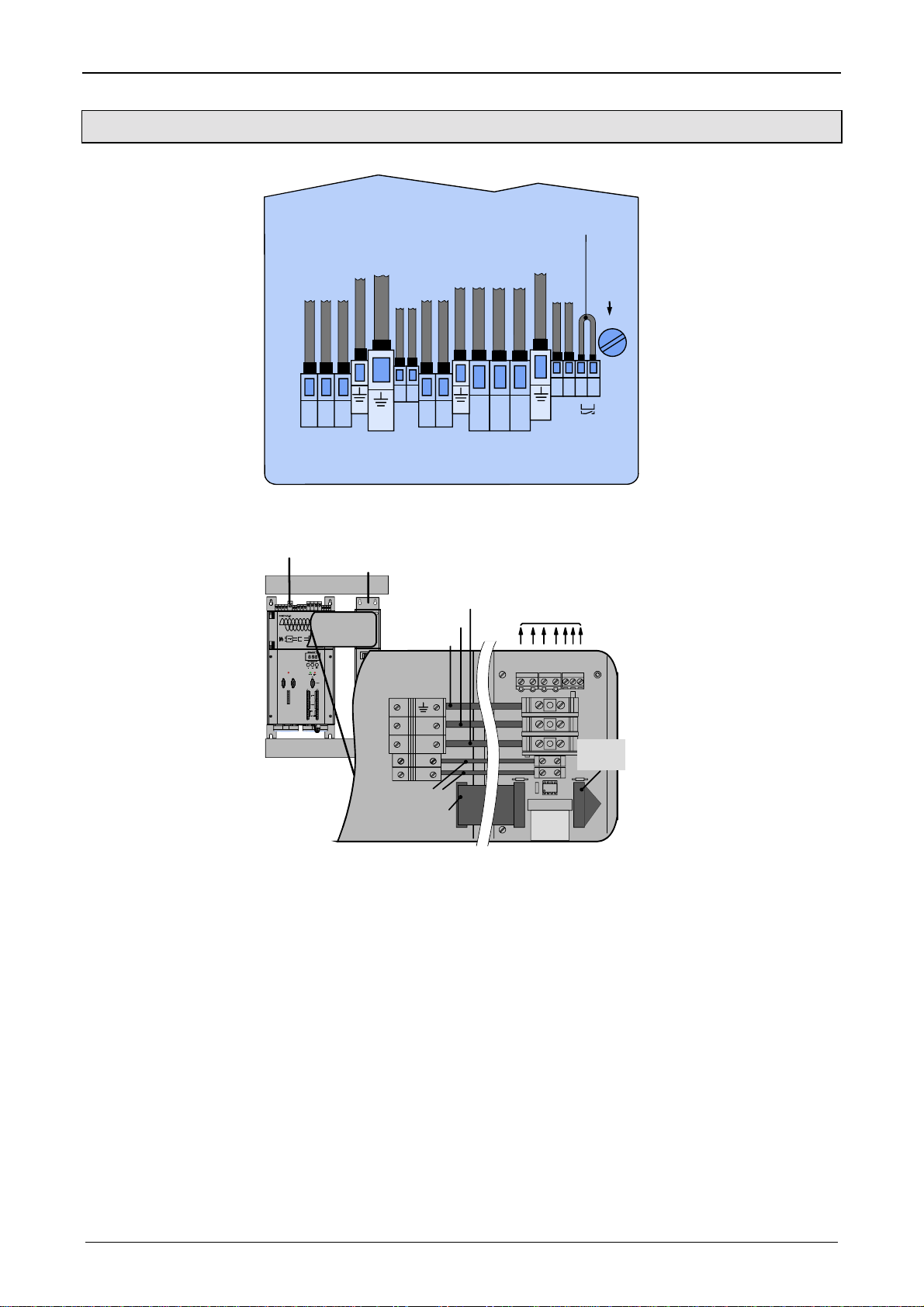
7.2.2 COMPAX-M system network, NMD10 / NMD20 mains module
A COMPAX-M drive system consists of one mains module and one or more drive
controllers. The units are coupled with one another with flatband cables (see
below). These are arranged behind the front plate cover of the power unit and the
drive controller.
The power unit converts mains power (up to 3 * 500V AC) into DC current for the
intermediate circuit.
The two connectors for connection to the bus systems are located on the front
plate of the power unit. The connection assignment complies with the specifications
for 2-cable remote bus.
The 24V DC control voltage required by the system network is supplied from the
power unit.
A connector terminal on the front of the power unit is used for connecting the
control and status signals (EMERGENCY STOP, readiness) which you can
incorporate in the control of the entire system.
These signals and the bus lines are connected internally via a preformed
doublesided flatband cable. These cables are included with the drive controller.
The connectors which receive these connection cables are housed under the front
plate cover of the mains module and the drive controller.
Short circuit
connectors
Wiring up the
system network
Attach a short circuit connector to the outgoing connector on the drive controller
that is furthest away from the mains module. The short circuit connector (order No.
102-908000) is included with the mains module.
Installation arrangement
Before wiring up, always de-energize the unit.
Even once the mains supply has been switched off, dangerous
levels of voltage can remain in the system for up to 5 min.
The wires required for creating the system network are included in the delivery.
Open the front cover (upper section of front side) by loosening the top right knurled
screw and wire up the following:
!
24V DC voltage supply.
!
PE and DC current.
!
Emergency stop, ready and bus signals with a terminating connector on the last
unit.
From the mains module to the individual COMPAX-M.
When delivered, the terminating connector is located on the mains module.
power supply module
COMPAX-M COMPAX-M
cable conduit
HAUSER
HAUSER
DIGITAL
POWER SUPPLY
COMPAX-M
Status
Number
Value
-
+Enter
Ready
Error
Ready Error
X6
X6 X7
...
RS232
RS485IN OUT
X10
X8
X8
Control
Input
Output
Test
Control
X9
X11
voltage supply
24V
emergency stop,
stand by and bus
signals
{
main 24V motor
HAUSER
DIGITAL
L1 L2L3 PE 24V
COMPAX-M
StatusNumber
Value
-+Enter
X1
Ready Error
X6
RS232
PE
X8 X10
Input
X2
Output
Test
+LS
Control
X9 X11
-LS
+
24V
X3
-
PE LS+ LS-
+-
X4
UVWPEbrake
X1
X2
X3
X5
PE+ -
motor
UVWPEbrake
PE+ -
X1
X2
X3
X4
X5
X4
last device
equiped
with
terminal
plug
18
COMPAX-M unit features
COMPAX-M system network, NMD10 / NMD20 mains module
Unit
hardware
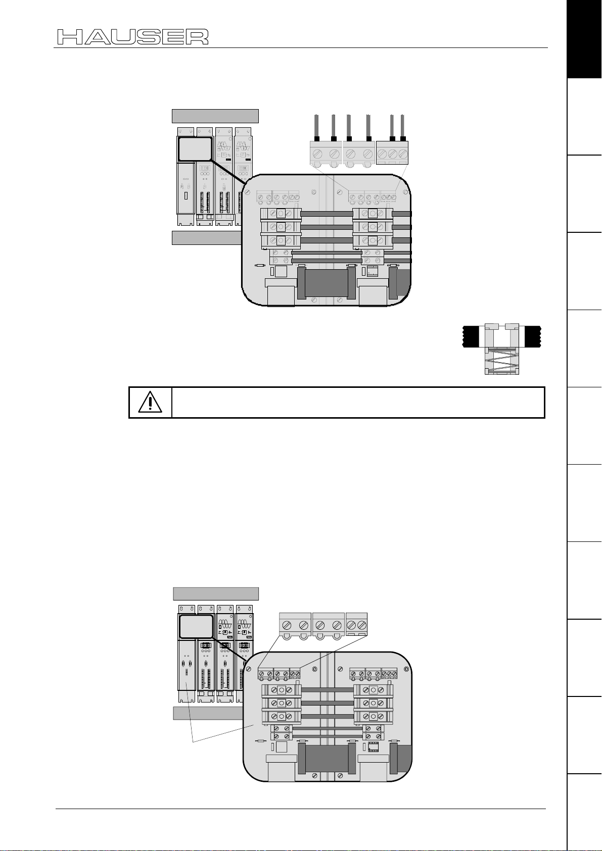
Wiring up the
motor
Screened
connection
Unit side
cable conduit
HAUSER
HAUSER
POWER SUPPLY
COMPAX- M
ReadyError
X6 X7
RS485INOUT
X8
Control
StatusNumber
-+Enter
X8 X10
X9 X11
UVWPE
black 1
black 2
COMPAX-M
COMPAX-M
DIGITAL
DIGITAL
DIGITAL
Motion & Control
Motion & Control
StatusNumber
Value
ReadyError
X6
RS232
Input
Output
Test
Control
StatusNumb er
Value
Value
-+Enter
-+Enter
ReadyError
ReadyError
X6
X6
RS232
X8 X10
Input
Output
Test
Control
X9 X11
L1L2L3PE 24V
RS232
X8 X10
Input
X1
Output
Test
Control
PE
X9 X11
123 45
X1
+-
X2
+LS
-LS
+
24V
X3
-
black 3
UVWPEbrake
X1
X2
X5
brake
-
+
PE
free
green/
yellow
black 4
black 5
PE + -
X3
X4X4
Note the screened connection of the motor cable on the
upper unit side.
Clamp the motor cable with the open place of the screen
braid under the ground terminal (see figure on the right).
Connector
assignment / cable
Technical dataConfigurationPositioning and
control functions
Wiring up mains
power / control
voltage
Only wire up brake in motors which have a holding brake! If not, do not
wire.
The mains supply and the control voltage supply are provided by the mains
module.
Power supply:
!
3*80V AC – max. 3*500V AC; 45 - 65Hz
!
Fuse protection:
NMD10: 16A (K circuit breaker in 20A)
Control voltage
!
24V DC ±10%
Ripple <1V
Fuse protection: max. 16A
SS
NMD20: 35A
K circuit breaker or similar Neozed
fusible cut-out.
cable conduit
HAUSER
HAUSER
POWER SUPPLY
COMPAX-M
Ready Error
X6 X7
RS485IN OUT
X8
Control
StatusNumber
-+Enter
Ready Error
X8 X10
X9 X11
L1 L2L3 PE
1
COMPAX-M
COMPAX-M
DIGITAL
DIGITAL
Motion & Control
StatusNumber
Value
Value
-+Enter
Ready Error
X6
X6
RS232
RS232
X8 X10
Input
Input
Output
Output
Test
Test
Control
Control
X9 X11
DIGITAL
Motion & Control
StatusNumber
Value
-+Enter
Ready Error
X6
L1 L2L3 PE 24V
RS232
X8 X10
Input
X1
Output
Test
Control
X9 X11
PE
X1
X2
+LS
-LS
+
X3
24V
-
23 45
+-
24V
-
+
UVWPEbrake
X1
X2
X3
PE+ -
power supply
module
X5
X4X4
functions
Optimization
InterfacesAccessories /
options
StatusParameterError list
19
Start-up manual
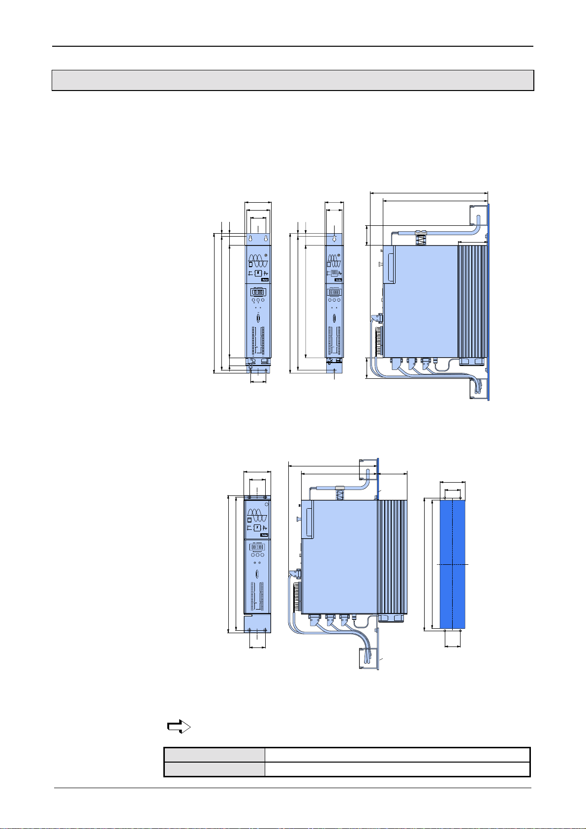
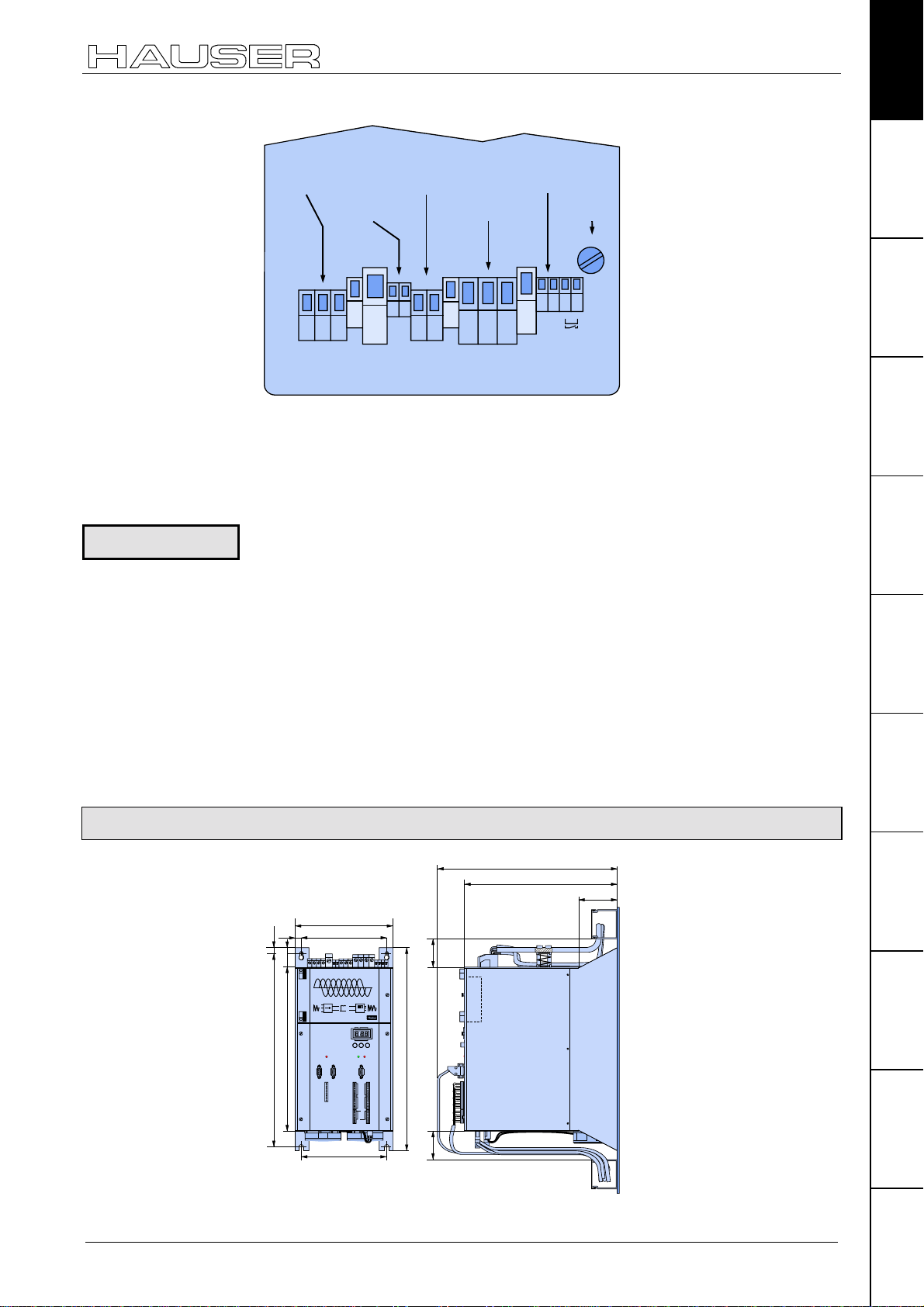
7.2.3 COMPAX-M dimensions/installation
The specific design of the COMPAX-M controller allows for wall installation
(distance: 61mm in COMPAX P1XXM and 86mm in larger units) in two different
ways.
COMPAX-M / -S
Direct
wall installation:
Indirect
wall installation:
Direct wall installation and dimensions of COMPAX-M and the mains
modules.
02XXM, 05XXM,
15XXM, NMD10
10
40
450
430
364
31
Attach with four 6-mm
hex-socket-head-screws
& NMD20
85
75
50
COMPAX-M
DIGITAL
Status Number
Value
Enter
Ready Error
RS232
X8 X10
Input
Output
Test
Control
50
450
P1XXM
60
49
10
40
COMPAX-M
DIGITAL
StatusNumber
Value
430
-+Enter
364
Ready Error
X6
RS232
X10
X8
Input
Output
Test
Control
X9
X11
Attach with two 6-mm
hex-socket-head-screws
390
340
65
96
65
The controllers are attached to the mounting plate with the back of the heat sink.
Indirect wall installation of COMPAX 02XXM, COMPAX 05XXM and COMPAX
15XXM and the mains modules NMD10 and NMD20.
294
244 96
mounting
plate
82
50
COMPAX-M
85
50
Fan configuration
20
DIGITAL
Status Number
Value
-+Enter
Ready Error
424
X8 X10
Output
Test
X9 X11
X6
RS232
Input
Control
441,5
50
mounting
plate
424
408
50
The heat sink is pushed back through a hole in the panel (on right of diagram). A
separate heat chamber is created between the installation plate and the rear wall
of the control cabinet. The angles required under designation MTS2 must be
complied with.
Indirect wall installation is not possible with COMPAX P1XXM.
Units with fan:
COMPAX P1XXM, COMPAX 05XXM, COMPAX 15XXM
Units without fan: COMPAX 02XXM, NMD10, NMD20
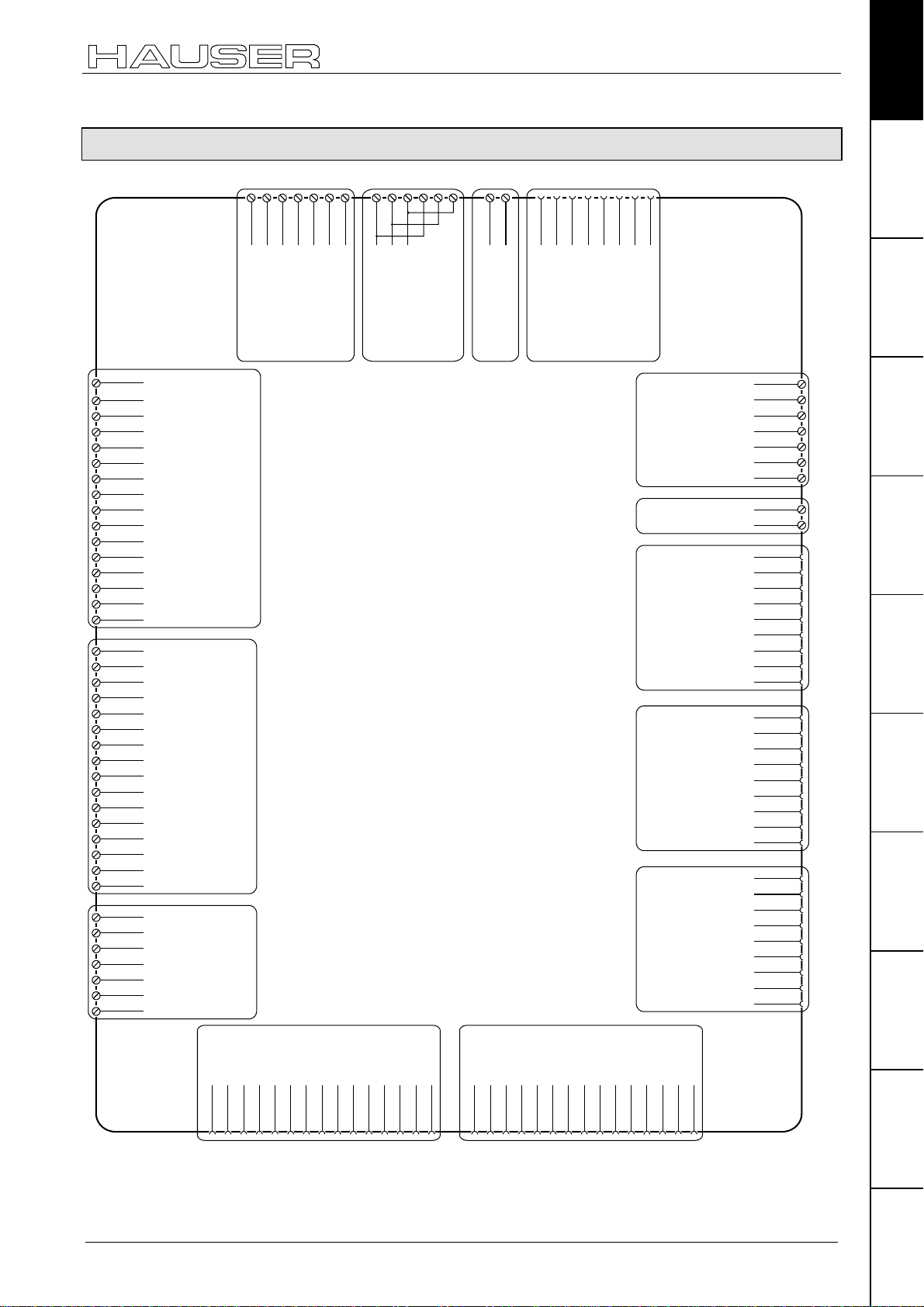
7.2.4 Connector assignment COMPAX-M
X1/2
X1/1UX1/3
V
X1/4
X1/5
W
PE
PE
Br-
Br+
PE
+LS
-LS
X3/1
X3/20VX6/2
+24 V
COMPAX-M unit features
Connector assignment COMPAX-M
X6/3
X6/4
X6/5
X6/6
X6/7
X6/8
X6/9
RxD
TxD
DTR
GND
DSR
RTS
CTS
+5V
Unit
hardware
Connector
assignment / cable
X8/1
I1
X8/2
I2
X8/3
I3
X8/4
I4
X8/5
I5
X8/6
I6
X8/7
I7
X8/8
I8
X8/9
O1
X8/10
O2
X8/11
O3
X8/12
O4
X8/13
O5
X8/14
O6
X8/15
O7
X8/16
O8
X10/1
I9
X10/2
I10
X10/3
I11
X10/4
I12
X10/5
I13
X10/6
I14
X10/7
I15
X10/8
I16
X10/9
O9
X10/10
O10
X10/11
O11
X10/12
O12
X10/13
O13
X10/14
O14
X10/15
O15
X10/16
O16
X9/1
+24V
X9/2
GND
X9/3
reserviert
X9/4
reserviert
X9/5
24V*
15V - 24V emergency
X9/6
stop*
X9/7
housing
* can be
parameterized
X8:
input /
output
I1...I8
O1...O8
X10:
input /
output
I9...I16
O9...O16
X9
housing
+8V
REF-
X1:
motor
brake
SIN-
GND
ST+
+5 V
TEMP
X2:
power intermediate loop
COS-
COS+
SIN+
REF+
X3:
control
voltage
ST-
housing
X6:
RS232
Technical dataConfigurationPositioning and
X11/1
+24V
X11/2
GND
shield
24V
0V
shield
+24V
GND
Sig.MN
Sig. E2
Sig. E1
NC
RxC
TxC
RxD
TxD
RxC/
TxC/
RxD/
TxD/
NC
NC
GND
NC
D+
+24V
T-
D-
T+
X11/3
X11/4
X11/5
X11/6
X11/7
X18/+
X18/-
X17/1
X17/2
X17/3
X17/4
X17/5
X17/6
X17/7
X17/8
X17/9
X14(15)/1
X14(15)/2
X14(15)/3
X14(15)/4
X14(15)/5
X14(15)/6
X14(15)/7
X14(15)/8
X14(15)/9
X16/1
X16/2
X16/3
X16/4
X16/5
X16/6
X16/7
X16/8
X16/9
control functions
functions
Optimization
InterfacesAccessories /
options
StatusParameterError list
Override
DA-channel 2
X11
DA-channel 3
Override (old)
X18: fan
(option D1)
X17:
DA-channel 0
DA-channel 1
GND 24V
DA-monitor
initiators
X14/X15:
HEDA
X16:
Absolut
encoder
X13: encoderX12: resolver / SinCos
+5V
N2/
B2/
A2/
N1/
B1/
A1/
GND
X12/1
X12/2
X12/3NCX12/4
X12/5
X12/6NCX12/7
X12/8
X12/9
X12/10
X12/11
X12/12
X12/13
X12/14
X12/15
X13/1
X13/2N2X13/3B2X13/4A2X13/5N1X13/6B1X13/7A1X13/8
X13/9
X13/10
X13/11
X13/12
X13/13
X13/14
X13/15
The assignment of X12 does not apply for the S3 option.
The bus connections are made via the mains module.
21
Start-up manual
7.3 Mains module NMD10/NMD20
The mains module ensures the supply of current to the COMPAX-M (not COMPAX
35XXM) axis controller and the SV drive connected into the network. It is
connected to the 3-phase power supply with 3 * 400V AC and PE. 24V DC voltage
must be provided for the control electronics.
7.3.1 Overview NMD
COMPAX-M / -S
Power Supply
X6 bussystems IN
L1 L2 L3 PE 24V
X1
PE
X2
+LS
-LS
+
24V
X3
-
IN OUTRS 485
X18 fan
X6
Ready Error
voltage supply
PE + -
X8
3*(80-500)V AC/
X1 24V CC
PE
X2 power inter-
+LS
mediate loop
-LS
X3 control
+
24V
-
voltage 24 V
X4
X4 control- and
status-signals
Bus signals
continuation
X7
Control
X7 bus-systems
OUT
X8 Control
Before wiring up, always de-energize the unit.
Even once the mains supply has been switched off, dangerous
levels of voltage can remain in the system for up to 5 min.
The PE connection must be a 10mm
7.3.2 Dimensions / installation
Dimensions and installation of the NMD10 and NMD20 power units correspond to
the data for COMPAX-M (see Page 20).
22
2
version

7.3.3 NMD connector assignment
Mains module NMD10/NMD20
NMD connector assignment
Unit
hardware
X1/1
X1/1
L1
L1
X1/2
X1/2
L2
L2
X1/3
X1/3
X1/4
X1/4
X1/5
X1/5
X1/6
X1/6
X6: input bus systems X7: output bus systems
Assignment depends on the
bus system
X1:
L3
L3
voltage
supply
PE
PE
+24V
+24V
0V
0V
PF
PE
X2:
power inter-
+LS
+LS
mediate loop
-LS
-LS
X8
15V-24 V emerg. stop
Assignment depends on the
bus system
X3:
Control
voltage
7.3.4 Technical data / power features NMD
Function
Generates DC current when run directly off a mains source.
CE conformity
!
EMC immunity/emissions as per EN61800-3.
!
Safety: VDE 0160/EN 50178.
stand by
housing
+24V
GND
+24V
+24V
0V
X8/1
X8/2
X8/3
P
X8/4
S
X8/5
X8/6
X8/6
Connector
assignment / cable
Technical dataConfigurationPositioning and
control functions
Output power
Nominal power Peak power
NMD10: 10 kW 20 kW (<3s)
NMD20: 20 kW 40 kW (<3s)
Mains fuse protection
NMD10: 16A (K circuit breaker in 20A)
NMD20: 35A
K circuit breaker or similar Neozed fusible cut-out.
Supply voltage up to max. 3*500V AC
!
Operating range: 3*80V AC - 3*500V AC, 45 - 65 Hz.
Typical AC mains: 400V ±10%; 460V ±10%; 480V ±5%
!
Layout of contactors for the power supply:
Capacity according to device performance: Application group AC3.
Control voltage
!
21.6V up to 26.4V DC (0.8A)
!
Ripple: < 1V
!
Fuse protection: max. 16A
SS
Dissipation power
!
without fan: max. 120W (standard)
!
with fan: max. 250W.
functions
Optimization
InterfacesAccessories /
options
StatusParameterError list
23
Start-up manual
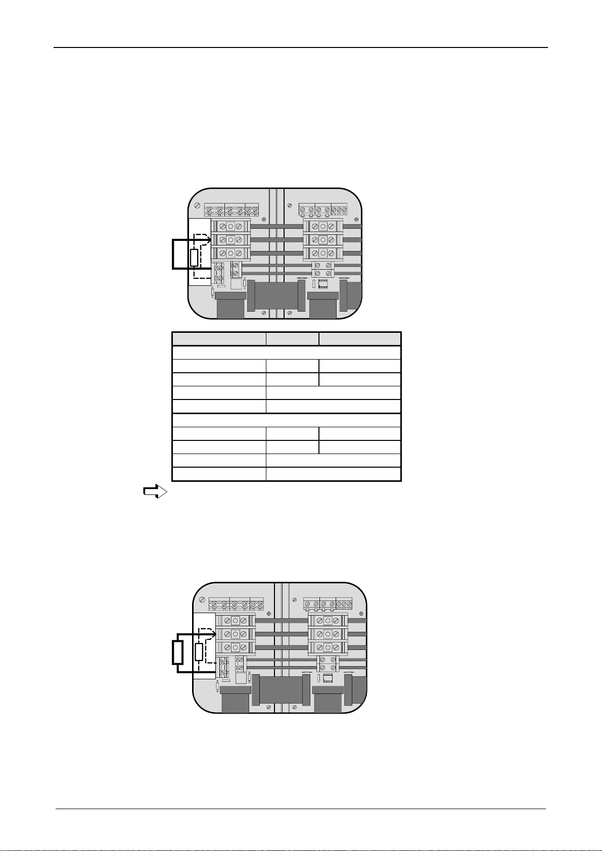
Overvoltage limitation
Energy recuperated during braking is stored in the supply capacitors. The capacity
and storable energy is:
NMD10/NMD20: 1100µµµµF / 173 Ws
If the energy recuperated from braking causes overvoltage, then ballast
resistances are engaged.
COMPAX-M / -S
Activation of the
internal ballast
resistance for
NMD20
Maximum braking
power:
The internal ballast resistance is activated by a bridge between +LS and X5/1.
In the NMD20 delivery status this bridge is fitted.
UVWPEBrake
X1
X2
X3
X5
PE+ -
X4X4
X3
24V
+-
L1 L2 L3 PE
X1
X2
PE
+LS
-LS
ext
int
RB
RB
1
X5
2
Braking power Duration Cooling down time
NMD10
17 kW <50 ms
4.0 kW <1s
≥
≥
10s
50s
Without fan: 120W unlimited
With fan: 250W unlimited
NMD20
9.5 kW <50 ms
2.5 kW <1s
≥
≥
10s
50s
Without fan: 120W unlimited
With fan: 200W unlimited
Connecting the
external ballast
resistance
External ballast resistances can be used with NMD20 (see Page 193).
If the braking power of the internal ballast resistance is insufficient, an external
ballast resistance can be connected.
The external ballast resistance is connected between +LS and X5/2.
To do this, the bridge between +LS and X5/1 must be removed.
The full braking power cannot be used with this bridge present.
UVWPEBrake
X1
X2
X3
X5
PE+ -
X4X4
RB
L1 L2 L3 PE
X1
X2
PE
+LS
-LS
ext
ext
int
RB
RB
1
X5
2
24V
+-
X3
Output X5 is protected from short circuits.
Thermal protection
An emergency stop is triggered at 85°C heat sink temperature, the ready contact is
released and the red LED lights up.
24
Mains module NMD10/NMD20
Technical data / power features NMD
If a phase malfunctions, no displays appear
Unit
hardware
Error diagnosis in
the mains module
LED red
Error
off on
on off
LED green
Ready
Possible errors
no errors
!
Heat sink temperature too high
or
!
error in logic voltage (24V DC too low or unit is
defective)
Emergency stop is activated and ready
contact is released.
on on
!
Ballast switch overloaded
or
!
undervoltage (<100V DC or <80V AC).
Ready contact and green LED are coupled.
Caution!
If the unit has no control voltage, no displays will indicate that operating voltage is
present.
Connector
assignment / cable
Technical dataConfigurationPositioning and
control functions
functions
Optimization
InterfacesAccessories /
options
StatusParameterError list
25
Start-up manual
7.4 COMPAX 35XXS unit features
The 35 kW servo control COMPAX 35XXM - a performance upgrade to the
COMPAX family.
!
Compact unit with output currents of 50
unit.
!
Additional COMPAX-M controllers of up to 15 KW can be arranged in rows.
7.4.1 Plug and connection assignment COMPAX 35XXM
COMPAX-M
Aeff
/ 100
Digital
Number
Status
Aeff
COMPAX-M / -S
(<5s) with integrated power
Bus
systems:
X7 OUT
X5 IN
X19
Control
X9 Test
X13
Encoder
X12
Resolver
H1
X5 X7
IN OUT
X19
Control
Value
+-
Ready
Error
X6
X8 X10
Input
Output
Test
Control
X9 X11
Enter
RS 232
X6 RS232
X8/X10 In-/
Output
X11 Control
X14/X15
HEDA
X17 Initiators
X16 Absolute
encoder
Before wiring up, always de-energize the unit.
Even once the mains supply has been switched off, dangerous
levels of voltage can remain in the system for up to 5 min.
When working with motors without a holding brake, the brake lines
must not be connected to COMPAX
26
Caution!
If the unit has no control voltage, no displays will indicate that operating
voltage is present.
Plan view
AC - voltage
up to 500V AC
L1 L2 L3
Mains Input
X 20
24V control
voltage
PE
PE
+
DC - In
24 V
X 21
external
ballast
resistor
-
Resistance
PE
Braking
X 22 X 1
COMPAX 35XXS unit features
Installation and dimensions of COMPAX 35XXM
motor
brake
Motor
Brake
X 23
F1
3.16A
F1
-
motor
U
VW
Motor
+
PE
Unit
hardware
Connector
assignment / cable
Technical dataConfigurationPositioning and
Specific technical
data
Supply voltage up to max. 3 * 500V AC
Operating range: 3*80V AC - 3*500V AC; 45 - 65 Hz.
Typical AC mains: 400V ±10%; 460V ±10%;480V ±5%
!
Layout of contactors for the power supply:
Capacity according to device performance: Application group AC3
Note!
Switching on the operating voltage for a second time:
Before switching on the operating voltage for a second time, you must wait for at
least 2.5 minutes otherwise you may overload the condenser load resistance.
Control voltage
!
21.6V to 26.4V DC • Ripple: < 1VSS • fuse protection: max. 16A
Mains supply fuse protection
62A K circuit breaker or suitable Neozed conventional fuse.
Regeneration mode
!
Storable energy: 3450µF/542 Ws
!
External ballast resistance: 10Ω/2 kW
For the external ballast resistors available, please see Page 193.
7.4.2 Installation and dimensions of COMPAX 35XXM
390
340
86
14
10
38
218
190
COMPAX-M
control functions
functions
Optimization
InterfacesAccessories /
options
Digital
Number
Status
Value
430
363
IN OUT
X5 X7
+-Enter
H1
Ready Error
X19
X8 X10
Control
Output
Test
X9 X11
190
450
X6
RS 232
Input
Control
65 65
Fastening with 4 M6 hex-socket head screws.
StatusParameterError list
27
Start-up manual
7.4.3 Wiring COMPAX 35XXM
Wiring up motor,
mains power /
control voltage
and external
ballast resistance
500V AC
Supply up to
L1 L2 L3
PE
green / yellow
COMPAX-M / -S
Connection for
external contact
for brake control
Motor
U
VW
PE
green / yellow
black 3
black 2
black 1
Motor
black 5
black 4
F1
3.16A
brake*
F1
+
24V Control voltage
-
External
braking resistance
PE
green / yellow
Wiring up system
network
W
11121314
+
PE
Motor
Brake
-
X 23
123
L1 L2 L3
Mains Input
X 20
45
68910
7
-
+
PE
DC - In
24 V
X 21
PE
Braking
Resistance
X 22 X 1
UV
Motor
* max. 1.6A
The PE connection must be a version of at least 10mm
COMPAX 35XXM
X5 X7
IN OUT
COMPAX-M / SV-M
Cable conduit
H1
X19
Control
...
...
HAUSER
DIGITAL
COMPAX-M
Status Number
Value
-+Enter
Ready Error
X6
RS232
X8 X10
Input
Output
Test
Control
X9 X11
+
24V
-
Voltage supply 24V
Emergency stop,
stand by and
bus signals
LS-
LS+
Motor
PE
UVWPEBrake
PE+ -
X1
18
17
16
15
X2
Last device
equiped with
X3
X5
terminal plug
X4
2
28
7.4.4 COMPAX 35XXM connector assignment
X21/1
X21:
Control
voltage
PE
+LS
-LS
+24V
0V
+24V
GND
+24V
24V
+24V
Enable
Shield
RxD
TxD
DTR
GND
DSR
RTS
CTS
+5V
X21/2
+24 V
X19/1
X19/2
X19/3
X19/4
X19/5
X19/6
X19/7
X19/8
X19/9
X19/10
X19/11
X6/2
X6/3
X6/4
X6/5
X6/6
X6/7
X6/8
X6/9
0V
X3/1
X3/2
X3/2
PE
Braking
resistance
X22: Braking
resistance
Enable final stage
X12/1
X12/2
X12/3
X12/4
X12/5
X12/6
X12/7
X12/8
X12/9
X12/10
X12/11
X12/12
X12/13
X12/14
X12/15
X13/1
X13/2
X13/3
X13/4
X13/5
X13/6
X13/7
X13/8
X13/9
X13/10
X13/11
X13/12
X13/13
X13/14
X13/15
X8/1
X8/2
X8/3
X8/4
X8/5
X8/6
X8/7
X8/8
X8/9
X8/10
X8/11
X8/12
X8/13
X8/14
X8/15
X8/16
X10/1
X10/2
X10/3
X10/4
X10/5
X10/6
X10/7
X10/8
X10/9
X10/10
X10/11
X10/12
X10/13
X10/14
X10/15
X10/16
X9/1
X9/2
X9/3
X9/4
X9/5
X9/6
X9/7
X20/2
X20/1L1X20/3
X20:
AC Supply
I1
I2
I3
I4
I5
I6
I7
I8
O1
O2
O3
O4
O5
O6
O7
O8
I9
I10
I11
I12
I13
I14
I15
I16
O9
O10
O11
O12
O13
O14
O15
O16
+24V
GND
reserved
reserved
24V
15-24V Emerg. stop*
Housing
X8:
Input / output
I1...I8; O1...O8
X10:
Input / output
I9...I16; O9...O16
X9
* can be parameterized
L2
L3
PE
PE
HV dc and 24V
for additional
COMPAX-M
X7: output bus systems
Assignment depends on
the bus system
output bus systems
X5:
Assignment depends on
the bus system
Stand by P
Stand by S
15-24V Emerg.stop
reserved
X19
X6:
RS232
COMPAX 35XXS unit features
COMPAX 35XXM connector assignment
X1/2
X1/1UX1/3
V
X1:
Motor
Housing
+8V
NC
REFSINNC
GND
ST+
+5 V
TEMP
COSCOS+
SIN+
REF+
ST-
Housing
N2
B2
A2
N1
B1
A1
+5V
N2/
B2/
A2/
N1/
B1/
A1/
GND
W
PE
X12: Resolver / SinCos
X13: Encoder
X23/3
X23/1
X23/2
Br-
Br'+
Br'+
X23:
Motor brake
X23/4
Br+
Override
DA-channel 2
X11
DA-channel 3
Override (old)
Shield
X18:
Fan
DA-channel 0
DA-channel 1
Shield
(Option D1)
GND 24V
Sig.MN
Sig. E2
X17: DA-monitor
initiators
Sig. E1
X14/X15:
HEDA
X16:
Absolute
encoder
+24V
GND
24V
0V
+24V
GND
NC
RxC
TxC
RxD
TxD
RxC/
TxC/
RxD/
TxD/
NC
NC
GND
T+
NC
D+
+24V
X14(15)/1
X14(15)/2
X14(15)/3
X14(15)/4
X14(15)/5
X14(15)/6
X14(15)/7
X14(15)/8
X14(15)/9
T-
D-
X11/1
X11/2
X11/3
X11/4
X11/5
X11/6
X11/7
X18/+
X18/-
X17/1
X17/2
X17/3
X17/4
X17/5
X17/6
X17/7
X17/8
X17/9
X16/1
X16/2
X16/3
X16/4
X16/5
X16/6
X16/7
X16/8
X16/9
Unit
hardware
Connector
assignment / cable
Technical dataConfigurationPositioning and
control functions
functions
Optimization
InterfacesAccessories /
options
StatusParameterError list
The assignment of X12 does not apply for the S3 option.
29
Start-up manual
COMPAX-M / -S
7.5 COMPAX 25XXS unit characteristics
7.5.1 COMPAX 25XXS connector and connection assignment
Statu s
Number
Meaning of the
LEDs on the front
plate
COMPAX-S
X8 input
/ output
X9 test
X12 resolver
X14 HEDA
X16 absolute
Value
+-Enter
Ready
Error
X6
RS 232
X8
X9
X10
Input
Outp ut
Test
Control
X11
X6 RS232
X10 digital input
and output
X11 control
X13 encoder
X15 HEDA
X17 initiators
X18 fan
LED / color Meaning, when switched on
Ready / green 24V DC present and initialization complete
Error / red
COMPAX - fault (E1...E56) present.
Plan view of
COMPAX 25XXS
30
X5 Bus
systems IN
F19
3.16 AT
L3
C
A
V
0
3
2
L1
C
A
230V AC
V
0
3
2
L2
line to line voltage
!
max. 230V AC +10%
3 x 230V AC
X2/
X3/
X1/
X4/
1 x 230V AC
PE
PE
4
3
L3
L2
2
1
2
1
8
7
6
5
4
3
2
1
3
2
1
N
L1
L
-
+
-
+
PE
W
V
U
PE
BB-
+
Bus systems
X7
X2
supply
24V DC
X3
supply
motor and
X1
motor brake
braking
X4
resistance
OUT
AC

COMPAX 25XXS unit characteristics
COMPAX 25XXS connector and connection assignment
Before wiring up, always de-energize the unit.
Even once the mains supply has been switched off, dangerous
levels of voltage can remain in the system for up to 5 min.
When working with motors without a holding brake, the brake lines
must not be connected to COMPAX
Unit
hardware
Connector
assignment / cable
Wiring up motor
The PE connection occurs with 10mm2 under a fixing bolt
Caution!
If the unit has no control voltage, no displays will indicate that operating
voltage is present.
On unit side
X5 RS485 IN
RS485
X7
OUT
AC
X2
supply
F19 3.16 AT
24V DC
X3
supply
motor and
X1
motor brake
braking
X4
resistance
L3
C
A
V
0
3
2
L1
C
A
230V AC
V
0
3
2
L2
line to line voltage
!
max. 230V AC +10%
3 x 230V AC
1 x 230V AC
PE
PE
L3
L2
N
L1
L
+
+
PE
W
V
U
PE
BB-
+
sheetshielding of motor cable
connection for
X1
external contact
for brake control
black 5
-
black 4
brake
+
green/yellow
PE
black 3
W
black 2
black 1
V
U
Technical dataConfigurationPositioning and
control functions
functions
Optimization
InterfacesAccessories /
Wiring up mains
power / control
voltage
! Note the screened connection of the motor cable on the upper side of the unit.
! Clamp the motor cable with the open section of the screen braid under the
ground terminal.
Motor side
! Via connectors.
The mains supply and control voltage supply are located on the upper side of the
unit.
Power supply: there are 2 options (with the same output power):
••••
3 * 80V AC - 3 * 250V AC
1 * 100V AC - 1 * 250V AC
! Layout of contactors for the power supply:
45-65Hz
••••
45-65Hz
••••
fuse protection: 10A
••••
Fuse protection: 16A
Capacity according to device performanc: Application group AC3.
options
StatusParameterError list
31

Start-up manual
COMPAX-M / -S
! Control voltage 24V DC ±10% ripple <1V
Fuse protection: 16A
Bus system
X5 IN
Bus system
X7 OUT
X2
supply
F19 3.16 AT
24V DC
X3
supply
motor and
X1
motor brake
brake
X4
resistance
AC
C
A
V
0
3
2
L1
C
A
V
0
3
2
3 x 230V AC
PE
L3
L2
L1
-
+
-
+
PE
W
V
U
PE
BB-
Note! Do not apply 3 * 400V AC.
Only wire up brake in motors with a holding brake! Otherwise, do not
wire up.
7.5.2 COMPAX 25XXS-specific technical data
SS
L3
230V AC
L2
line to line voltage
!
max. 230V AC +10%
1 x 230V AC
PE
N
L
+
Connections for
3 x 230V AC
1234
Connections for
1 x 230V AC
1234
24V control voltage
12
PE
L3
L2
L1
PE
N
L
+
Overvoltage
limitation
Maximum braking
power with
external ballast
resistance
Mating
connectors X1,
X2, X3 and X4
! Energy recuperated during braking is stored in the supply capacitors. The
capacity and storable energy is:
COMPAX 25XXS: 1000 µ
µF / 27 Ws
µ µ
If the recuperated energy causes overvoltage, then external ballast resistances can
be engaged.
Braking power Duration
COMPAX 25XXS: ≤1.0 kW
with Rext ≥ 56Ω: ≤2.5 kW
<2s
Cooling
down time
unlimited
≥
10s
We can supply external ballast resistances for COMPAX 25XXS
(see Page 193).
Connecting ballast resistance to COMPAX-S
The ballast resistance is connected to B+, B- and, if necessary, PE.
Output X4 is protected from short circuits.
Mating connectors for X1,..X4 from Phoenix are included with the following type
designations:
X1: MSTB2.5/8/STF-5.08 (with screw connection)
X2: MSTB2.5/4/ST-5.08 (without screw connection)
X3: MSTB2.5/2/ST-5.08 (without screw connection)
X4: MSTB2.5/3/STF-5.08 (with screw connection)
You can acquire Phoenix housings for these connectors and these can be used
once adapted to our cables. Designation: KGG-MSTB2.5/(pin number).
32

COMPAX 25XXS unit characteristics
COMPAX 25XXS dimensions / installation
7.5.3 COMPAX 25XXS dimensions / installation
Unit
hardware
Design in series
The two retaining plates supplied can be attached to the back/left side or the heat
sink side. Retaining screws: 4 M6 hex-socket head screws.
130
16
98
10
30
Status Number
Value
COMPAX-S
-+Enter
Ready Error
X6
RS232
270
240
X8 X10
Input
Output
Test
Control
X9 X11
290
98
65
221
271
65
The left-hand side of the unit heat sink is fastened to a metal wall using 2 retaining
plates.
Installation distance: 135mm (device distance:5mm)
Delivery status
Connector
assignment / cable
Technical dataConfigurationPositioning and
control functions
functions
Optimization
Flat design
Converting the
front plates
The design is delivered ready for connection in series!
The left-hand side of the unit heat sink is fastened to a metal wall using 2 retaining
plates.
220
17
10
186
65
30
Status Number
270
240
Value
-+Enter
Ready Error
X6
RS232
X8 X10
Input
Output
Test
Control
X9 X11
95
COMPAX-S
131
181
290
65
186
! Install the retaining plate on the required side.
! Unfasten front plate and blind plate. There are 2 screws on both the upper and
lower sides of the unit.
Install the front plate and then the blind plate at the required point.
InterfacesAccessories /
options
StatusParameterError list
33

Start-up manual
7.5.4 Connector assignment COMPAX 25XXS
COMPAX-M / -S
X8/1
I1
X8/2
I2
X8/3
I3
X8/4
I4
X8/5
I5
X8/6
I6
X8/7
I7
X8/8
E8
X8/9
O1
X8/10
O2
X8/11
O3
X8/12
O4
X8/13
O5
X8/14
O6
X8/15
O7
X8/16
O8
X10/1
I9
X10/2
I10
X10/3
I11
X10/4
I12
X10/5
I13
X10/6
I14
X10/7
I15
X10/8
I16
X10/9
O9
X10/10
O10
X10/11
O11
X10/12
O12
X10/13
O13
X10/14
O14
X10/15
O15
X10/16
O16
X9/1
+24V
X9/2
GND
X9/3
P
X9/4
S
X9/5
24V
X9/6
15V - 24V emerg. stop
X9/7
housing
Stand by
X1/2
X1/1UX1/3WX1/4PEX1/5
V
X1:
motor
brake
X8:
input /
output
I1...I8
O1...O8
X10:
input /
output
I9...I16
O9...O16
X9
Br`+
X1/8
Br+
X2/1L1X2/2L2X2/3L3X2/4
L
N
X1/6
X1/7
Br-
Br`+
X2:
AC supply
PE
PE
X3/1
+24 V
X3:
control
voltage
X3/2
0V
X4/1B+X4/2B-X4/3
X4:
braking
resistance
PE
X6/2
X6/3
X6/4
X6/5
X6/6
X6/7
X6/8
X6/9
RxD
TxD
DTR
GND
DSR
RTS
CTS
+5V
X6:
RS232
X11/1
+24V
X11/2
GND
shield
24V
shield
+24V
GND
Sig.MN
Sig. E2
Sig. E1
NC
RxC
TxC
RxD
TxD
RxC/
TxC/
RxD/
TxD/
NC
NC
GND
NC
+24V
0V
T-
D-
T+
D+
X11/3
X11/4
X11/5
X11/6
X11/7
X18/+
X18/-
X17/1
X17/2
X17/3
X17/4
X17/5
X17/6
X17/7
X17/8
X17/9
X14(15)/1
X14(15)/2
X14(15)/3
X14(15)/4
X14(15)/5
X14(15)/6
X14(15)/7
X14(15)/8
X14(15)/9
X16/1
X16/2
X16/3
X16/4
X16/5
X16/6
X16/7
X16/8
X16/9
X11
X18: fan
(Option D1)
X17:
DA-monitor
initiators
X14/X15:
HEDA
X16:
absolute
encoder
Override
DA-channel 2
DA-channel 3
Override (old)
DA-channel 0
DA-channel 1
GND 24V
34
X13: encoderX12: resolver / SinCos
housing
+8V
REF-
SIN-
GND
ST+
+5 V
TEMP
COS-
COS+
SIN+
REF+
ST-
X12/1
X12/2
X12/3NCX12/4
X12/5
X12/6NCX12/7
X12/8
X12/9
housing
X12/10
X12/11
X12/12
X12/13
X12/14
X12/15
X13/1
X13/2N2X13/3B2X13/4A2X13/5N1X13/6B1X13/7A1X13/8
+5V
X13/9
N2/
B2/
A2/
X13/10
X13/11
The assignment of X12 does not apply for the S3 option.
You will find the assignment of the connectors X5 and X7 (bus systems)
on Page 63!
N1/
B1/
A1/
GND
X13/12
X13/13
X13/14
X13/15

COMPAX 45XXS/85XXS unit characteristics
Plug and connection assignment COMPAX 45XXS/85XXS
7.6 COMPAX 45XXS/85XXS unit characteristics
7.6.1 Plug and connection assignment COMPAX 45XXS/85XXS
DIGITAL
Status Number
Value
ENTER+-
Ready Error
Unit
hardware
Connector
assignment / cable
Technical dataConfigurationPositioning and
Plan view
X8 digital input
/ output
X9 test
X12 resolver
X14 HEDA
X16 absolute
X18 reserved
RS232
X6
Input
Output Output
X8
Test Control
X13 encoder
X15 HEDA
X2
HV
R
D
T
D
L1
L2
L3
Input
X10
X11X9
X17 initiators
Ballast
resistor
AC
supply
Connection
PE 10mm
X6 RS232
X10 digital input
/ output
X11 Control
ext. supply
output
motor
2
control functions
functions
Optimization
InterfacesAccessories /
options
X5 RS485 IN
X7 RS485 OUT
StatusParameterError list
35

Start-up manual
7.6.2 COMPAX 45XXS/85XXS installation / dimensions
COMPAX-M / -S
125
77
24
DIGITAL
351
395
378
11
65
65
325
275
Meaning of the
LEDs on the front
plate
Fastening: 4 M5 hex-socket head screws
Installation distance: 130mm (device distance:5mm)
LED
Color
Meaning, when switched on
Ready Green 24V DC present and initialization complete
Error red CPX error present.
or
mains supply or control voltage absent.
Before wiring up, always de-energize the unit.
Even once the mains supply has been switched off, dangerous
levels of voltage can remain in the system for up to 5 min.
When working with motors without a holding brake, the brake lines
must not be connected to COMPAX
36

COMPAX 45XXS/85XXS unit characteristics
7.6.3 COMPAX 45XXS/85XXS-specific wiring
COMPAX 45XXS/85XXS-specific wiring
Unit
hardware
Wiring up mains
power /
enabling
internal ballast
resistance
X2
X2
HV
R
D
T
D
L1
L2
L3
Bus system
X7 OUT
X5 IN
HV: DC current output
X2
Power supply: 3 * 80V AC - max. 3 * 500V AC
!
1
1234 756
Enable internal ballast resistor
HV:
R
D
T
D
PE
L3
L2
L1
High voltage DC
1
400V line
Fuse protection: max. 16A
! Layout of contactors for the power supply
♦
Capacity according to device performance: Application group AC3
Control voltage: 24V DC ±10% ripple <1V
SS
-
Connector
assignment / cable
Technical dataConfigurationPositioning and
control functions
Wiring up motor
/ control voltage
/ enable
Enable -
Enable +
24V Input
24V GND
1234
X3
Enable
Enable
+24V DC
X1
black 5
black 4
green/yellow
black 3
black 2
black 1
123456
Outputs
ISOL 0V
BR1
Motor
W
V
U
X1
Sheetshielding of
motor cable
WARNING
Risk of electric shock
If case is not erthed
Connenct earth
before connecting supply
0V
Brake
+
PE
W
V
U
Note the screened connection of the motor cable on the lower side of the unit.
Clamp the motor cable with the open section of the braided screen under the
ground terminal.
functions
Optimization
InterfacesAccessories /
options
StatusParameterError list
Only wire up brake lines in motors which have a holding brake.
Otherwise, do not wire up.
37

Start-up manual
Enable bridges:
X3/1 - X3/2
The final stage is enabled using a bridge between X3/1 - X3/1.
If this connection is missing, the final stage is voltage-free and error message E40
appears (see from Page 223).
COMPAX-M / -S
Overvoltage
limitation
Maximum braking
power of the
internal ballast
resistance
! Energy recuperated during braking is stored in the supply capacitors. The
capacity and storable energy is:
COMPAX 45XXS: 330µF/52 Ws
COMPAX 85XXS: 500µF/80 Ws
If the recuperated energy causes overvoltage, then the internal ballast resistance is
engaged.
Enable internal ballast resistance: X2/5 - X2/6
The internal ballast resistance is enabled by a bridge between X2/5 and X2/6.
If this connection is missing, the controller operates without ballast resistance; in
braking mode, error message E38 may appear (see from Page 223).
Braking power Duration
Cooling
down time
COMPAX 45/85S: 300W unlimited
≤1.5 kW
<10s ≥
10s
We provide external ballast resistances for COMPAX 45XXS / 85XXS (see
Page 193).
Connecting a ballast resistance to COMPAX 4500S/ COMPAX 8500S
The ballast resistance is connected to HV, T
and PE.
D
The output is protected from short circuits.
Note!
When an external ballast resistance is connected, the bridge between R
and T
D
D
must be removed.
38

COMPAX 45XXS/85XXS unit characteristics
COMPAX 45XXS/85XXS connector and pin assignment
7.6.4 COMPAX 45XXS/85XXS connector and pin assignment
Unit
hardware
X8/1
I1
X8/2
I2
X8/3
I3
X8/4
I4
X8/5
I5
X8/6
I6
X8/7
I7
X8/8
I8
X8/9
O1
X8/10
O2
X8/11
O3
X8/12
O4
X8/13
O5
X8/14
O6
X8/15
O7
X8/16
O8
X10/1
I9
X10/2
I10
X10/3
I11
X10/4
I12
X10/5
I13
X10/6
I14
X10/7
I15
X10/8
I16
X10/9
O9
X10/10
O10
X10/11
O11
X10/12
O12
X10/13
O13
X10/14
O14
X10/15
O15
X10/16
O16
X9/1
+24V
X9/2
GND
X9/3
P
X9/4
S
X9/5
24V
X9/6
15V - 24V emergency
X9/7
stop
housing
stand by
Releasing internal
ballast resistance
X1/2VX1/1UX1/3WX1/4PEX1/5
X1:
motor
brake
X8:
Input /
Output
I1...I8
O1...O8
X10:
Input /
Output
I9...I16
O9...O16
X9
housing
+8V
REF-
X1/6
brake +
brake -
X2/1L1X2/2L2X2/3L3X2/4
X2:
AC supply
X12: resolver / SinCos
SIN-
GND
ST+
+5 V
TEMP
COS-
PE
COS+
X2/5
D
T
SIN+
X2/6
D
R
REF+
X2/7
voltage
+direct current
ST-
X3/4
0 V
X3:
control
voltage
housing
X3/3
X3/2
+24V
X3/1
output stage
Enable power
X13: encoder
Releasing final stage
X6/2
X6/3
X6/4
X6/5
X6/6
X6/7
X6/8
RxD
TxD
DTR
GND
DSR
RTS
CTS
X6:
RS232
DA-channel 2
X11
DA-channal 3
Override (old)
DA-channel 0
DA-channel 1
X17:
DA-monitor
Initiators
X14/X15:
HEDA
X16:
absoluteencoder
N1/
B1/
A1/
+5V
N2/
B2/
(Option D1)
A2/
X6/9
+5V
GND 24V
GND
+24V
GND
Override
shield
shield
+24V
GND
Sig.MN
Sig. E2
Sig. E1
NC
RxC
TxC
RxD
TxD
RxC/
TxC/
RxD/
TxD/
NC
NC
GND
NC
+24V
T-
D-
T+
D+
X11/1
X11/2
X11/3
X11/4
X11/5
X11/6
X11/7
X17/1
X17/2
X17/3
X17/4
X17/5
X17/6
X17/7
X17/8
X17/9
X14(15)/1
X14(15)/2
X14(15)/3
X14(15)/4
X14(15)/5
X14(15)/6
X14(15)/7
X14(15)/8
X14(15)/9
X16/1
X16/2
X16/3
X16/4
X16/5
X16/6
X16/7
X16/8
X16/9
Connector
assignment / cable
Technical dataConfigurationPositioning and
control functions
functions
Optimization
InterfacesAccessories /
options
StatusParameterError list
X12/1
X12/2
X12/3NCX12/4
X12/5
X12/6NCX12/7
X12/8
X12/9
X12/10
X12/11
X12/12
X12/13
X12/14
X12/15
X13/1
X13/2N2X13/3B2X13/4A2X13/5N1X13/6B1X13/7A1X13/8
X13/9
X13/10
X13/11
X13/12
X13/13
X13/14
The assignment of X12 does not apply for the S3 option.
You will find the assignment of the connectors X5 and X7 (bus systems)
on Page 63!
X13/15
39

Start-up manual COMPAX-M / S
7.7 COMPAX 1000SL Unit characteristics
7.7.1 Connector and terminal assignment for COMPAX 1000SL
X6 RS232
X17
initiators
bus
systems:
X5 IN
X7 OUT
X13
encoder
X12
resolver
X19 in-/
output
Brake
Motor
230 V AC
X14 X15
HEDA Out HEDA In
X1 motor /
motor brake
PE connection
X3 24V DC
supply
X14/X15
(Option)
HEDA
X4 ballast
resistance
X2 230V AC
supply
X6X5X13
RS232
Fieldbus In
Encoder
COMPAX - SL
X17
Input
+-
24 V DC
Limit Switch
X7
PE
-
Dump
Fieldbus Out
R
+
X12
Resolver
X19
Input / Output
X1 X4 X3
PE + W
UV
X2
L1 N PE
H2
H1
PE – terminal:
LED display
40
Before wiring up, always de-energize the unit.
Even once the mains supply has been switched off, dangerous
levels of voltage can remain in the system for up to 5 min.
When working with motors without a holding brake, the brake lines
must not be connected to COMPAX
Caution!
If the unit has no control voltage, displays will not indicate if operating
voltage is present.
at least 2.5mm
The following statuses are shown by the LEDs.
Status Red LED (H2) Green LED (H1)
24V not available off off
24V are switched on, boot up on off
Unit OFF off blinking
Unit error; drive switched off on blinking
Unit error; drive powered on on
Unit RUNNING off on
2

Unit wiring
COMPAX
1000SL
sheetshielding of motor cable
COMPAX 1000SL Unit characteristics
Connector and terminal assignment for COMPAX 1000SL
H2
X6X5X13
RS232
Fieldbus InEncoder
COMPAX - SL
H1
X17
Input
+-
24 V DC
Limit Switch
X7
PE
-
Dump
Fieldbus Out
R
+
X12
X1 X4 X3
Resolver
X19
Input / Output
PE + -
W
UV
X2
L1 N PE
24V control voltage
12
X4 ballast resistance
X14 X15
HEDA Out HEDA In
X1 motor / motor brake
Brake
Motor
X2 230V AC supply
230 V AC
123
green / yellow
black 5
black 4
green / yellow
3
black
black 2
black 1
+
PE
-
+
brake
+
PE
W
V
U
PE
N
L
Unit
hardware
Connector
assignment / cable
Technical dataConfigurationPositioning and
Overvoltage
limitation
Maximum braking
power with external
ballast resistance
! Clamp the motor cable with the open section of the screen braid under the
ground terminal.
! Power supply:
1*100V AC - 1*250V AC • 45-65Hz • Fuse protection: 10A
! Layout of contactors for the power supply
Capacity according to device performance: Application group AC3
! Control voltage 24V DC ±10% ripple <1V
• Fuse protection: max. 16A
SS
The screen clamp for the screen connection of the motor cable is included and
must be screwed on in the illustrated position.
Only wire up brake in motors with a holding brake! Otherwise, do not
wire up.
! Energy recuperated during braking is stored in the supply capacitors. The
capacity and storable energy is:
COMPAX 10XXSL: 660 µ
If the recuperated energy causes overvoltage, then external ballast resistances can
be engaged.
Braking power Duration
COMPAX 10XXSL: ≤ 1.6kW
We provide external ballast resistances for COMPAX 1000SL
(see Page 193).
µF / 17 Ws
µ µ
Cooling
down time
unlimited
control functions
functions
Optimization
InterfacesAccessories /
options
StatusParameterError list
Connecting the
ballast resistance
The ballast resistance is connected to B+, B- and, if necessary, PE.
Output X4 is protected against short circuiting.
41

Start-up manual COMPAX-M / S
Mating connectors
X1, X2, X3 and X4
Mating connectors for X1,..X4 from Phoenix are included with the following type
designations:
X1: MSTB2.5/6/STF-5.08 (with screw connection)
X2: MSTB2.5/3/ST-5.08 (without screw connection)
X3: MSTB2.5/2/ST-5.08 (without screw connection)
X4: MSTB2.5/3/STF-5.08 (with screw connection)
You can acquire Phoenix housings for these connectors and these can be used
once adapted to our cables. Designation: KGG-MSTB2.5/(pin number).
7.7.2 Connector assignment COMPAX 1000SL (overview)
Bridges for test operation
X19/1
X19/2
X19/3
X19/4
X19/5
X19/6
X19/7
X19/8
X19/9
X19/10
X19/11
X19/12
X19/13
X19/14
X19/15
X19/16
X19/17
X19/18
X19/19
X19/20
X19/21
X19/22
X19/23
X19/24
X19/25
GND
Input
Input
Input
Input
Input
Input
Input
Input
emerg.-Stop
enable
Override
GND
Output
Output
Output
Output
Output
Output
Output
Output
24V
stand by P
stand by S
X1/2
X1/1UX1/3WX1/4PEX1/5
V
X1:
motor
brake
X19:
In- and
output/
Emergency
stop/
enable/
override/
stand by
Br+
X1/6
Br-
X2/1
X2/2
L
N
X2:
Ac supply
X2/3
PE
X3/1
X3/20VX4/1B+X4/2B-X4/3PEX6/2
+24 V
X3:
control
voltage
X4:
braking
resistance
X6/3
X6/4
X6/5
X6/6
X6/7
RxD
TxD
DTR
GND
DSR
RTS
X6:
RS232
DA-channel 2
DA-channel 3
X17:
GND 24V
DA-monitor
initiators
Sig.MN
X14/X15:
HEDA
X7: bus systems outp ut
Assignment depends on
the bus system
X5: bus systems input
Assignment depends on
the bus system
X6/8
X6/9
CTS
shield
+24V
GND
Sig. E2
Sig. E1
NC
RxC
TxC
RxD
TxD
RxC/
TxC/
RxD/
TxD/
+5V
X17/1
X17/2
X17/3
X17/4
X17/5
X17/6
X17/7
X17/8
X17/9
X14(15)/1
X14(15)/2
X14(15)/3
X14(15)/4
X14(15)/5
X14(15)/6
X14(15)/7
X14(15)/8
X14(15)/9
42
housing
X12/1
+8V
X12/2
X12: resolver / SinCos©
REF-
SIN-
GND
ST+
+5 V
TEMP
COS-
COS+
SIN+
REF+
X12/3NCX12/4
X12/5
X12/6NCX12/7
X12/8
X12/9
ST-
X12/10
X12/11
X12/12
X12/13
X12/14
X12/15
housing
X13/1
X13/2NCX13/3NCX13/4
A2 analog
X13/5N1X13/6B1X13/7A1X13/8
The assignment of X12 does not apply for the S3 option.
X13: encoder
+5V
X13/9NCX13/10NCX13/11
A2/ analog
N1/
B1/
A1/
GND
X13/12
X13/13
X13/14
X13/15

COMPAX 1000SL Unit characteristics
Mounting and dimensions COMPAX 1000SL
7.7.3 Mounting and dimensions COMPAX 1000SL
Unit
hardware
145.5
174
206.5
16
180
85
H2
H1
X6X5X13
X17
Input
+-
RS232
Fieldbus InEncoder
COMPAX - SL
24 V DC
Limit Switch
X7
Dump
Fieldbus Out
R
X12
X1 X4 X3
Resolver
X19
X2
Input / Output
5
X15
X14
PE
-
HEDA Out HED A In
+
197.5
Brake
PE + W
Motor
UV
230 V AC
L1 N PE
55
183
Fastening: 3 M4 hex-socket head screws
Installation distance: 100mm (device distance:15mm)
Connector
assignment / cable
Technical dataConfigurationPositioning and
control functions
functions
Optimization
InterfacesAccessories /
options
StatusParameterError list
43

Start-up manual COMPAX-M / S
7.7.4 Safety chain / emergency stop functions
Readiness,
safety chain
Emergency stop
Emergency stop
characteristics :
Emergency stop
and ready on
connector:
Establishing a safety chain for monitoring the drives and other control components
or a superordinate control unit usually requires a connection protected from wire
breaks. The contact outputs (closer) P (X8(9)/3) and S (X8(9)/4) are used for this
purpose. This closer establishes sequential switching for the mains module and the
axis controller. When the unit is operating correctly, the contacts are closed (P and
S are connected) and thereby indicate the readiness of the unit. If an error occurs
or if the drive system is switched off, the readiness is not displayed and the chain is
interrupted (see below).
The emergency stop input is used to activate or deactivate all drive controllers or
an individual controller supplied by the mains module. In accordance with the
safety chain described above, this input must be activated to power the motors.
This occurs either via an external contact between X8(9)/5 and X8(9)/6 (as is
shown in the figure below) or by applying voltage of between 15V and 24V to the
input X8(9)/6 against GND (X8(9)/2). If the contact is opened or the voltage is
removed from X8(9)/6 or routed to GND24V, the emergency stop sequence is
processed, e.g. all motors of the connected drive controller are decelerated and
switched off (no torque on the motor shaft); the ready contact drops.
! After an emergency stop: error E55 (even in OFF status) and O1="0". The current
command is interrupted.
The controller brakes the motor (P10 = braking time from 100% speed to 0%).
!
When at a standstill, the controller is switched off and any idle holding brake is
!
closed.
! Once the problem has been rectified, E55 must be acknowledged.
! The current command is continued after START.
NMD: X8
COMPAX-S: X9:
Connectors: Phoenix
MC1.5/7-ST-3.81
4567123
Pin Assignment
1 +24V DC (<50mA)
20V
3 P: Ready contact
4 S: Ready contact
5 +24V DC – Output for emergency stop
6 Emergency stop input (activated by 15V – 24V)
7 Screen
COMPAX 35XXM: X19
Connectors: Phoenix
MC1.5/7-ST-3.81
4567123 8 9 10 11
Pin Assignment
1 +24V DC (<50mA)
20V
3 P: Ready contact
4 S: Ready contact
5 +24V DC – Output for emergency stop
6 Emergency stop input (activated by 15V – 24V)
7 +24V DC (<50mA)
8 reserved
9 +24V DC (<50mA)
10 Enable
11 Screen
44

Principle of safety
chain and
emergency stop
function
COMPAX 1000SL Unit characteristics
COMPAX 1000SL X19
25 pin Sub-D
socket strip
screw connection
UNC4-40
1
13
Emergency stop input direct to COMPAX-M X9
Connector: Phoenix
MC1.5/7-ST-3.81
4567123
*
Emergency stop input on COMPAX-M
The emergency stop input on COMPAX-M X9 is enabled via parameter P219.
Meaning:
! P219="0": No emergency stop input on COMPAX-M X9
! P219="7": Emergency stop input on COMPAX-M X9 with the following data
! Stop with P10 as relative ramp time (P10 = braking time from 100% speed to
0%).
The motor is switched off.
!
Error message E56 is generated.
!
The ready contact drops.
!
control power supply
external
component
readiness
emerg. stop
Pin Assignment
1 +24V DC (<50mA)
20V
3 reserved
4 reserved
5 +24V DC – Output for emergency stop
6 Emergency stop input (activated by 15V – 24V)
7 Screen
Pin Assignment
14
23 +24V DC (<50mA)
10V
24 P: Ready contact
25 S: Ready contact
25
11 Emergency stop input (activated by 15V – 24V)
module
X8/1
X8/2
X8/3
X8/4
X8/5
X8/6
X8/7
COMPAX-M
+24V
GND
shield
No. 1
COMPAX-M
No. x
Ready contact: max. 0.5A,
60V, 30W
Unit
hardware
Connector
assignment / cable
Technical dataConfigurationPositioning and
control functions
functions
Optimization
InterfacesAccessories /
COMPAX-S X9 i.e. COMPAX 35XXM X19
X./1
+24V
X./2
GND
X./3
X./4
X./5
X./6
X./7
shield
options
Applies to potential 24V power supply.
StatusParameterError list
45

Start-up manual
Resolver / SinCos
7.8 Connections to the motor
Cable assignment
in the terminal
boxes
green/
yellow
black
PE
shield
black 1
U
black 2
V
black 3
W
black 4
black 5
brake
COMPAX-M / -S
7.8.1 Resolver / SinCos
Pin from X12 Standard assignment
1 Housing Housing
2+8V +8V
3NC HALL3
4REF- +5V
5 SIN- SIN- / A/
6NC HALL2
7 GND GND
8ST+ +5V
9+5V +5V
10 TEMP TEMP
11 COS- COS- / B/
12 COS+ COS+ / B
13 SIN+ SIN+ / A
14 REF+ HALL1
15 ST- GND HALL
Assignment with resolver
or option S1/ S2
2
Assignment with
option S3
3
46
2
The S1/2 options are required for operation with the sensor system SinCos.
3
The S3 option is required for operation of linear motors.

Connecting cable to motor
Connections to the motor
Unit
hardware
Motor cable
Resolver
cable
Cable sheathed
REK32/.. GBK16/.. MOK42/.. M OK43/.. MOK21/.. MOK11/.. MOK46/..
Connector set 085-301312
800-030031
Sensor
cable
(SinCos
085-301317
800-030031
With connectors:
HJ96, HJ116, HDY55,
HDY70, HDY92, HDY115
)
2
1.5mm
up to 13.8A
2.5mm
up to 18.9A
085-301306 085-301306 125-518162
With terminal boxes:
HJ155, HJ190
HDY142
2
2.5mm
up to 18.9A
125-216800
2
2
6mm
up to 32.3A
125-518211
125-217000
Cable 102-150200 102-150210 102-508896 102-508902 102-508902 102-150030 102-150040
Cable data in mm 18,0/80/120 7,5/38/113 10,7/107/107 13,7/137/137 13,7/137/137 16,5/124/124 22,5/168/168
Standard cable
Cable sheathed
Connector set 085-301312
REK33/.. GBK17/.. MOK44/.. MOK45/.. MOK14/.. MOK11/.. MOK46/..
800-030031
085-301317
800-030031
085-301306 085-301306 125-518162
125-216800
125-518211
125-217000
Cable 102-000030 - 102-000020 102-000010 102-000010 102-150030 102-150040
Cable data in mm *8,2/61,5/61,5 8,0/40/64 9,2/69/69 11/82,5/82,5 11/82,5/82,5 16,5/124/124 22,5/168/168
High-flex cable
Resolver cable for HJ and HDY motors
REK32
ge
2
gn
br
ws
bl
rt
rs
gr
SIN+
1
SIN-
11
COS+
12
COS-
10
Ref+
7
Ref-
8
+Temp
9
-Temp
27
Codiernut 20°
1
10
2
3
Pin 1
solder side
1
2
3
4
5
6
7
8
SIN+
SIN-
COS+
9
COS-
10
11
Ref+
12
Ref-
13
14
+Temp (+5V)
15
-Temp
yellow
13
green
5
brown
12
white
11
blue
14
red
4
pink
9
grey
10
26 mm
4 mm
Li2YCY 4x2x0,25
No. 102-150200
6 mm
2x0,25
2x0,25
2x0,25
2x0,25
2
10mm
up to 47.3A
125-518200
125-518200
solder side
9
8
12
5
11
4
Connector
assignment / cable
Technical dataConfigurationPositioning and
control functions
7
6
functions
Optimization
In HJ – motors, ensure that the thermal sensor has the correct terminal arrangement.
Version in high-flex: REK33 (same layout)
Packaging
Packaging of motor in accordance with connect or manuf acturer's specification
Packaging of device
•
Strip 26mm sheathing off.
•
Cut sheath down to 6 mm.
•
Strip 4mm of insulation of ends and coat in tin.
*1 Cable diameter / minimum bending radius (static) / minimum bending radius (dynamic)
Length codes for preformed cables
Length [m] 1.0 2.5 5.0 7.5 10.0 12.5 15.0 20.0 25.0 30.0 35.0 40.0 45.0 50.0
Code 01 02 03 04 05 06 07 08 09 10 11 12 13 14
Example REK32/09: length 25m
InterfacesAccessories /
options
StatusParameterError list
47

Start-up manual
e
Resolver / SinCos
Motor cable for HJ and HDY – motors
MOK42 (max. 13,8A)
110 mm 75 mm
30 mm30 mm30 mm
Shrink-fit hose
standard/highflex
U
V
W
Br. +24V
Br. -24V
PE
35 mm
15 mm
black1/black
black2/brown
black3/blue
black4/red
black5/green
black6
green-yellow
110 mm
75 mm
CY-JZ 7x1,5
No 102-508896
MOK42
standard/hochflex
sw1/sw
sw2/br
sw3/bl
sw4/rt
sw5/gr
sw6
gn/ge
COMPAX-M / -S
1
U
2
V
6
W
4
Br+
5
Br-
3
Lötseite / Crimpseit
6
5
4
3( )
1
10 mm
Version in high-flex: MOK44 ( same l ayout)
MOK43/.. (max. 18.9A): HJ (version in high-flex: MOK45)
Layout corresponds to MOK42, however motor lines in 2.5 mm
2
Packaging
Packaging of motor in accordance with connect or manuf acturer's specification
Contacts for 1.5 mm2 and 2.5 mm2 are supplied with the connector set.
Packaging of device
Material:
•
6 x crimping sleeves.
•
6 cm shrink-fit hose.
Procedure:
•
Strip 110 mm sheathing off cable.
•
Cut down sheath to approx. 35 mm, loosen,
•
fold back over outer cover (approx. 75 mm) and stick with insulating tape.
•
Shorten sw1,sw2,sw3,sw4,sw5 approx. 15 mm ; (gn/ge approx. 15 mm longer); cut down sw6.
•
Attach 2 x approx. 30 mm shrink-fit hose (sticky).
•
Strip 10 mm of insulation of ends of wires and secure with crimping sleeve 1.5.
48

MOK21 (max. 18,9A)
110 mm 75 mm
MOK21
Connections to the motor
Unit
hardware
30 mm30 mm30 mm
Shrink-fit hose
20 mm 170 mm
CY-JZ 7x2,5
No. 102-508902
standard/hochflex
190 mm
15 mm
10 mm
15 mm
10 mm
U
V
W
Br. +24V
Br. -24V
PE
35 mm
standard/highflex
black1/black
black2/
brown
black3/blue
black4/red
black5/
green
black6
green-yellow
110 mm
75 mm
Version in high-flex: MOK14 ( same l ayout)
MOK11 (max. 32.3A) in high-flex (same layout to MOK21, however in 6 mm
MOK46 (max. 47.3A) in high-flex (same layout to MOK21, however in 10mm
sw1/sw
sw2/br
sw3/bl
sw4/rt
sw5/gr
sw6
gn/ge
2
)
2
)
U
V
W
Br+
Br-
PE
Connector
assignment / cable
Technical dataConfigurationPositioning and
control functions
Packaging
Packaging of device
Material:
6 x crimping sleeves.
6 cm shrink-fit hose.
Procedure:
•
Strip 110 mm sheathing off cable.
•
Cut sheath down to approx. 35 mm, loosen,
•
fold back over outer cover (approx. 75 mm) and stick with insulating tape.
•
Shorten sw1,sw2,sw3,sw4,sw5 ca. 15 mm (gn/ge approx. 15 mm longer) cut down sw6.
•
Attach 2 x approx. 30 mm shrink-fit hose (sticky).
•
Strip 10 mm of insulation off ends of wires and secure with crimping sleeves 2.5.
Packaging of motor in accordance with manuf act urer's specification
•
Strip 190 mm sheathing of cable.
•
Cut sheath down to approx. 170 mm, stick remaining 20 mm with insulating tape.
•
Shorten sw1,sw2,sw3,sw4,sw5 by approx. 15 mm (gn/ge approx. 15 mm longer) cut down sw6.
•
Strip 10 mm of insulation of ends of wires and secure with crimping sleeves 2.5.
functions
Optimization
InterfacesAccessories /
options
StatusParameterError list
49

Start-up manual
Resolver / SinCos
COMPAX-M / -S
SinCos
Pin 1
solder side
1
2
3
4
5
6
7
8
cable for HJ and HDY motors
yellow
13
SIN+
violet
5
SIN-
brown
12
COS+
11
15
10
white
black
8
pink
green
9
grey
red
2
blue
7
0r
26 mm
4 mm
9
COS-
10
ST+
11
12
ST-
13
14
Th1
15
Th2
+8V
GND
GBK16
LiYC11Y 4x2x0,25+2x0,5+0,14
No. 102-150210
6 mm
2x0,25
2x0,25
2x0,25
2x0,25
2x0,5
1x0,14
Packing according as the regulation of the manufacturer
8 x Crimp contacts 0.14-0.56
ge
vio
br
ws
sw
rs
gn
gr
rt
bl
0r
SIN+
1
SIN-
2
COS+
11
COS-
12
+485
3
-485
13
K1
8
K2
9
+V
10
GND
7
screen at
sceen contact
27
solder- / Crimp side
11
12
10
16
9
8
15 14
17
6
1
2
13
3
4
57
Version in high-flex: GBK17 (same l ayout)
Packaging
Packaging of motor in accordance with connector manufacturer's specification
Packaging of device
•
Strip 26mm sheathing off.
•
Cut sheath down to 6 mm.
•
Strip 4mm of insulation of ends and coat in tin.
•
Place sheath over large area of housing (e.g. fold sheath over outer cover and fasten down by relieving tension).
50

7.8.2 Additional brake control
Connections to the motor
Unit
hardware
COMPAX-M /
COMPAX 45XXS /
COMPAX 85XXS,
COMPAX 1000SL
COMPAX 25XXS /
COMPAX 35XXM
COMPAX controls the motor retaining brake independently (also see Page 123).
When running applications which require additional brake control note the
following, based on the unit type used.
With these units, you must implement measures for suppression. Note the
following application example:
Br.+
BR.-
contact to external
brake control
0,47uF
33V
33V
stop
brake
within
motor
These protective measures are available in COMPAX-M / COMPAX 45XXS /
COMPAX 85XXS for applications without external brake control.
In COMPAX 25XXS (X1/7 and X1/8) and in COMPAX 35XXM (X23: bridge), 2
connections are available for connecting the external contact. These connections
are already bridged in the connector when supplied.
External protective measures are not required for COMPAX 25XXS and COMPAX
35XXM.
External contact connection:
The bridge is removed and is replaced by connecting an external contact.
Connector
assignment / cable
Technical dataConfigurationPositioning and
control functions
functions
Optimization
InterfacesAccessories /
options
StatusParameterError list
51

Start-up manual
Digital inputs and outputs (excluding COMPAX 1000SL)
7.9 Interfaces
7.9.1 Digital inputs and outputs (excluding COMPAX 1000SL)
The inputs and outputs have PLC voltage levels (High signal = 24V DC)
COMPAX-M / -S
Assignment of X8
(Input/Output)
Connectors:
Phoenix
MC1.5/16-ST-
3.81
4 5 6 7 8 9 10111213141516123
X8
Assignment Meaning
Pin
1. Input I1
2. Input I2
3. Input I3
4. Input I4
5. Input I5
6. Input I6
7. Input I7
8. Input I8
9. Output O1
10. Output O2
11. Output O3
12. Output O4
13. Output O5
14. Output O6
15. Output O7
16. Output O8
SHIFT ="0" ="1"
Manual+ Find machine zero
Manual– Approach real zero
Quit Teach real zero
Start Stop (interrupt
data record)
Break (breaks off
data record)
Freely assignable in the standard unit.
="1":No fault
="0":errors E1 ... E58; the drive does not
accept any positioning commands.
After "Power on" O1 remains at "0" until after
the self test.
="1":No warning
="0":error ≥ E58
Machine zero has been approached
Ready for start
Programmed set point reached
Idle after stop
Freely assignable in the standard unit.
Assignment of
X10 (Input/Output)
The "SHIFT signal" (I1) must be assigned before or at the same time as the
relevant input.
X10
Assignment Meaning
Pin
Connector:
Phoenix
MC1.5/16-ST-
3.81
1. Input I9
2. Input I10
3. Input I11
4. Input I12
5. Input I13
6. Input I14
4 5 6 7 8 9 10111213141516123
7. Input I15
8. Input I16
9. Output O9
Freely assignable in the standard unit.
10. Output O10
11. Output O11
12. Output O12
13. Output O13
14. Output O14
15. Output O15
16. Output O16
Note the assignment for unit variants and for special functions.
52

7.9.2 Digital inputs and outputs for COMPAX 1000SL
COMPAX 1000SL physically has 8 digital inputs and 8 digital outputs which are
assigned to connector X19.
COMPAX internally has 16 logic inputs and 16 logic outputs, some of which have
functions assigned to them. This means that not all logic inputs and outputs can be
interrogated or output via physical inputs and outputs. In order to enable flexible
assignment, a matrix was created for input and output assignment respectively
which makes it possible to assign the logic inputs and outputs to any of the
physical inputs and outputs. The matrices for allocation are realized via parameters
P156 to P160 (see Page 140). The assignment described below applies to
COMPAX 1000SL (standard unit) with default settings for parameters P156 to
P160.
Interfaces
Unit
hardware
Connector
assignment / cable
Technical dataConfigurationPositioning and
Assignment X19
for COMPAX
1000SL
25 pin Sub-D
socket strip
screw
connection
UNC4-40
1
13
X19
Pin
Assignment
Meaning for COMPAX 1000SL standard unit and default
settings for parameters P156 to P160
1. GND
2. Input
3. Input
4. Input
5. Input
6. Input
7. Input
8. Input
9. Input
SHIFT ="0" ="1"
Manual+ Find machine zero
Hand– Approach real zero
Quit Teach real zero
START Stop (interrupts
data record)
Break (breaks off
data record)
Freely assignable in the standard unit. (I12)
Freely assignable in the standard unit. (I16)
10. reserved
11. Emergen
cy stop
Emergency stop input (emergency stop is triggered
by voltage < 15V DC)
12. Enable COMPAX 1000SL is enabled by 24V DC at X19/12
13. Override Input voltage 0 - +5V.
14. GND
14
15. Output
="1":No fault
="0":errors E1 ... E58; the drive does not accept
any positioning commands.
After "Power on" O1 remains at "0" until after the
self test.
16. Output
25
17. Output
18. Output
19. Output
20. Output
21. Output
22. Output
="1":No warning
="0":Error ≥ E58
Machine zero has been approached
Ready for start
Programmed set point reached
Idle after stop
Freely assignable in the standard unit. (O7)
Freely assignable in the standard unit. (O8)
23. 24VDC Load < 50mA
24. Ready P Ready contact for building a safety chain
25. Ready S Ready contact for building a safety chain
control functions
functions
Optimization
InterfacesAccessories /
options
StatusParameterError list
Note the assignment for unit variants and for special functions.
53

Start-up manual
Technical data / Connections of inputs and outputs
7.9.3 Technical data / Connections of inputs and outputs
COMPAX-M / -S
Detection of input
signals:
Load on outputs
(not applicable for
COMPAX 1000SL):
Load on outputs for
COMPAX 1000SL:
Input connection
using I7 as an
example
Output connection
using O7 as an
example
0 → 1 over 9.15V means that "1" is recognised
1 → 0 over 8.05V means that "0" is recognised
1. O1...O16 Total of max. 1.6A
2. O1...O4, O5...O8,
Per group of 4, max. 0.8A; taking due account of 1.
O9...O12, O13...O16
3. O
per output, max. 0.3A and 40nF capacitive
4
; taking
into account 1. and 2.
Per output, max. 0.3A • In total a sum load for all 8 outputs of max. 0.48A and
5
40nF capacitive
;
If overload occurs, an error message appears (E43: can be acknowledged with
Power off/on); the corresponding group of four is switched off.
Ω
COMPAX
22K
10nF
F23
Ω
100K
Ω
22K
Ω
Ω
12K
24V
0V
(X19 applies for COMPAX 1000SL)
PLC
24V
PLC
COMPAX
F23
X11/7
X11/1
X19/23
X8/7
X19/.
22K
X11/2
X19/14
X19/23
X11/1
X11/7
Input/output
connection for
2 COMPAXs
X8/15
X19/.
4.7K
Ω
0V
X19/14
X11/2
(X19 applies for COMPAX 1000SL)
For reasons of interference protection, we would recommend that you use a
screened cable for the digital inputs and outputs.
With COMPAX 1000SL, the screen is connected with the Sub-D housing.
A protective connection is required when there is inductive load present.
1st COMPAX 2nd COMPAX
24V
0V
F23
X19/23
X11/1
X8/15
X19/.
4.7K
X19/14
X11/2
X19/23
X11/1
X8/7
X19/.
22K
22K
X19/14
X11/2
Ω
10nF
Ω
F23
100K
22K
Ω
Ω
12K
24V
Ω
Ω
0V
(X19 applies for COMPAX 1000SL)
4
A maximum of 4 COMPAX – inputs can be connected to one output.
5
A maximum of 4 COMPAX – inputs can be connected to one output.
54

7.9.4 Initiators and D/A monitor
Connection assignment on X17
9 pin Sub-D pin strip
plug housing with
screw connection
UNC4-40
6
9
Pin Assignment
1
5
1
2
3 reserved
4 Ground 24V (Initiators supply)
5 +24V (Initiators supply) <50 mA
6 Ground for DA channels
7 Input MZ initiator
8 Input I2 initiator
9 Input I1 initiator
DA channel 0 (option D1) Ri=2.8kΩ;
COMPAX 1000SL: DA channel 2; Ri=0.33k
DA channel 1 (option D1) Ri=2.8kΩ;
COMPAX 1000SL: DA channel 3; Ri=0.33k
Interfaces
;
Ω
;
Ω
Unit
hardware
Connector
assignment / cable
Technical dataConfigurationPositioning and
Connection plan
for the initiators
with initiator
connector
Requirements
concerning the
position of the
initiators
initiatorbox
X3/9
+24V
br
E1
normally
closed pnp
MN
normally
closed pnp
E2
normally
closed pnp
Sig. E1
sw
GND
bl
+24V
br
Sig. MN
sw
GND
bl
+24V
br
Sig. E2
sw
GND
bl
X3/8
X3/7
X2/6
X2/5
X2/4
X1/3
X1/2
X1/1
X4/12
X4/15
X4/14
X4/13
X4/10
4,75kΩ 4,75kΩ 4,75kΩ
+24V
br
Sig. E1
ge
Sig. MN
gn
Sig. E2
ws
GND
bl
COMPAX
X17/5
X17/9
X17/7
X17/8
X17/4
X17/3
Ensure that the initiator is rebound-free!
Standard
When operating with one initiator (machine zero), this must be attached to one
side of the stroke. When attaching the initiator, ensure that an initiator attached to
the left-hand side can no longer be cleared to the left. The flank to be analyzed can
therefore also be positioned before the end of the travel distance. The same
applies correspondingly for the right-hand side.
Extended operation
When operating with three initiators (not standard), initiators I1 and I2 must be
attached to the outer limits of the stroke range. The machine zero initiator is fitted
between I1 and I2. The following limitation applies in such cases: the flank of the
machine zero initiator must not be activated at the same time as a limit switch.
If COMPAX is only operating as a speed controller or in the "continuous
mode" or normal operating mode with a special machine zero mode
(P212="10" see Page 80 onwards), then no initiators are required.
control functions
functions
Optimization
InterfacesAccessories /
options
StatusParameterError list
55

Start-up manual
Service D/A monitor / override
7.9.5 Service D/A monitor / override
COMPAX-M / -S
Override
connection
Assignment of X11
Connector: Phoenix
MC1.5/7-ST-3.81
4567123
(not applicable for COMPAX 1000SL)
Pin Assignment
1 +24V
2 Ground 24V
3 Override for speed reduction
Standard DA channel 2: 8 Bit, Ri=2.21kΩ;
4
Standard DA channel 3: 8 Bit, Ri=2.21kΩ;
5
6 Override; previous input for existing applications
7 Screen
With COMPAX 1000SL, the override input is on X19/13 (see Page 53),
the Service D/A monitors on X17/1 und X17/2 (see Page 55).
(not applicable for COMPAX 1000SL)
COMPAX
1K
100%
0%
10K
Ω
X11/6
10K
Ω
10K
X11/3
Ω
X11/2
Ω
100nF
+5V
OverrideSignal
GND
The override input is read in a cycle of 100 ms.
You can continue to use the previous override connection for current applications.
Override Connection for
COMPAX
100%
1000SL
10K
Ω
0%
The override input is read in a cycle of 100 ms.
Note:
Wiring of override with screened cables only
7.9.6 Service D/A monitor
The service D/A monitor gives you the option of outputting internal measurement
and intermediate parameters from COMPAX in the form of analogue voltage in the
range of ±10V via X11 (X17 with COMPAX 1000SL) and visualizing these by
means of an oscilloscope. This provides you with a capable aid for making the unit
functions clear and qualifiable, especially during the start-up.
This function (which is available in all units) provides you with two analogue output
channels with a resolution of 8 bit and these are updated every 100 µs.
1K
X19/13
X19/14
COMPAX 1000SL
+5V
Ω
10K
Ω
100nF
OverrideSignal
GND
56

Interfaces
Using the parameters P76 and P77, you can select 2 parameters and adapt them
to the required measuring range.
Unit
hardware
Assignment of the
channels
Meaning and
range of values of
P76 / P77
D/A monitor
standard
measuring
parameters
Channel 2: X11/4; X17/1 for COMPAX 1000SL
6
Channel 3: X11/5; X17/2 for COMPAX 1000SL
No. Parameter Range
P76
Value before decimal p.
P76
Value after decimal point
P77
Value before decimal p.
P77
Value after decimal point
Measuring parameter of channel 2.
(see below for meaning).
Gain factor from channel 2.
7
(factor = value * 10 000 000)
Measuring parameter of channel 3.
(see below for meaning).
Gain factor from channel 3.
(factor = value * 10 000 000)
0...18
0.1... 10 000 000
0...18
0.1... 10 000 000
The parameters can only be actuated once you have entered the password.
They are validated using VP.
Service D/A monitor: Selection of measuring parameter using P76 / P77
D/A monitor (option D1): Selection of measuring parameter using P73 / P74
Measuring
parameter No.
Measuring parameter
Reference value
0 Nominal speed value sensor 20 000 min
128›
1 Tracking error
Motor revolutions
2 Advance speed control 20 000 min
3 Nominal speed value of position controller 20 000 min
4 Actual speed value 20 000 min
5 Speed deviation 20 000 min
6 Not assigned
7 Not assigned
8 Nom. value of transverse current (torque)
9
200A
9 Intermediate circuit voltage 1000V
10 Sine for co-ordinate transformation
11 Voltage positioning signal for phase U 2 * U
12 Voltage positioning signal for phase V 2 * U
LS
LS
13 Phase current for phase U 200A
14 Phase current for phase V 200A
15 Actual value of transverse current (torque)
10
200A
16 Longitudinal current 200A
17 Scaled transverse voltage
(For amplification of 1 use: 10V = 2 * U
18 Scaled longitudinal voltage
(For amplification of 1 use: 10V = 2 * U
)
LS
)
LS
2 * U
2 * U
LS
LS
You will find additional measuring parameters on Page 210!
Connector
assignment / cable
Technical dataConfigurationPositioning and
8
-1
-1
-1
-1
-1
control functions
functions
Optimization
InterfacesAccessories /
options
6
The initiator signals are looped through the monitor box ASS1/01.
7
.0000001=factor 1
.000001=factor 10
.999999=factor 10 000 000
8
Physical value with 10V output voltage and an amplification of 1
9
To determine torque:
torque = transverse current * 0.71 * total torque constant
10
To determine torque:
torque = transverse current * 0.71 * total torque constant
StatusParameterError list
57

Start-up manual
D/A monitor option D1
COMPAX-M / -S
Calculation of
physical parameter
using the measured
value:
Example:
PG
=
PG: physical parameter
MW: voltage on output channel in [V]
BG: reference value from the above table
VS: gain factor
P76 = 4.000 0010 P77 = 13.000 0005
Therefore the following applies:
channel 2: measuring parameter 4 (actual speed value).
gain factor = 10
channel 3: measuring parameter 13 (phase current for phase U).
gain factor = 5
measured values:
channel 0:MW=2.5V=>
channel 1: MW = 3V =>
The parameters of the D/A monitor can also be set to status S15 or be viewed via
the optimization display (see Page 133).
BG*MW
10V*VS
−
1
=500 rpm
= 12A
PG
PG
=
20000min*2,5
10V*10
200A*3
=
10V*5
7.9.7 D/A monitor option D1
The option D1 cannot be used for COMPAX 1000SL.
This option provides you with two additional analogue output channels with a
resolution of 12 bit. These channels are updated every 100 µs. Use the parameters
P73 and P74 (as you do with the service D/A monitor) to select 2 quantities and to
adapt them to the required measuring range using 2 parameters (P71 and P72).
D/A monitor option D1 must be ordered as a separate item.
To obtain output from the measured signals, you will need an externally connected
monitor box (ASS1/01) with 2 BNC bushes for connecting the measurement
instruments. This is connected as follows:
! monitor box is connected to COMPAX connector X17.
! the initiator line is connected from X17 to the monitor box. The signals are fed
through the monitor box.
Meaning and range of values of P71 - P74
No. Parameter Range
P71 Gain factor from channel 0. 1...10 000
P72 Gain factor from channel 1. 1...10 000
P73 Measuring parameter of channel 0. (For the meaning, see
table on Page 56).
P74 Measuring parameter of channel 1. (For the meaning, see
table on Page 56).
0...18
0...18
The measuring
parameters are
selected using P73
or P74
58
The parameter can only be actuated once you have entered the password.
Example:P71=10 P72=5 P73=4 P74=13
Therefore, the following applies:
channel 0: measuring parameter 4 (actual speed value).
gain factor = 10
channel 1: measuring parameter 13 (phase current for phase U).
gain factor = 5

7.9.8 RS232 interface
Wiring diagram SSK1/...:COMPAX - PC/terminal
X6
6
9
9-way Sub-D-pin
plug shell with screwed
1
connection UNC4-40
5
PC / terminal
1
5
Interfaces
Unit
hardware
Connector
assignment / cable
6
9
9pol. Sub-D-socket board
1n.c.
RxD
2
TxD
3
DTR
4
DSR
6
5
GND
RTS
7
CTS
8
9+5V
housing
7 x 0.25mm + shield
2
Apply screen on both sides to surface.
7.9.9 Absolute value sensor (option A1)
The option A1 cannot be used for COMPAX 1000SL.
Cable plan
GBK1/..: COMPAX
absolute value
sensor
X16
6
9
plug :
9-way Sub-D-pin
1
plug housing with
screwed connection
UNC4-40
5
plug :
C12FUR
absolute enoder
9
8
12
7
6
4
5
11
RxD
2
TxD
3
DTR
4
DSR
6
5
GND
RTS
7
CTS
8
housing
1
10
Technical dataConfigurationPositioning and
control functions
functions
Optimization
2
3
InterfacesAccessories /
6
T+
1
T-
8
D+
3
D-
9
+24V
5
GND
housing housing
n.c.
n.c.
n.c.
2
4
7
4 x ( 2 x 0.25mm ) + shield
2
3
11
2
10
8
1
options
StatusParameterError list
59

Start-up manual
X13: Encoder interfaces, ...
7.9.10 X13: Encoder interfaces, ...
COMPAX-M / -S
Encoder interfaces
for COMPAX
Encoder interfaces
COMPAX 1000SL
Assignment on
X13:
for
The encoder interfaces are available as options for COMPAX (excluding COMPAX
1000SL). 2 channels are present; channel 1 can be equipped as the encoder input
and channel 2 as the encoder simulation. The necessary options are described on
Page 179.
With COMPAX 1000SL, an encoder interface is integrated in the standard unit.
This can be configured either as the encoder input or encoder simulation.
7.9.10.1 Encoder interfaces / analogue rpm specification for COMPAX
(not COMPAX 1000SL)
X13
Connector X13
15 pin
Sub-D socket
terminal strip
Screws
UNC4-40
1
8
15
Designat
Pin
ion:
1 Housing Screen terminal:
2 N2 Channel 2 zero impulse
3 B2 Channel 2 track B
4 2A Channel 2 track A
5 N1 Channel 1 zero impulse Enable
6 B1 Channel 1 track B +15V (<10mA)
7 1A Channel 1 track A
8 +5V Output +5V
9
9 N2/ Channel 2 zero impuse inverted
10 B2/ Channel 2 track B inverted
11 A2/ Channel 2 track A inverted
12 N1/ Channel 1 zero impuse inverted Direction of rotation
13 B1/ Channel 1 track B inverted -15V (<10mA)
14 A1/ Channel 1 track A inverted
15 GND Reference point
Function with encoder input
or simulation
Function of channel 1 with
option I7 for COMPAX
XX6X or COMPAX XX70
Input (±10V)
Input (±10V)
The "Incremental encoder" function is an option for which additional boards
are required . If the relevant options are available, the following applies:
Channel 1: encoder input. Channel 2: encoder emulation
We can provide the relevant cables and a bus distributor for wiring up the encoder
signals. Use these to implement various applications (see Page 179).
When working with COMPAX XX6X (electronic transmission) and COMPAX
XX70 (electronical curve control) variants, you can use option I7 via channel
1 to implement an analogue speed specification (see Page 186).
7.9.10.2 Area of application of process interfaces
Unit variants
COMPAX XX00 COMPAX XX30 COMPAX XX60 COMPAX XX70
Encoder emulation
Encoder input
! External pos.
localization
! SPEED SYNC
"""""
! External position
localization
(actual value)
Analogue input ! SPEED SYNC - ! Master speed ! Master speed
Cycle / direction input ! SPEED SYNC - ! Master position
""
""
! Master position
(set value)
""
""
! Master position
(set value)
! Master position
(set value)
"
""
60

Interfaces
7.9.10.3 Encoder interfaces / Analogue rpm specification / Step
direction input for COMPAX 1000SL
Unit
hardware
Encoder interface
/ Step direction
input for COMPAX
1000SL
Connector
assignment X13 for
COMPAX 1000SL
COMPAX 1000SL has an interface which can be configured either as encoder
input, encoder simulation, analogue input or step direction input. Encoder
simulation and analogue input can be used simultaneously.
This interface is a fixed part of COMPAX 1000SL. No other encoder interfaces are
possible. The connections are on connector X13:
Connector
X13
15 pin
Sub-D socket
terminal strip
Screws
UNC4-40
1
8
X13 Pin
1 Housing Screen terminal:
2nc
3nc
4 2A A2 (Analogue input)*
5 N1 Channel 1 zero impulse
6 B1 Channel 1 track B or direction
7 1A Channel 1 track A or step
8 +5V Output +5V
9
9nc
10 nc
15
11 A2/ A2/ (Analogue input)*
12 N1/ Channel 1 zero impuse
13 B1/ Channel 1 track B inverted
14 A1/ Channel 1 track A inverted
15 GND Reference point
Designation: Function
inverted
Connector
assignment / cable
Technical dataConfigurationPositioning and
control functions
Process
interfaces
Configuration
options
Setting Outputs Inputs
P144 = 4 or 6
P146 = 0
P144 = 5
P146 = 0
P144=7
Not possible!
Not possible!
Encoder emulation
P146=8 512 Pulse/rev.
P146 = 0 1024 Pulse/rev.
P144 = 0
Encoder emulation
P146 = 8 512 Pulse/rev.
P146 = 0 1024 Pulse/rev.
*The analogue input is only available with COMPAX XX60 and COMPAX XX70!
Encoder input
Cycle / direction input
Analogue input
10V*
±±±±
switched off!
functions
Optimization
InterfacesAccessories /
options
StatusParameterError list
61

Start-up manual
X13: Encoder interfaces, ...
COMPAX-M / -S
Configuring the
process
interfaces
* function analogue
input
P144 P146 Setting
= 4/6 = 0 Encoder input (without terminator) for individual connections, use
bus termination BUS06/01)
Cycle / direction input
Counter cycle signal
(RS485/422)
= 0 = 0 Encoder simulation 1024 pulse / revolution
= 7 = 0 Encoder simulation 1024 pulse / revolution with analogue input
= 0 = 8 Encoder simulation 512 pulse / revolution without analogue
= 7 = 8 Encoder simulation 512 pulse / revolution with analogue input
= 7 = 0
= 7 = 8
The I7 function "direction of rotation" can be implemented in COMPAX 1000SL
by exchanging the differential inputs or by changing the rotation direction with
parameter P214 Bit 0.
The I7 function "enable" can be implemented via Input I11. Use P232=4 to assign
this function to Input I11 (COMPAX 1060/70SL only).
I11 ="1": Release analogue input
I11="0": Digital input value = 0 (input is set drift-free to 0)
Analogue input ±10V
Input on A2 and A2/
Resolution: 20mV
11
Cycle input O1 – O1/= 5 = 0
Direction input B1 – B1/
without analogue
input
input
Rpm specification as with option I7,
however without direction of rotation
input*
Applications with
COMPAX 1000SL
and encoder
(see page 179)
1. Direct encoder – COMPAX 1000SL connection
Cable: GBK11 Bus terminal: BUS06/01 (the bus terminal is allocated to X13 as
adapter)
2. Direct COMPAX (simulation) – COMPAX 1000SL (input) connection
Cable: SSK7
3. Direct COMPAX 1000SL (simulation) – COMPAX (including COMPAX 1060SL
or COMPAX 1070L) connection (input); Cable: SSK17
4. An encoder distributor (EAM4/01) is used for the integration of COMPAX
1000SL into an encoder bus consisting of several COMPAX, as described in the
COMPAX User Guide.
It should be noted that COMPAX 1000SL always uses channel 1 (encoder input
and simulation).
62
11
The operation mode is also configured via the parameters P143 and P98.
These have the following significance:
P98 = Reference dimension P143 =
Example: Reference dimension = 100mm
10 000 input pulses should give a movement of 100mm
P143=10 000/4 = 2500
ensiondimReferenceperImpulses
4

7.9.11 HEDA interface (option A1/A4)
The HEDA interface is available for COMPAX XX00, COMPAX XX60 and
COMPAX XX70.
HEDA option A4: for COMPAX 1000SL
HEDA option A1: for all other COMPAX
Interfaces
Unit
hardware
Connector
assignment / cable
Cable plan
SSK14/..:
Cable plan
SSK15/..
IPM - COMPAX and COMPAX - COMPAX
X15X14/PC
D-pin 9-way
D-plug shell 9-way
6
9
NC
11
RxC 2
RxC/ 6
RxD 4
RxD/ 8
TxC 3
TxC/ 7
TxD 5
TxD/ 9
housing
1
5
clock from Master
data from Master
clock from Slave
data from Slave
4 x 2 x 0.25mm + shield
6
9
2
1
5
NC
2 RxC
6 RxC/
4 RxD
8 RxD/
3 TxC
7 TxC/
5 TxD
9 TxD/
housing
SSK14 must not be used on a COMPAX which is configured as a master
(P243=1).
Cables for COMPAX master and COMPAX slave coupling:
Slave: X14Master: X15
D-pin 9-way
D-plug shell 9-way
6
9
1
5
6
9
1
5
Technical dataConfigurationPositioning and
control functions
functions
Optimization
InterfacesAccessories /
TxC 3
TxC/ 7
TxD 5
TxD/ 9
housing
Terminating
connector
The last unit on the HEDA has a terminating connector (BUS2/01).
X15
(BUS2/01).
6
9
7.9.12 Bus connection
Special operating instructions are available for the bus systems.
2 x 2 x 0.25mm + shield
BUS 2/01
1
D-pin socket 9-way
D-plug shell 9-way
5
2
NC
RxC 2
RxC/ 6
RxD 4
RxD/ 8
TxC 3
TxC/ 7
TxD 5
TxD/ 9
2 RxC
6 RxC/
4 RxD
8 RxD/
housing
1
150
Ω
150
Ω
150
Ω
150
Ω
options
StatusParameterError list
63

Start-up manual
7.10 Technical data
COMPAX-M / -S
Power characteristics
Technical data
Functional capability
Position, speed and current controller.
•
IGBT final stage protected from short circuits and
•
ground/earth faults.
Digital positioning controller.
•
Motion controller.
•
Supported motors/resolvers
Sine-commuted synchronous motors up to a max.
•
speed of 9000 rpm.
Asynchronous motors.
•
Supported resolvers:
•
Litton:JSSBH-15-E-5
•
Tamagawa: 2018N321 E64
•
Siemens: 23401-T2509-C202
•
SinCos support (Stegmann).
•
3-phase synchronous linear motors
•
•
Sine-cosine linear encoder (1Vss) or TTL
(RS422)
•
Digital Hall sensor commutation (5V).
Output data for individual units
Unit
COMPAX .
with mains supply: 230V AC
10XXSL 2.5 5.0 1.0
25XXS 6.3 12.6 2.5
at mains supply: 400V AC
45XXS 6.5 13.0 4.5
85XXS 12.5 25.0 8.6
P1XXM 5.5 8.5 3.8
02XXM 6.5 8.5 4.5
05XXM 11.5 17.0 8.0
15XXM 25.0 50.0 17.0
35XXM 50.0 100.0 35.0
with mains supply: 460V AC
45XXS 5.4 13.0 4.5
85XXS 10.5 25.0 8.6
P1XXM 4.5 8.5 3.8
02XXM 5.4 8.5 4.5
05XXM 9.6 17.0 8.0
15XXM 21.0 50.0 17.0
35XXM 42.0 100.0 35.0
12
Reduced nominal data apply for linear motors; see Page 177.
JSSBH-21-P4
RE-21-1-A05
RE-15-1-B04
Nom.current [Aeff]
12
Peak current
[Aeff] <5s
Power
[kVA]
CE conformity
EMC immunity/emissions as per EN61800-3.
•
Safety: VDE 0160/EN 50178.
•
Supply voltage (limit values)
COMPAX-M (NMD)
3 * 80V AC - 3 * 500V AC; 45-65Hz.
•
COMPAX 35XXM
3 * 250V - 3 * 500V AC; 45 - 65 Hz.
•
COMPAX 25XXS
3 * 80V AC - 3 * 250V AC; 45 - 65 Hz
•
1 * 100V AC-1 * 250V AC; 45-65Hz
COMPAX 10XXSL
1 * 100V AC-1 * 250V AC; 45-65Hz
•
COMPAX 45XXS/85XXS
3 * 80V AC - 3 * 500V AC; 45-65Hz.
•
Mains supply fuse protection
K circuit breaker or similar Neozed fusible cut-out.
NMD (COMPAX-M)
•
NMD10: 16A (K circuit breaker: 20A) NMD20:
35A
COMPAX 35XXM: 62A
•
COMPAX 25XXS: 1x230V AC: 16A
•
3 * 230V AC: 10A
COMPAX 10XXSL: 16A
•
COMPAX 45XXS/85XXS: 16A
•
DC bus voltage
300V DC with 3(1) * 230V AC.
•
560V DC of 3 * 400V AC supply.
•
650V DC with 3 * 460V AC.
•
Output voltage to motor
Ignoring power losses, motor output rating is the
maximum motor output voltage of the AC supply
voltage available
Braking operation
Storable energy
•
NMD10/20: 1100µF / 173Ws
•
CPMPAX 35XXM:3450µ / 542Ws
•
COMPAX 25XXS: 1000µF/27Ws
•
COMPAX 45XXS: 330µF/52Ws
•
COMPAX 85XXS: 500µF/80Ws
•
COMPAX 1000SL: 660µF/17Ws
•
Ballast resistances (see Page 193)
•
Control voltage
24V DC ±10%, Ripple <1V
•
Current required:
1.3A for COMPAX 35XXM.
•
1A for COMPAX 45XXS/85XXS.
•
SS
64

0.8A for the other units (incl. NMD).
•
Digital outputs, each 100 mA.
•
If needed, for fan approx. 100 mA.
•
For motor holding brake (0.35A-1.6A).
•
If needed, absolute encoder: 0.3A.
•
Accuracy
Positioning on the motor shaft:
•
Resolution: 16 bits (= 0.3 minutes of angle)
Absolute accuracy: +/-15 minutes of angle
Maximum power dissipation
COMPAX 10XXSL: ...................... 50W
•
COMPAX P1XXM: ..................... 140W
•
COMPAX 02XXM / NMD10/20: . 120W
•
COMPAX 05/10/15XXM: ........... 250W
•
COMPAX 25XXS: ....................... 80W
•
COMPAX 45XXS/85XXS:.......... 170W
•
COMPAX 35XXM: ..................... 610W
•
Data record memory
250 data records, protected from power failure.
Data record functions
Positioning commands, I/O instructions, program
•
commands:
ACCEL, SPEED, POSA, POSR, WAIT, GOTO,
GOSUB, IF, OUTPUT, REPEAT, RETURN, END,
WAIT START, GOTO EXT, GOSUB EXT, SPEED
SYNC, OUTPUT A0, GOTO, POSR SPEED,
POSR OUTPUT , +, -, *, /.
Target value generator
Ramps: linear, quadr., smooth; 10ms...60s.
•
Travel specified in increments, mm, inch or
•
variable using a scaling factor.
Monitoring functions
Mains power/auxiliary control voltage.
•
Motor and final stage temperature/blocking
•
protection.
Tracking error monitoring.
•
Ready contact: 0.5A; 60V; 30W.
•
Ambient conditions
Temperature range: 0...45°C.
•
Max. relative air humidity as per DIN 40040 class
•
F (≤75%); no condensation.
Interfaces
Control inputs: 16 (8 for COMPAX 1000SL)
24V DC, 10 kOhm (see ex page 52).
•
Control outputs: 16 (8 for COMPAX 1000SL)
active HIGH, short circuit protected; 24V (see ex
•
page 52).
Technical data
RS 232
9600 baud or 4800 baud
•
(for COMPAX 1000SL, fixed at 9600 baud).
Length of words 8 bits, 1 start bit, 1 stop bit.
•
Software handshake XON, XOFF.
•
Programmable controller data interface
(excluding COMPAX 1000SL)
via 5 binary inputs and outputs.
•
Encoder interface (option; standard for
COMPAX 1000SL)
Encoder emulation: 512 or 1024 counts/rev
•
Encoder input: RS422 interface; supply: 5V 120-
•
10000 lines/rev
COMPAX 1000SL signal interfaces
(optional)
Encoder emulation or
•
encoder input or
•
step/direction input or
•
analogue input ± 10V
•
Absolute value sensor interface (option A1)
(excluding COMPAX 1000SL)
Supply voltage: 24V+/-10%.
•
Sensing code: grey code, single step.
•
Direction of counting: in clockwise direction when
•
looking at the shaft: rising.
Data interface: RS422 /24 bit data format (start:
•
MSB). • Cycle frequency: 100 kHz.
SinCos
High-resolution encoder instead of resolver.
•
Single-turn or multi-turn (absolute value over 4096
•
motor revolutions).
Option S2 with multi-turn: absolute value sensor
•
with programmable transmission factor.
Option S3 for linear motors.
•
(option S1/S2/S3)
HEDA: synchronous, serial real time
interface
Included in option A4 or option A1.
Bus connection: optional
dc-insulated bus connection.
RS485
Max. 115k baud • 2 or 4 wire/RS485
•
Interbus S
2-conductor remote bus • 500 kBaud.
•
max. 64 participants per ring.
•
Profibus
1.5 MBaud • Sinec L2-DP and FMS.
•
Unit
hardware
Connector
assignment / cable
Technical dataConfigurationPositioning and
control functions
functions
Optimization
InterfacesAccessories /
options
StatusParameterError list
65

Start-up manual
CS31
COMPAX - ABB interface.
•
CANbus
Up to 1.0 MBaud • Basic CAN.
•
CAN protocol as per specification 1.2.
•
Technical data
Hardware as per ISO/DIS 11898
•
COMPAX-M / -S
ServoManager.
•
Mains module
For technical data, see Page 23.
Permissible 3-phase mains
CANopen
Protocol as per CiA DS 301.
•
Profile CiA DS 402 for drives.
•
Operation
Parameter input/status request
Via COMPAX hand-held terminal.
•
Via RS232 and bus interface.
•
Via the programmable controller data interface
•
(excluding COMPAX 1000SL).
Status query also via the 3-digit LED display on
•
the front plate (excluding COMPAX 1000SL).
Housing
Housing
Fully-enclosed metal housing.
•
Insulation: VDE 0160/protection class IP20.
•
IP54 on request.
•
Connections
Motor, power bus, control inputs/outputs via
•
terminals.
Sensor cables, interfaces via connectors.
•
Installation
Wall mounting, suitable for installation in industrial
•
control cabinets.
Dimensions
NMD/COMPAX-M: see Page 20.
•
COMPAX 25XXS: see Page 33.
•
COMPAX 10XXSL: see Page 43.
•
COMPAX 45XXS/85XXS: see Page 36.
•
Weights: COMPAX P1XXM: .............5.6 kg
•
COMPAX 10XXSL: ...........1.6 kg
COMPAX 25XXS: .............4.6 kg
COMPAX 45XXS/85XXS: ..6.5 kg
COMPAX 02XX:.................7.1 kg
COMPAX 05/15: ................7.8 kg
COMPAX 35XXM:............22.5 kg
NMD10:..............................7.6 kg
NMD20:..............................8.1 kg
Standard delivery
COMPAX with User Guide.
•
The units (COMPAX or NMD) can be operated on
all mains types
1
. Examples:
IT mains
TN mains
1
When using Delta mains, note that CE
requirements (low voltage guideline)
are no longer met when the voltage
between a phase and earth >300V AC
(isolated measurement voltage).
Leakage current
The leakage current (current on the mains PE) is mainly caused
by the capacitive resistance between the conductor and
screening of the motor cable. Additional leakage current occurs
when using a radio interference suppresser as the filter circuit is
connected to earth via the capacitors.
The size of the leakage current depends on the following factors:
!
length of motor cable.
!
cycle frequency.
!
with or without radio interference suppresser.
!
motor cable screened or not.
!
motor earthed at site or not.
The leakage current is very important regarding safety when
handling and operating the unit.
Please note
The unit must be operated with an effective earth connection
which satisfies the appropriate specifications for high levels of
leakage current (>3.5 mA).
The Servo booster must not be operated with a fault current
circuit breaker due to the risk of higher levels of leakage current.
If an FI circuit breaker is installed, it must not interrupt the
current circuit despite the following conditions (e.g. from ABB
series F804):
!
DC component in leakage current (3-phase rectifier bridge).
!
Brief occurence of pulse-shaped leakage currents when
switching on.
!
High levels of leakage current.
66

8. Operating Instructions
Overview:
Unit
hardware
Compact Servo Controller
Connector
assignment / cable
Technical dataConfigurationPositioning and
control functions
8.1 Overview:
The COMPAX digital positioning system has been
designed for multi-axis applications in handling and
automation technology. COMPAX contains all the
functions required for a compact positioning system.
These functions are:
! digital inputs and outputs (PLC interface)
! a serial interface (RS232)
! a data record memory
! an integrated IGBT final stage.
You will need auxiliary equiment (PC, hand-held
terminal) to configure and program COMPAX.
COMPAX is very flexible and offers all the advantages
of digital control technology thanks to its completely
digital design which encompasses positioning, speed
and current control. The main features are:
! controller parameters which can be reproduced and
are drift-free
! simple copying of set values
! no offset problems
! the implementation of efficient, flexible and adaptable
setpoint generation.
functions
Optimization
InterfacesAccessories /
options
StatusParameterError list
67

Operating Instructions
COMPAX-M / -S
8.1.1 Block structure of the basic unit (not applicable for COMPAX 1000SL)
Interfaces for data and status
PLC data interface
Query the most important status values
Setting the most important parameters
Status queries
Actual values
Diagnostic values
Device IDs
Setting parameters
Configuration
Optimization
General settings
Travel commands
RS232 / RS485 Bus-Systems
for connection of PLC, IPC, PC
or general. control unit /e.g.:
COMTAC from Hauser
Functions
Direct commands
ACCEL, SPEED
POSA, POSA HOME,
POSR, OUTPUT,
GOTO, ...
Programming
250 lines
Positioning commands
I/O instructions
Program flow commands
System controller
Program memory / parameter memory
16 Binary inputs and outputs
Controlling
manual+, manual-
Start, Stop, Break
Machine zero, real zero
Teach real zero, program line
Settings,
data
Servo control
Override input
Externally controlled
speed reduction
current feed forward
acceleration feed forward
speed feed forward
Setpoint
generator
Absolute encoder
reference drives
not required
Position
controller
Rotational speed
controller
Rotational speed filter
Interfaces for signals
Encoder input
Synchronization
to external
speeds and position
Encoder emulation
Output of
actual speed and
position
Current
controller
R
D
Rotational speed and
position generation
Motor
Output stage
R
Encoder
simulation
D/A monitor
2 analogue outputs for
internal values
(rotational speed, current, etc.)
68

Block structure of the basic unit (not applicable for COMPAX 1000SL)
Explanations for the block structure
Interfaces for data and status
Overview:
Unit
hardware
PLC data interface
RS 232
Bus systems
Binary inputs and
outputs
Functions
Query status
The following commands are available via 5 binary inputs (I7...I11) and 5 binary
outputs (O7...O11):
POSA, POSR, SPEED, ACCEL, GOTO, VP, modifying parameters P1..P49,
querying status S1...S12. (Function not available with the COMPAX 1000SL)
All functions are available via RS232.
All functions are available via the bus interface (Interbus S, Profibus, CAN bus,
CANOpen, CS31 or RS485 (ASCII/binary with 2 or 4 wires). A description is
available as a separate item.
Inputs:
I1...I6: control functions or freely assignable.
I7...I16: freely assignable or programmable.
Outputs:
O1...O6: control outputs or freely assignable.
O7...O16: freely assignable or programmable.
The status can be queried via the PLC date interface, the bus interface and
partially via the front plate display.
Connector
assignment / cable
Technical dataConfigurationPositioning and
control functions
Setting
parameters
Configuring
Optimizing
General settings
Programming data
records
Controlling
System controller
Control
Operating mode, units for travel data, motor types, ramp shapes, directions, drive
types, reference systems, ....
Via the uncoupled stiffness, damping and advance control parameters.
Replacement and specification values,
limitations,
control parameters.
Programming a sequential program with up to 250 data records.
Functions: manual mode, start, stop, break, teach functions ....
Messages no fault, no warning, machine zero has been approached, ready for
start, position reached, idle after stop or break.
Program control: external data record selection, analyzing binary inputs, setting
binary outputs, triggering positioning processes,... .
Function monitoring and co-ordination
Digital control with robust control loops. Automatic calculation from existing design
quantities.
functions
Optimization
InterfacesAccessories /
options
StatusParameterError list
69

Operating Instructions
Password protection
Interfaces for
signals
COMPAX-M / -S
Override input
Absolute value
sensor (option)
HEDA (option)
Encoder input
Encoder simulation
D/A monitor
Analogue input (see Start-up manual) for continual reduction of the set speed.
This option supports an absolute value sensor attached to the motor; reference
travel is therefore no longer required after initialization has been executed once
(see Start-up manual and Accessories and options).
(Function not available with the COMPAX 1000SL)
Real time data channel
For implementing track and contour tasks using the HAUSER "IPM" interpolation
module for PC and IPC or
direct COMPAX - COMPAX coupling with one COMPAX as the master.
COMPAX can be synchronized to an external speed (and/or position, e.g. with the
"Electronic transmission" unit variant) via this input (see Start-up manual and
Accessories and options).
The actual position value can be made available to other units via this channel (see
Start-up manual and Accessories and options) .
An encoder bus can also be created. (see description in "Accessories and
options")
18 internal measuring and intermediate parameters are output as analogue voltage
(+/-10V) via two 8 bit channels (or optionally 12 bit channels).
8.1.2 Password protection
COMPAX contains password protection to prevent unwanted data manipulation.
Before you configure COMPAX or set your parameters, you must enable these
functions with a password. When the axis is at standstill, proceed as follows to
enable and block:
Deactivate
password
protection:
activate password
protection:
Protected
parameters
Note!
♦
transmit GOTO 302 to COMPAX
♦
switch the unit off
or
♦
transmit GOTO 270 to COMPAX.
All parameters, except P40-P49, are protected by password.
The COMPAX program is not protected by a password.
Conditions for password input :
♦
There must not be any programs running.
70

8.2 Configuration
Configuration
Front plate operation (not available with COMPAX 1000SL)
Unit
hardware
8.2.1 Front plate operation (not available with COMPAX 1000SL)
Using the COMPAX front plate, you can query particular status values and perform
the most important bus settings. Also whenever an error occurs, COMPAX shows
the error number on the display.
Querying status
values and
modifying the
bus parameters.
choose
Status
number
status
indicator
call smaller
Status
number
without
function
Enter
Enter
choice of operation
A
Enter
call higher
Status
number
without
function
modes
B
call smaller
C-parameter
number
decrease
value
Enter
Enter
Enter
call higher
C-parameter
number
increase
value
choose
number of
C-parameter
change
C-parameter
Connector
assignment / cable
Technical dataConfigurationPositioning and
control functions
Meaning of the
bus parameters:
A
B
The following status values can be displayed via the front plate:
S03-S08, S11, S19-S26 (hexadecimal display), S27, S30, S31, S37-S39
(description of the status values: see Page 207).
The remaining status values can be queried via the interfaces.
C parameters COMPAX parameters Meaning Valid from
C01 P194 Address of unit Power on
C02 P195 Baud rate: Power on
C03 P196 Bus protocol Power on
C11 P250 HEDA address immediately
C04 - C10 reserved
Display
value
Baud rate
[Baud]
0 600 31 31 250 172 172 800
1 1200 38 38 400 187 187 500
2 2400 50 50 000 250 250 000
4 4800 57 57 600 345 345 600
9 9600 62 62 500 375 375 000
10 10 000 76 76 800 500 500 000
19 19 200 100 100 000 800 800 000
20 20 000 115 115 200 999 1 000 000
28 28 800 125 125 000
Display
value
Baud rate
[Baud]
Display
value
Baud rate [Baud]
Please see operating instructions for the bus option used for the relevant
range of values and the precise setting options.
functions
Optimization
InterfacesAccessories /
options
StatusParameterError list
Acknowledging
error messages
Once you have rectified the cause of the error, you can acknowledge the error by
pressing the "Enter" key.
71

Operating Instructions
Configuration when supplied
8.2.2 Configuration when supplied
When supplied, COMPAX is not configured. Parameter P149 is set to "0":
P149="0": COMPAX is not configured and switches to OFF mode when switched
on (24V DC and operating voltage) (motor switched off). In addition to
this, when switched on, all parameters (apart from bus settings P194,
P195, P196 and P250) are set to their default values.
P149="1": COMPAX is configured and once switched on (24V DC and operating
voltage) tries to engage the motor.
If you are configuring using ServoManager, P149 is automatically set to "1"
once ServoManager has executed successful configuration.
COMPAX-M / -S
Controller
design concept
Power on with
motor switched
off
To operate the COMPAX controller design concept, you must have a basic level of
technical control knowledge. COMPAX calculates the internal system and
controller parameters required using simple, application-specific values, which are
generally accessible.
A strong controller design obviates the need for tedious controller optimization.
This configuration provides you with a stable controller.
If the control process is unstable because COMPAX has been incorrectly
configured, you can switch on COMPAX so that the drive remains switched off
even with power on. To do this, when switching on COMPAX simultaneously press
the "-" key. The following will then happen:
♦
the drive is switched off.
♦
the digital outputs O1...O6 are set to "0".
♦
when the PLC data interface is switched on: O7=1, O8, O11=0
♦
the password protected functions are enabled.
Once you have
parameters, you can engage the drive and outputs again using the command
"OUTPUT O0 = 0".
(Function not available with the COMPAX 1000SL)
8.2.3 Configuration process
correctly configured COMPAX or you have corrected the relevant
Switching off
the drive
Modifying
parameters
72
Before you configure COMPAX or modify the configuration, the drive must
be switched off e.g. using the command OUTPUT O0=1 or 2 (see Page 98).
The COMPAX configuration is carried out using parameters as follows:
♦
select operating mode.
♦
specify units for the travel data.
♦
select motor from the motor list or configure an external motor.
♦
select ramp shape.
define direction
♦
♦
use the design data to specify the drive type.
♦
define the reference system.
.

Configuration
Safety instructions for initial start-up
The ParameterEditor (part of the ServoManager) automatically guides you into the "Guided
configuration" menu through the input masks with the configuration settings.
From the next page, there is a clear description of the configuration process for
implementing new configurations. If this process is followed, you can specify all the
parameters required for your application.
In Chapter "Machine zero mode", you will find a description of options for machine
zero and limit switch configurations which deviate from the standard.
The configuration parameter are not accepted directly once they have been
modified. COMPAX will only accept the new parameters once the VC
commands (valid configuration) have been issued.
The ServoManager automatically sets the parameters as valid after
configuration!
Unit
hardware
Connector
assignment / cable
Technical dataConfigurationPositioning and
Power on for
Using the command OUTPUT O0=0.
drive
Note that once a configuration has been set or modified, there
is a risk if some parameters have been incorrectly
programmed.
You must secure the displacement area of your system when
switching on the drive.
Please mind the limit values of the mechanical component!
Defiance of the limit values may lead to destruction of the
mechanical component!
8.2.4 Safety instructions for initial start-up
Risks from incorrect wiring!
In order to avoid the risks from incorrectly wired systems during initial start-up, use
the following settings for personal safety and protection of the mechanical system:
P15 = 10% (motor speed limited to 10% nominal value)
P16 = 100% (torque limited to 100% nominal value)
The drive must remain at standstill after the system switch on.
•
Execute a travel operation e.g. with POSR * or manually +/-.
•
If this travel operation is executed correctly, then P15 and P16 can be reset to their
original values.
The following faults may occur:
The drive does not remain at standstill when switched on, or
•
the drive runs out of control after the start command.
•
In both cases, either error E10 or error E54 is triggered.
If error E54 occurs, the drive is switched off.
A possible cause of the error is incorrect wiring in the motor or resolver systems.
control functions
functions
Optimization
InterfacesAccessories /
options
StatusParameterError list
73

Operating Instructions
Configuration parameters
8.2.5 Configuration parameters
COMPAX-M / -S
Operating mode
Normal mode:
Continuous
mode:
Speed controller
Parameter P93: valid from next move command.
P93 ="1"
Positioning processes refer to real zero.
To set the reference, use the "Find machine zero" function (Input I1="1" and I2="1",
see Page 148) once the system is switched on.
Various machine zero modes are described from Page 80.
P93 ="2"
Positioning processes always refer to the relevant start position.
The "Find machine zero" function is not necessary but possible.
Set P1 (real zero) = 0.
To avoid inaccuracies during conversions, use the "Increments" measurement
units in continuous mode (see below).
Operation with absolute value sensors is not permitted when working in
continuous mode.
P93 ="4":
In this operating mode, the drive controller operates as a speed controller, the
position controller is switched off. The following applies:
♦
Commands not permitted: POSA, POSR, POSR SPEED, POSR OUTPUT, POSA
HOME, ACCEL-.
♦
The SPEED command contains a prefix for the direction of rotation.
♦
Output O3 is not assigned;
O5 has the "Programmed nominal speed reached" function (see Page 120).
♦
The data record indicator is set to N001 using "Approach real zero".
♦
The "Find machine zero" function (I1&I2) is not assigned.
Unit for travel
data
mm
Inch
Increments
Parameter P90
P90 ="1"
P90 ="2"
P90 = "0": Accurate increment operation without conversion inaccuracies.
This measuring unit is only useful when using the "General drive" drive type
and especially in continuous mode. The levels of accuracy are not increased
when working with other drive types.
The "Travel per motor revolution" (P83) is specified in increments.
Meaning: P83 = 2
This corresponds to a resolution of 16 .... 65 536 increments per motor
revolution.
P83 influences the resolution and also the max. travel distance:
n
when n = 4, 5, 6, ...16
74

Configuration
Configuration parameters
the max. travel distance is limited to ±4 million units. This corresponds to 61
revolutions at a maximum resolution of 65 536 increments per motor revolution.
The maximum travel distance can be increased by reducing P83. Meaning:
P83 Maximum travel in motor revolutions
16
32
64
128
256
512
1024
2048
4096
8192
16 384
32 768
65 536
In continuous mode, this limitation applies to a single command.
In normal mode, this limit applies to the entire displacement area.
250 000
±
125 000
±
62 500
±
31 250
±
15 625
±
7812
±
3906
±
1953
±
±
±
±
±
976
488
244
122
61
±
Unit
hardware
Connector
assignment / cable
Technical dataConfigurationPositioning and
Motor type
Basic conditions
for external
motors:
Ramps
linear
Parameter P100
The motor parameters are required for COMPAX motor-specific settings.
The motor parameters of the HAUSER motors recommended for COMPAX are
available in a list in ServoManager / ParameterEditor and can be selected from
there.
You can configure additional motors using the "External motor" function.
♦
Sine-commuted motors (sinusoidal EMC)
♦
Resolver / SinCos (see start-up manual under "Technical data" on Page 64).
The nominal currents of the motors and units must be adapted.
If you are using nominal currents which are smaller in relation to the unit
nominal current, current recording will be less accurate.
Parameter P94
P94 ="1"
Simplest, time-oriented function; not smooth
V
0
a , M
1,0
0
t
a
t
t
control functions
functions
Optimization
InterfacesAccessories /
options
StatusParameterError list
Current requirement: 1 times
75

Operating Instructions
Configuration parameters
COMPAX-M / -S
smooth
quadratic
P94 ="2"
The mechanics are subject to minimum load when using the smooth function.
V
0
a , M
1,9
0
t
a
t
t
Current required: 1.9 times
P94="3"
Gentle running in to the nominal value; overswings are prevented.
V
0
a , M
2,0
0
t
a
t
t
Exception:
Drive type:
Spindle drive:
Current required: 2 times
ta: Ramp time (can be set using the command "ACCEL", see Page 97)
v: Speed:
a: Acceleration.
M: acceleration torque
Transfer of P94
Modifications to P94 become effective from the next move command.
For the functions:
♦
stop after passing a limit switch and
♦
synchronous stop via I13 (see Page 151).
the ramp type only becomes valid with VC
Parameter P80: select drive type
Various data are required for additional configuration depending on the drive type
selected. This modifies the assignment of the parameters P81 - P85.
Continue configuration with the drive type selected.
P80=2:
76
P81: length
P82: diameter
P83: Pitch
Length of spindle
Range: 0 ... 5000mm
Diameter of spindle
Range: 8 ... 80mm
Pitch per spindle revolution.
Range: 1 ... 400mm

Configuration
Configuration parameters
Unit
hardware
P85: ratio
P84: moment of
inertia
P92: Minimum mass
P88: Maximum
mass
Rack+pinion/
toothed belts
P82: Number of
teeth on pinion
P83: tooth pitch
Motor / spindle ratio.
Range: 1 (1:1)...100 (100:1) ≡ motor: transmission
Moment of inertia of transmission and clutch referenced to the drive side.
Range: 0...200kgcm
2
Minimum translational mass moved [kg].
Range: 0...P88
Maximum translational mass moved in [kg].
Range: 0...500kg
P80= "4" or "8"
Range: see tooth pitch
Distance between two teeth
The range of values for the number of teeth and tooth pitch is determined by the
pitch. Meaning: pitch = number of teeth
tooth pitch.
*
Range of pitch values: 1 ... 410 mm
Connector
assignment / cable
Technical dataConfigurationPositioning and
P85: ratio
P84: moment of
inertia
P92: minimum
mass
P88: maximum
mass
HLE / HPLA data for
the drive type:
"Toothed belt"
General drive
P81: Minimum
moment of inertia
Ratio from motor to rack-and-pinion/toothed belt.
Range: motor: transmission ≡ 1 (1:1)...100 (100:1)
Moment of inertia of transmission and clutch referenced to motor shaft.
Range: 0...200kgcm
2
Minimum translational mass moved [kg]. Range: 0...P88
Maximum translational mass moved in [kg].
Range: 0...500kg
HLE80C HLE100C HLE150C HPLA80 HPLA120 HPLAB180 HPLAR180
rack+pinion
Teeth on
pinion (P82)
Tooth pitch
(P83)
19 17 24 18 27 21 28
10mm 10mm 10mm 10mm 10mm 20mm 10mm
P80=16:
Total minimum moment of inertia: motor, transmission and load referenced to the
motor shaft.
2
Range: 0...P82 [kgmm
]
control functions
functions
Optimization
InterfacesAccessories /
options
StatusParameterError list
P82: maximum
moment of inertia
P83: travel per
motor revolution
Total maximum moment of inertia: motor, transmission and load referenced to the
motor shaft.
Range: P81...200 000kgmm
2
Range: 10 ... 4 000 000µm
or 16 ... 65 536 increments.
77

Operating Instructions
Configuration parameters
COMPAX-M / -S
Reference
system
P213="0":
P213="1":
Setting aid
Specifying
software end
limits
Parameter P213: direction of machine zero
(this describes the default setting, for more information see Page 80
Standard reference system: no end or reversing initiators; one machine zero
initiator at the end of the displacement area
The machine zero initiator must be attached so that it can only cleared in one
direction; i.e. attached to one side.
Use parameter P213 to inform COMPAX of the side on which the MZ
zero) initiator is attached.
The machine zero initiator is approached with the motor turning clockwise (when
facing the motor shaft).
The machine zero initiator is approached with the motor turning anti-clockwise.
Set P215="0":
Actuate Hand+; the drive moves in the direction of the MZ initiator, then the
following applies: P213="0", if this is not the case, set P213="1".
The following basic setting applies for this standard reference system (≡ no
end or reversing initiators; one machine zero initiator at the end of the
displacement area): P212="1", P217="0", P216="0". You will find other
options for defining a reference system in the next chapter.
Specify the software end limits of the displacement area by using parameters P11
and P12. Each time a positioning command is issued, COMPAX checks whether
the target is within the travel distance. If this is not the case, error E25 is reported.
When working in continuous mode, these limits always apply for the current
positioning process.
13
(machine
P11: maximum
position
P12: minimum
position
Specifying point
of real zero (RZ)
P1: point of real
zero
P215: direction
of rotation
Setting aid:
Range: ±4 000 000 [units corresp. P90]
Range: ±4 000 000 [units corresp. P90]
Absolute positioning commands refer to RZ.
RZ is specified relative to machine zero.
P1 must be set to 0 in continuous mode .
Range: ±4 000 000 [units corresp. P90]
P215 establishes the positive direction of travel (positive end of displacement area)
referenced to the motor direction of rotation.
P215="0" the motor is turning clockwise when traveling in the positive direction
P215="1" the motor is turning anti-clockwise when traveling in the positive
direction
♦
Clockwise means when looking at the motor shaft.
Proceed with Hand+; the motor must move in the direction which is defined as
being the positive direction. If this is not the case, then P215 must be modified.
P215 has no influence on the setting of the machine zero direction (P213); if
it has the same mechanical design.
78
13
MZ: machine zero

Absolute value function with standard resolver
8.2.6 Absolute value function with standard resolver
Absolute value function without special sensor for up to 4096 rpm
♦
Activated with
P206=2
Parameter P206=2 is used to activate the absolute value resolver.
♦
COMPAX reads the current actual position cyclically every 2ms and stores this
data alternatively onto 2 memory stores (Pos 2, Pos 3) protected against power
failure.
♦
The current imported position is shown in Status S12.
♦
After Power On, the last stored actual positions (Pos 2 and Pos 3) are read and
compared with each other and the current read resolver angle (Pos 1).
A3 is set, when
♦
the last saved actual position (Pos
2) lies within a definable window
(P161) around Pos 1,
and when
♦
Pos 2 and Pos 3 are less than
P161 from one another (to ensure
that the drive stops when
switched off).
Renewed referencing (find machine
zero) is not required.
S12 is copied after Power On,
enabling of the controller or after an
error in S1.
If the last saved actual position (Pos 4) lies outside a definable window (P161),
then A3 is not set, so a renewed referencing (find machine zero) is necessary.
Configuration
Pos 1
P
1
6
1
P
Pos 2
1
6
Pos 3
1
Pos 4
Unit
hardware
Connector
assignment / cable
Technical dataConfigurationPositioning and
control functions
Condition:
Maximum angle
difference P161:
Note
Value range S12
in the switched off status, the motor or mechanics must not be moved. Ensure this
by using e.g. a motor brake or self-braking gearbox.
P161 gives the maximum permissible angle difference between the saved and the
current actual position when switching on.
Range: 1 ... 2047; default value 100; where 4096 = 1 motor revolution.
If P161 is exceeded, then a new reference is necessary (find machine zero).
♦
After error E42 (resolver/sensor error), referencing must always be implemented.
♦
The absolute value sensor function described above only functions with
resolvers.
♦
The absolute value function with resolvers is not supported by COMPAX XX30.
The value range of the absolute value S12 lies between –2048 and 2047.9999 (0
corresponds to the machine zero when P1=0). In addition, a value sign conversion
occurs (value jumps from the positive maximum value to the negative maximum
value; or vice versa), whereby at the next comparison S12→S1 an error of
precisely 4096 occurs.
Use a real zero P1 to shift the value range (around –P1).
Ex. 1: P1=-2000 value range S12: -48 ... 4047 rpm.
With knowledge of this relationship, it is possible to create a positive travel area of
maximum 0 ... 4096 by the following actions:
! Travel to center of total travel area
! PH with P1=-2048 and P212=10
! S1 = S12 = 2048 at this point
Travel from POSA 0 ... POSA 4095.9999 possible without value sign conversion.
functions
Optimization
InterfacesAccessories /
options
StatusParameterError list
79

Operating Instructions
Machine zero mode
8.2.7 Machine zero mode
COMPAX-M / -S
Overview:
*
Machine zero
equals external
initiator &
resolver zero / 2
reversing
initiators.
P212: setting the machine zero mode
="0": MZ equals external initiator rounded with resolver zero & machine zero travel
using 2 reversing initiators.
="1": MZ equals external initiator rounded with resolver zero.
="3": MZ equals external zero pulse
="4": MZ equals external initiator rounded with the external zero pulse.
="5": MZ equals resolver zero
="6": reserved
="7": MZ equals external initiator (without resolver zero).
="8": MZ equals a limit switch
="10": MZ teach
="11": Machine zero - initiator (without resolver zero) with 2 reversing initiators
P212 becomes valid immediately after a modification.
*
*
P212=3 & P212=4 is only permitted for COMPAX XX00 and COMPAX XX30.
Function of the machine zero mode
P212 ="0"
Start search direction / initiator side Application
P213: defines the initiator flank of the machine zero
initiator that is being evaluated; i.e. the side
from which the initiator is approached.
P3: the prefix defines the start search direction.
P215: influences the start search direction during
find machine zero.
P29: shifts the actual machine zero in the direction
of the clockwise rotating motor.
P216: sets the limit switch position
(must also then be set if there are no
configured limit switches (P217=0)
Linear movements
Example of a
reference system
definition
E2 MN E1
80
P215="0": the motor rotates clockwise when traveling in the positive direction; i.e.
the positive end in the diagram is on the right-hand side.
P212="0": operating mode with reversing initiators; i.e. with 3 initiators.
P217="0": operating mode without end initiators. I1 and I2 act as reversing
initiators during "Find machine zero".
P216="0": the I1 initiator is started by the clockwise rotating motor.
P3 = positive (when P3 = negative, reverses start search direction)
gear doesn`t change
the direction
direction "clockwise rotating motor"

Configuration
Machine zero mode
Unit
hardware
Real zero
Movement
process during
find machine
zero, depends on
start point:
The position reference for positioning process is real zero; this can be freely
defined over the entire displacement area. Real zero is defined with reference to
machine zero.
value at P1 (real zero)
P12 real zero P11
machine zero
E2 E1
speed
reverse initiator/
limit switch
starting
position 1
resolver
zero pulse
machine zero
switch
actual machine
zero
shift machine
zero by P29
P29=90°...360°
starting
position 2
resolver
zero pulse
P29=
0...90°
resolver
zero pulse
reverse initiator/
limit switch
starting
position 3
distance
Connector
assignment / cable
Technical dataConfigurationPositioning and
The speed used for find machine zero is specified by P3; the accelerating and
braking time by P7.
control functions
functions
Optimization
InterfacesAccessories /
options
StatusParameterError list
81

Operating Instructions
Machine zero mode
Additional machine zero modes
The machine zero modes described below are all used without reversing initiators.
The search direction and the evaluated initiator side are influenced as follows with
these machine zero modes:
P213: defines the start search direction and (if there is an initiator fitted) the initiator
flank of the machine zero initiator which is being evaluated; i.e. the side from
which the initiator is approached
P3: no influence in the start search direction during find machine zero.
P215: no influence on find machine zero.
P29: shifts the actual machine zero in the direction of the clockwise rotating motor
(see below).
COMPAX-M / -S
Machine zero
equals external
initiator &
resolver zero
P212 ="1"
P213
="0
"
P213="1"
signal of MZ
initiators
MN-Ini
Find machine zero Application
Standard machine
zero mode for linear
movements
clockwise rotating motor
resolver zero pulse
actual machine zero
P29 = 0° - 270°
P29 = 270°- 360°
clockwise rotating motor
resolver zero pulse
signal of MZ initiators
MN-Ini.
82
actual machine zero
P29 = 100°- 360°
P29 = 0°-100°

Shifting machine
zero
Configuration
Machine zero mode
Explanation for shifting machine zero using P29, taking the example
of P212="1"
Unit
hardware
signal
MZ-INI
resolver
zero
pulse
machanical
position
of the
actual MZ
mechanical
machine zero
initiator active
0
mechanical
limit
0
limit
0
limit
initiator edge
machine zero
initiator disabled
initiator edge
α
0
initiator edge
α
0
position
position
position
The machine zero initiator (MZ-INI) is
low active
The resolver zero pulse is a fixed
position of the rotor position
The actual machine zero (MZ) results
from the "AND" connection of the
machine zero initiator with the resolver
zero pulse
Connector
assignment / cable
Technical dataConfigurationPositioning and
control functions
Example 1:
= 90°;
αααα
0
clockwise rotating
motor in direction
of mechanical
limitation
Example 2:
= 90°;
αααα
0
clockwise rotating
motor away from
the direction of the
mechanical
limitation travel
position of
actual MZ
mechanical
position
of the
actual MZ
mechanical
range within which the position of the
actual MZ can be shifted by P29
initiator edge
clockwise
0
limit
limit
P29 =
0...270°
360°
P29 =
90...360°
0
360°
α
0
α
0
rotating motor
initiator edge
clockwise
rotating motor
position
position
P
29 shifts the actual machine zero in
the direction of the clockwise rotating
motor
P
29 shifts the actual machine zero in
the direction of the clockwise rotating
motor
functions
Optimization
InterfacesAccessories /
options
StatusParameterError list
83

Operating Instructions
Machine zero mode
COMPAX-M / -S
Machine zero
equals external
zero pulse
Conditions for
this operating
mode:
P212="3" (only permitted for COMPAX XX00 and COMPAX XX30!)
Find machine zero Application
P213="0" P29=0°
external
zero pulse
P213="1"
♦
External encoder; read via an encoder input module (I2, I4)
♦
Encoder input parametrized by: P144="6"
command
"search MZ"
command
"search MZ"
external
zero pulse
P29=90°
external
zero pulse
command
"search MZ"
command
"search MZ"
90°
external
zero pulse
90°
General rotatory
movements
Specify P98 (travel per encoder revolution), P214 (encoder direction) and P143
(encoder pulse number).
84

Configuration
Machine zero mode
Unit
hardware
Machine zero
equals external
initiator &
external zero
pulse
P212="4" (only permitted for COMPAX XX00 and COMPAX XX30!)
Find machine zero. Application
P213="0"
Linear and rotatory
movements.
If you have an encoder
on the load, with this
setting you obtain a
reproducible machine
signal MZ-ini.
clockwising rotating motor
encoder zero pulse
MN-Ini
zero response to any
transmission factor
which does not round
position of the actual MZ
P29 = 0°- 360°
0° 360°
P213="1"
to whole digits (i.e. not
precisely displayable).
Example of an
transmission factor
that cannot be
MN-Ini
clockwise rotating motor
encoder zero pulse
signal MZ-ini.
displayed exactly:
teeth17
teeth11
Connector
assignment / cable
Technical dataConfigurationPositioning and
Conditions for
this operating
mode:
position of the actual MZ
P29 = 0°-360°
0° 360°
Note!
If P75≠0 for this setting, external position localization is switched on.
♦
External encoder; read via an encoder input module (E2, E4)
♦
Encoder input parametrized by: P144="6"
Specify P98 (travel per encoder revolution), P214 (encoder direction) and P143
(encoder pulse number).
control functions
functions
Optimization
InterfacesAccessories /
options
StatusParameterError list
85

Operating Instructions
Machine zero mode
COMPAX-M / -S
Machine zero
equals resolver
zero
P212 ="5"
P213="0" P29=0°
resolver
zero pulse
P213="1"
command
"search MZ"
command
"search MZ"
resolver
zero pulse
Find machine zero Application
P29=90°
resolver
zero pulse
command
"search MZ"
General rotatory
movements.
This is a simple
method of
implementing machine
zero, especially if the
transmission runs at
high speeds.
command
"search MZ"
90°
resolver
MZ pulse
90°
Machine zero
equals external
initiator
(without
resolver zero)
P212 ="7"
P213="0"
P213="1"
signal of MZ-ini.
position of actual MZ
signal MZ-ini.
Find machine zero Application
Linear and rotatory
movements.
clockwise rotating motor
MN-Ini
P29 = 0° - 360°
0° 360°
If you have an encoder
on the motor side, with
this setting you obtain
a reproducible
machine zero
response to any
transmission factor
which does not round
to whole digits (i.e. not
precisely displayable).
Example of an
transmission factor
that cannot be
clockwise rotating motor
MN-Ini
P29 = 0° - 360°
0°
360°
displayed exactly:
teeth17
teeth11
Accuracy: depends on
P3.
position of actual MZ
Accuracy in motor
revolutions:
3
P
1
=
ms
60 1000
P
••
100
•
104
86

Configuration
Machine zero mode
Unit
hardware
Machine zero
equals a limit
switch
P212 ="8"
P213="0"
P213="1"
Find machine zero Application
clockwise rotating motor
E1
signal MZ-ini.
position of actual MZ
clockwise rotating motor
E1
signal MZ-ini.
position of actual MZ
resolver zero
pulse
...
P29 = 0°- 360°
0°
360°
resolver zero
pulse
...
P29 = 0°- 360°
0° 360°
E2
E2
Linear movements.
No need for a machine
zero initiator.
Function
Travels during "Find
machine zero":
♦
to the relevant limit
switch.
♦
back to the 3rd
resolver zero pulse.
The 3rd resolver zero
pulse is evaluated as
machine zero.
Supplement
With P202, the distance
between initiator and
machine zero can be
increased (e. g. for large
gear ratios). Meaning:
P202=0 or 3; function as
described.
With P202>3, the
distance of the machine
zero can be moved by
further resolver zero
pulses.
P202 unit:
Resolver zero pulses =
motor revolutions
Connector
assignment / cable
Technical dataConfigurationPositioning and
control functions
functions
Optimization
Condition:
Wiring up:
Teach machine
zero
P217 ="1"
P216 = set correctly.
In the above diagram: P216="1": (limit switch E1 is approached with anti-clockwise
rotating motor)
The input of the machine zero initiator (X17/7) must be wired up with the relevant
limit switch:
P213="0": X17/8 must be connected to X17/7.
P213="1": X17/9 must be connected to X17/7.
P212="10": Teach machine zero
When activated via the command "Find machine zero" (Input I1&I2 or
command "POSA Home"), the current position of the motor is defined
as the machine zero.
A machine zero initiator is not required with this method.
Via parameter P29, machine zero can be moved from the teached point by up to
one motor revolution. The drive then executes machine zero travel from the current
position by the angle P29 in a clockwise direction.
Range of values for P29: 0...360 degrees (other values are considered as 0).
If P29=0, machine zero travel is not implemented.
InterfacesAccessories /
options
StatusParameterError list
87

Operating Instructions
Machine zero mode
COMPAX-M / -S
Machine zero initiator
(without
resolver zero)
with 2 reversing
initiators
P212="11": Machine zero - initiator (without resolver zero) with 2
reversing initiators
Application: Applications with belt drives where the belts may skip during operation.
88

8.2.8 Limit switch operation
P217 ="0" Operating mode without end initiators
P217 ="1" Operating mode with two end initiators
2 initiators are required.
The displacement area is limited by the initiators attached at both ends of it. When
one of the end initiators is activated, an error message appears, the drive is
decelerated using P10; this does not apply to the "Find machine zero" function.
Subsequently, the limit switches can be deactivated with Hand+ or Hand-.
When P212 = 0 (or = "2"), the initiators are used as reversing initiators during "Find
machine zero".
In other machine zero modes, the initiators can be switched to end initiators by
P217 via bit 0="1".
Configuration
Limit switch operation
Unit
hardware
Connector
assignment / cable
Technical dataConfigurationPositioning and
Limit switch
monitoring
during the
reference travel
Response when the
limit switch is
reached:
Limit switch
monitoring
without locking
the movement
Bit 114 (P217) = 0: limit switches are not monitored during reference travel.
= 1: (P217= 3) limit switches are monitored during "Find machine
zero" (when P212<>0 and P212<>2).
The operating mode bit 1 (P217)=1 assumes that 3 initiators are connected. Here it
is not possible to use one of the two end initiators as a machine zero initiator.
Regardless of the search direction P213, both limit switches are monitored.
When one of the two limit switches is reached, COMPAX responds with an
emergency stop.
Then the following applies: move out of the danger zone using Hand+/-, then
acknowledge.
In such cases, the "MZ approached" output is not set.
Bit 2 (P217) = 0: function corresponding to Bit 0 and Bit 1.
= 1: (P217= 5) after activation of a limit switch, the drive is braked
with P10 (standard), however travel movements are still
possible afterwards using POSA and POSR.
The operating mode bit 1 (P217)=5 assumes that 3 initiators are connected. Here it
is not possible to use one of the two end initiators as a machine zero initiator.
control functions
functions
Optimization
InterfacesAccessories /
P216:
specifying the
limit switch
position
Setting aid:
Initiator I1 is assigned the direction of motor rotation using P216.
P216: ="0": initiator I1 is approached with the clockwise rotating motor.
P216: ="1": initiator I1 is approached with the anti-clockwise rotating motor.
Clockwise rotation defined when looking at the motor shaft.
Move to a limit switch using Hand+ (when P215="0"); an error message appears in
the COMPAX display:
♦
error 50: I1 has been activated; i.e. P216="0"
♦
error 51: I2 has been activated; i.e. P216="1"
This allocation only applies if P215="0"; if P215="1" the allocation is
reversed.
When operating with the reversing initiators, but no limit switches, an error
message will not appear. You then have two options:
14
Bit-counting begins with Bit 0.
89
options
StatusParameterError list

Operating Instructions
Limit switch operation
♦
to set P216, switch on operation with limit switches (P216="1") or
♦
in status value S24, see bits 3 and 4 (from the left) to determine which initiator is
activated. Meaning:
Bit 3: I2 is activated, i.e. P216="1
Bit 4: I1 is activated, i.e. P216="0"
COMPAX-M / -S
90

Configuration via PC using "ServoManager"
Installing ServoManager
8.3 Configuration via PC using "ServoManager"
Unit
hardware
There is a separate manual describing how to work with ServoManager.
8.3.1 Installing ServoManager
Preparation
Installation
Before installation, deactivate the following programs:
♦
any virus detection software.
♦
the Miro Pinboard in Miro graphic cards.
Information concerning these programs.
Following installation, the virus software can be reactivated.
Problems may also occur during program execution with Miro Pinboard.
Start the "Setup.exe" program on disk 1. The installation is a menu-guided process.
Following the installation, a Windows program group will appear containing the
ServoManager and the terminal.
8.3.2 Configuring COMPAX
♦
Create connection to COMPAX: cable SSK1 (see Page 59).
♦
Call up ServoManager.
♦
Create a new project (Menu: Project: New).
♦
Using the menu "Axis: Insert: From controller" to set up an axis which contains all
COMPAX settings (all parameters: including system parameters and data
records, curves are also available for COMPAX XX70).
♦
Use the menu "Servo-Tools: to switch to ParameterEditor.
♦
Call up menu "Configuration: Guided configuration".
All configuration parameters are queried one after another.
Connector
assignment / cable
Technical dataConfigurationPositioning and
control functions
functions
Optimization
InterfacesAccessories /
8.3.3 Individual configuration of synchronous motors
In addition to the motors contained in ServoManager / ParameterEditor, you can
configure almost all synchronous motors. The conditions required for the motors
and resolvers are listed in the start-up manual under "Technical data".
To modify motor parameters, the motor must be switched off (use OUTPUT O0=1
or press the "-" button on the front plate while switching on COMPAX).
You will find the data required for this on the HAUSER motor type plate.
options
StatusParameterError list
91

Operating Instructions
Individual configuration of synchronous motors
Motor type plate
COMPAX-M / -S
Proceed as follows:
The following parameters can be read directly from the motor type plate :
♦
P101 number of motor terminals
♦
P102: EMC [V/1000 rpm]
These two values are included in the motor type description (type).
HDY xxx Ax-xxxS
S: si nu soidal EMF
T: trapezoidal EMF
EMF given in V per 1000 rpm
number of poles of motor
motor length
flang e size of motor
motor type: HDY,HJ or HBMR
♦
P103: motor moment of inertia (inertia) [kgmm2]
♦
P109: stator inductivity (ind) [µH]
♦
P113: maximum mechanical speed (max)[rpm]
♦
P116: stator resistance (res) [Ω]
♦
P105: effective value of nominal current IN[mA]
HBMR motors: I
HDY motors: IN= 0.85 * I
HBMR 55 and 70: IN = 0.85 * I
♦
P106: nominal torque MZ
HBMR motors: M
HDY motors: MN= 0.82 * M
HBMR 55 and 70: MN= 0.82 * M
when I
0
= idle torque
M
0
= 0.95 * I
N
= 0.92 * M
N
0
0
0
0
0
0
= idle current
92
The other parameters are derived from the type plate data
Nominal motor speed for the HBMR motors
♦
P104: nominal motor speed [rpm]
EMC nN [min-1]
UZW=300V UZW=560V
32 5000
44 4000 5000
64 2600 5000
88 3500
130 2400
180 1700
260 1250
360 800
with
EMC: counter EMC
: nominal speed
n
N
: intermediate circuit voltage
U
ZW
300V: with 230V AC
560V: with 3 * 400V AC

Configuration via PC using "ServoManager"
Individual configuration of synchronous motors
Nominal motor speedfor HDY motors:
♦
P104: nominal motor speed [rpm]
EMC nN [min-1]
UZW=300V UZW=560V
32 5000
44 4400 5000
64 2800 5000
88 2000 3800
130 1400 2500
180 1800
with
EMC: counter EMC
n
N
U
ZW
300V: with 230V AC
560V: with 3 * 400V AC
: nominal speed
: intermediate circuit voltage
Unit
hardware
Connector
assignment / cable
Parameter for saturation characteristic curve:
♦
P119 start of saturation [%]
♦
P120: end of saturation [%]
♦
P121: minimum stator inductivity [%]
Flange size P119 P120 P121
HBMR <= 115 mm 100 280 40
>= 142 mm 70 240 40
HDY/ HJ 100 400 100
Saturation is switched off when P119 = P121 = 100% and P120 = 400%.
If the saturation is unknown, use the HDY values.
The additional parameters in the motor table should only be modified
under exceptional circumstances.
Default values of the HBMR and HDY motors:
Parameter
Standard Meaning
P107 300 Pulse current %
P108 3000 Pulse current time ms
P129 0 Resolver offset Degree
P130 "2" Resolver frequency
P131 "2" Resolver
amplification
P132 "2" Position sensor
P133 65 536 Sensor dash count
Unit
Increments
Technical dataConfigurationPositioning and
control functions
functions
Optimization
InterfacesAccessories /
Holding brake
For motors with holding brake.
Calculate the braking delay in P17 (for more information, see Page 123).
The parameters for Parker motors can be found in the motor catalogue (Art.
No.190-060011)
Drive type
If you initially want to operate the motor without mechanics, select:
P80=16: general drive.
•
P81=P82=moment of inertia of the motor.
•
P93=2: continuous mode.
•
♦
Call up the "Parameter: Guided parameter setting" menu.
The remaining parameters are queried one after the other.
♦
Use menu "Online: Download" to transfer the data into COMPAX and validate the
settings.
Caution!
Secure the displacement area of your system or the motor. When
switching on, a risk may be posed by incorrect configuration data.
options
StatusParameterError list
93

Operating Instructions
Individual configuration of synchronous motors
COMPAX-M / -S
Safety
instructions for
the first start-up
Risks from incorrect wiring!
In order to avoid risks caused by incorrect system wiring during first start-up, use
the following settings for personal safety and to protect the mechanics:
P15 = 10% (motor speed limited to 10% nominal value)
P16 = 100% (torque limited to 100% of nominal torque)
♦
The drive must remain at standstill after the system has been switched on.
♦
Execute a travel operation, e.g. with POSR x or manually +/-.
If this travel operation is executed correctly, reset P15 and P16 to their original
values.
The following faults may occur:
♦
The drive does not remain at standstill once switched on, or
♦
the drive runs out of control after the start command.
In both cases, either error E10 or error E54 is triggered.
If error E54 occurs, the drive is switched off.
A possible cause of the error is incorrect wiring in the motor or resolver systems.
The servo controller will operate once error E55 is acknowledged on the front plate
using "Enter".
If the controller is set to "OFF", it will be brought into operation by switching the
24V control voltage off and then on.
♦
Use menu "Online: Command" to transmit commands to COMPAX
(e.g. POSR 100: the motor travels 100 units in the positive direction).
COMPAX is now configured.
For more information, please use the table of contents or the glossary
at the end of the User Guide.
94

Positioning and control functions
Individual configuration of synchronous motors
8.4 Positioning and control functions
Unit
hardware
Program example:
Start program
The COMPAX basic unit is designed to meet the technical control requirements of
a servo axis. Special control commands are implemented in the different unit
variants for synchronisation or gearing functions. The support of a superordinate
control unit is required for more complex systems, especially for the co-ordination
of several axes. Parker supplies solutions based on PCs and PLCs, as well as the
compact industrial computer COMTAC as a multi-axis simultaneous control unit.
Up to 250 sequentially numbered sets of commands can be stored in the COMPAX
program memory. Program execution can be controlled via data interfaces or
binary inputs/outputs. It is possible to select addresses (data record selection)
using the interpretation of the adjoining binary input signals (external data record
selection).
The command set structure has been deliberately kept simple and resembles the
well-known programming language Basic. Program control instructions, comparator
functions, setting/resetting of outputs and the motion-related commands for
specifying velocity, position, acceleration time, etc. are also possible.
N001: ACCEL 250 acceleration time 250 ms
N002: SPEED 80 velocity 80%
N003: REPEAT 10 specified wait loop 1s
N004: IF I7=1 GOTO 9 query I7 to log. 1
N005: WAIT 100 waiting time 100 ms
N006: END end REPEAT loop
N007: OUTPUT O7=1 sets output; no positioning
N008: GOTO 13
N009: POSA 1250 positioning
N010: OUTPUT O8=1 sets O8 for 500 ms
N011: WAIT 500
N012: OUTPUT O8=0
N013: END
The range of commands used with the compact COMPAX servo control unit is
deliberately different in terms of type and range to the standardized NC
programming standards as described in DIN 66024 and DIN 66025. COMPAX is
not designed with the control and calculation capability of a complete CNC
controller, even though it can perform many CNC functions.
All commands are processed in sequence (sequential step programming). The
program can be interrupted or suspended using a break or stop signal. The axis is
then decelerated using the preset time delay. The program can then be continued
from another point.
Once "Power on" is in place, the data record indicator is at 1. If the program is to
started at another point, the data record indicator can be adjusted using the
command "GOTO xxx" (The direct command is only recognized by COMPAX if A4
"Ready for start" ="1").
Using the "START" command (via the digital Input I5 or using the direct "START"
command via an interface), you can start the program from the selected data
record number.
The data record indicator is set to 001 using the "Find machine zero" or
"Approach real zero".
This function can be set to binary inputs using parameter P211.
Connector
assignment / cable
Technical dataConfigurationPositioning and
control functions
functions
Optimization
InterfacesAccessories /
options
StatusParameterError list
95

Operating Instructions
Absolute positioning [POSA]
8.4.1 Absolute positioning [POSA]
COMPAX-M / -S
POSA
POSR
SPEED
ACCEL
OUTPUT
Password
SPEED
SYNC
Mark
reference
POSR
SPEED
POSR
OUTPUT
Cam
controller
WAIT
GOTO
GOSUB
POSA
Syntax:
Example:
Additional function:
Reference point is real zero (RZ).
Positioning is executed with the acceleration speed set using ACCEL and the
velocity set using SPEED. If these values have not previously been set, substitute
values will apply:
SPEED: parameter P2; ACCEL: parameter P6 (see Page 212)
POSA value
Value: figure with two digits after the decimal point (three for inches) in the unit
defined in P90; a control parameter (P40..P49) or a variable (V1..V39)
e.g. POSA .P40
The range is defined by the software end limits P11 and P12.
N005: POSA 150.50 Absolute positioning to +150.5 units
N006: POSA -500 Absolute positioning to -500 units
♦
A position approached manually can be transferred as a POSA command into a
previously selected data record using "TEACH data record" (via an interface).
♦
POSA HOME command via interface triggers "find machine zero".
POSA HOME is not permitted in the COMPAX – program.
When in continuous mode, relative positioning is also adopted with POSA.
RETURN
END
REPEAT
IF I..
Comparison
WAIT Start
GOTO /
GOSUB EXT
IF Error/ Stop
Arithmetic
Position
monitoring
Idle display
Speed
monitoring
Engage /
disengage
brake / final
stage
8.4.2 Relative positioning [POSR]
POSR
Syntax:
Example:
The positioning commands POSR and POSA can be controlled using binary input I15 "Fast start". This
function is switched on using P18. COMPAX then waits until I15="1" before it executes POSR or
POSA (see Page 151).
The reference point is the current position.
POSR value
Value: two digits after the decimal point (three for inches) in the unit defined in
P90; a control parameter (P40..P49) or a variable (V1..V39)
e.g. POSR .P40
The range is defined by the software end limits P11 and P12.
N005: POSR 2000
N006: POSR-100.25
Relative positioning by +2000
Relative positioning by -100.25
Variable
voltage
96

8.4.3 Process velocity [SPEED]
Positioning and control functions
Process velocity [SPEED]
Unit
hardware
SPEED
Process velocity as % of nominal velocity
(Nominal velocity ≡ nominal speed * travel per motor rotation).
♦
valid until a new value is programmed.
When in speed control mode , direction of rotation is specified by the prefix.
Syntax:
Example:
SPEED value
15
Value: 0.0000001...100%
Smallest steps = 0.002384min
, a control parameter (P40..P49) or a variable
(V1..V39) e.g. SPEED .P40
-1
N005: SPEED 70 sets velocity to 70% of nominal speed.
The set velocity can be reduced using the analogue overrride input (X11.6)
(see start-up manual).
8.4.4 Acceleration and braking time [ACCEL]
ACCEL
ACCEL-
Note:
Specification for acceleration and braking time .
♦
without prefix: time specification for acceleration and decceleration process.
♦
negative prefix: separate time specification for decceleration process.
♦
valid until a new value is programmed.
♦
Acceleration process can be specified using parameter P94 (see Page 75).
♦
If a travel command is interrupted by STOP or BREAK, the STOP / BREAK – ramp
is not executed by ACCEL- but by the value defined as the acceleration time.
Connector
assignment / cable
Technical dataConfigurationPositioning and
control functions
functions
Optimization
Syntax:
Example:
ACCEL value
Value: 10...65 000 ms, a control parameter (P40..P49) or a variable (V1..V39) e.g.
ACCEL .P40 (timescale = 10 ms)
The negative prefix for the decceleration time specification must be set
before the control parameters e.g.: ACCEL- .P40 (P40 > 0)
The time specified in ms applies for nominal velocity
SPEED
100%
(100%). The actual time is proportional to the velocity
selected. Meaning:
ta
SPEED
=
%100
ACCEL
40%
ta
ACCEL
N005: ACCEL 300 sets the acceleration and deceleration ramp to 300 ms
N006: ACCEL -200
sets the deceleration ramp to 200 (≡200 ms when
SPEED=100%)
InterfacesAccessories /
options
StatusParameterError list
15
For asynchronous motors, up to a max. of 300%.
97

Operating Instructions
Setting/resetting an output [OUTPUT]
8.4.5 Setting/resetting an output [OUTPUT]
COMPAX-M / -S
POSA
POSR
SPEED
ACCEL
OUTPUT
Password
SPEED
SYNC
Mark
reference
POSR
SPEED
POSR
OUTPUT
Cam
controller
WAIT
GOTO
GOSUB
RETURN
OUTPUT
Syntax:
Example:
OUTPUT output = 1/0
16
Output O1
...O16
N005: OUTPUT O8=1 Sets output 8
N005: OUTPUT O8=0 Resets output 8
8.4.6 Setting multiple digital outputs [OUTPUT O12=1010]
OUTPUT
Multiple outputs can be set simultaneously.
O12=1010
Syntax:
Note
OUTPUT O12=1010
17
OUTPUT O10=01--011 ("-"
= is not modified)
O10="0"; O11="1"; O12, O13 are not changed; O14="0"; O15=O16="1".
(this is valid for max. 8 outputs)
♦
A maximum of 8 outputs can be processed per OUTPUT command.
♦
The comparator command "POSR .... OUTPUT ...." is still limited to setting one
output.
END
REPEAT
IF I..
Comparison
WAIT Start
GOTO /
GOSUB EXT
IF Error/ Stop
Arithmetic
Position
monitoring
Idle display
Speed
monitoring
Engage /
disengage
brake / final
stage
Variable
voltage
8.4.7 Switch off drive unit. [OUTPUT O0]
OUTPUT O0
Syntax:
Example:
OUTPUT O0 = number
Number: 0/3: drive subject to torque when brake is open.
1: Drive 9 switched off when brake is closed.
2: Drive switched off when brake is open.
The time behaviour of the final stage and brake can be configured; see Page 123.
Note: The command can only be set within a program with COMPAX XX00 and
COMPAX XX60! (see below!)
OUTPUT O0=1 Drive switched off when brake closed.
8.4.8 OUTPUT O0=... in program
Limitation:
The command OUTPUT O0=0,1,2 can only be programmed on the COMPAX
XX00 and COMPAX XX60 in the program.
No error monitoring is executed during switched off status except for emergency
stop (E55/E56).
98
16
O1...O6 only if masked via P225.
17
Instead of "-", "." is also an option

This means that all errors which can be acknowledged (e.g. lag errors or resolver
errors), which occur during the switched off status (e.g. by separating the resolver
line) are ignored.
Only errors still present after Power On are displayed.
8.4.9 Password [GOTO]
GOTO
Syntax:
GOTO number
Number ="302": Deactivates password protection
="270": Activates password protection
Note: You can also use this command in the data record memory.
Positioning and control functions
Password [GOTO]
Unit
hardware
Connector
assignment / cable
Technical dataConfigurationPositioning and
Example:
GOTO 302 Enables programming levels and parameters.
8.4.10 External velocity specification. [SPEED SYNC]
SPEED SYNC
Entry at BDF2: SPEED Ent
COMPAX synchronizes itself to an external velocity specification.
Note: function only applies to COMPAX XX00 with options E2, E4 or E7!
SPEED SYNC cannot be used at the same as the external
position adjustment (switched on via P75
Instead of specifying velocity using the SPEED command, the process command
velocity is read externally from the encoder interface when you use SPEED SYNC.
Setting condition: P144="4" and P188="0"
Setting aid: the speed of the motor and sensor is the same when using P98=P83
and the correctly set parameter P143 (pulse speed sensor).
♦
No travel synchronization; use our "Electronic transmission" or "Electronical curve
control" unit variant for this purpose.
External speed set via option E7
Meaning: 10V = 100% of n
P93=1 or 2
P80=16 (general drive)
P83= distance per motor revolution [µm]
P90=1 [mm]
P144=7 (analogue rpm specification)
Nominal
(P104)
≠≠≠≠
0)!
control functions
functions
Optimization
InterfacesAccessories /
options
Calculation of P98:
143P104P83P
98P
=
with: P143=1 000 000
P104 in [1/min]
Accuracy data can be found on Page 186
••
0000001601000
••
StatusParameterError list
99

Operating Instructions
Mark-related positioning [POSR]
8.4.11 Mark-related positioning [POSR]
COMPAX-M / -S
POSA
POSR
SPEED
ACCEL
OUTPUT
Password
SPEED
SYNC
Mark
reference
POSR
SPEED
POSR
OUTPUT
Cam
controller
WAIT
GOTO
GOSUB
RETURN
END
REPEAT
IF I..
Comparison
WAIT Start
GOTO /
GOSUB EXT
IF Error/ Stop
Arithmetic
Position
monitoring
POSR
Use this command to position e.g. a mark relative to an external signal.
Syntax:
POSR value
Value: two digits after the decimal point (three for inches) in unit corresp. to P90; a
control parameter (P40..P49) or a variable (V1..V39)
e.g. POSR .P40.
The prefix determines the direction in which the mark is approached.
Note!
POSR 0 is not permitted!
Note:
When the mark reference is activated, do not use the POSA command!
I14: Activating mark reference . I14 must be present before the command.
I16: Mark input The rising flank is evaluated (pulse > 0.6ms).
(is read in with a rating of 100µs; the max. error is therefore 100 µs)
O16: With "0", the mark is missing after travel to the mark is completed (P38).
P35: ="1": Mark reference switched on;
="0": Mark reference switched off.
P37,P38: A mark window is specified relative to the start position using P37 and P38.
P37: Minimum travel to mark. (relative to start position).
Range of values for P37: 0.00 ... P38
P38: Maximum travel to mark. (relative to start position).
Range of values for P38: P37 ... 4 000 000
P39: Maximum feed length, if there is no mark in the mark window (relative to start
position).
Range of values for P39: P38 ... P11 or P12
Example:
POSR 100 P35="1"; P37=+300; P38=+600; P39=+800; I14="1".
If the mark is between +300 and +600, mark +100 is positioned, if the mark is
outside the window it is positioned to 800.
P37 = +300 P38 = +600 P39 = +800
start p oint
O16
mark on
I16
100
Driven to
label position
It will go on "0" if no label
come until P38.
Idle display
Speed
monitoring
Engage /
disengage
brake / final
stage
Variable
voltage
Note!
The drive positioning is not limited by P39.
If the mark is within the mark window, COMPAX executes positioning using the
POSR value for a value of the corresponding size, even after P39.
The process range can be limited using P11 and P12.
When the mark reference is switched on, the inputs I14, I15, and I16 are no
longer available for external data record selection (GOTOEXT,
GOSUBEXT).
100
 Loading...