

Paragon GZ3584-1 Assembly Manual
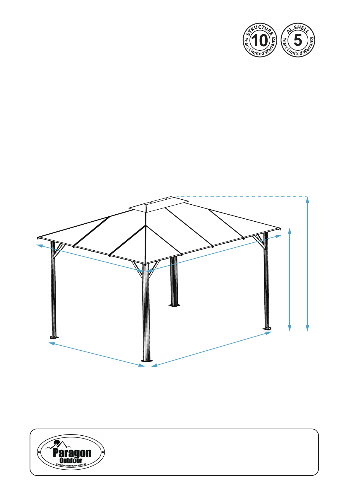
Gazebo GZ3584-1
Aluminum Composite Roof Panels
Assembly Instructions
10’8’’
9’9’’
13’1’’
12’3’’
9’4’’
7’
Paragon Group USA
Customer Service:(877) 782 4482 Email:cs-outdoors@paragongroupusa.com

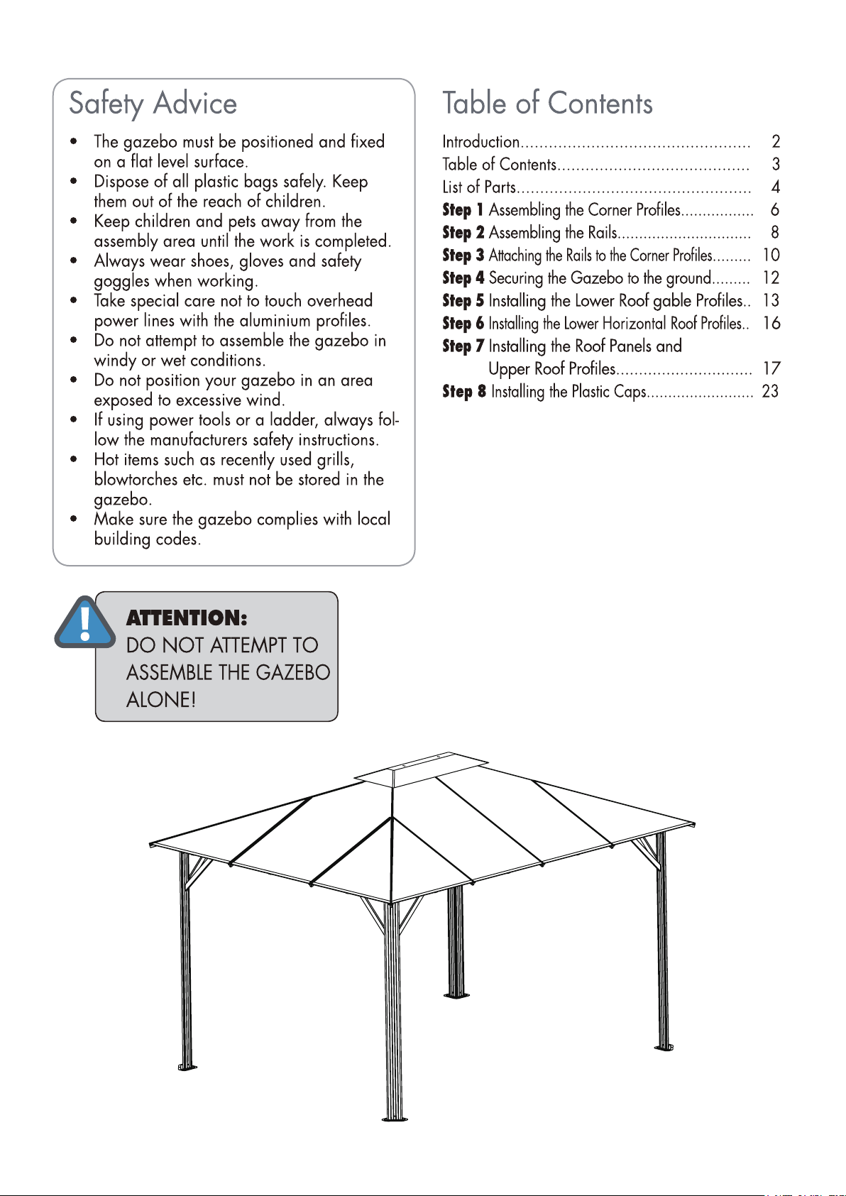
Introduction
Thank you for purchasing the Gazebo GZ3584-1.
When properly assembled and maintained, this gazebo will provide many years of enjoyment!
These instructions include helpful hints and important information needed to safely assemble and properly
maintain the gazebo. Please read these instructions completely before you begin.
Our patented gazebo has been designed for easy assembly. All steps can be completed by a team of
four people. The assembly should take about two hours.
Before Starting Assembly:
CAREFULLY READ ALL THE INSTRUCTIONS BEFORE YOU BEGIN AND FOLLOW THE
STEPS IN THE ORDER THEY ARE PRESENTED.
1. Make sure you have all the necessary parts:
Compare the contents of all cartons to the List of Parts. If any parts are missing or damaged, or
you have any questions, please contact Customer service:
2. Lay the parts out in separate staging areas:
The List of Parts has the corresponding step number referenced to each part. We recommend that
while you go through the list, make staging areas for each step and place the parts necessary for
each step in these areas. This will save you time and effort during assembly.
(877)782 4482
before beginning assembly.
3. Select a Location:
When selecting a location for your gazebo, a flat level area is essential and if possible with proper
water drainage and easy access to power and water, if neccessary.
Choose a sunny, level position away from overhanging trees and power lines and protected from the
wind as much as possible. Locate underground pipes or cables before preparing the site or anchoring
the gazebo.
Note: You may assemble the gazebo on a hard level surface and move it to its final location when
finished. Make sure that there are no obstacles between the assembly area and the final position.
4. Prepare a Foundation:
After choosing a location, proper preparation of the site is recommended. The site must be level.
If the site is not level, create a base slightly
perimeter of two by fours filled with either soil, sod or gravel.
Make sure the base is square by measuring the diagonals from both directions and making sure
they are equal. The gazebo is secured with pegs into holes cast with concrete.
If you decide to have a concrete base, it is best to contact a reliable contractor to make sure it is flat
and level. Make sure you have checked with your local authorities regarding any required building
permits.
larger than the outside dimensions of the gazebo using a
5. Make sure you have the proper tools:
• Tape Measure • 2 Small Step Ladders
• Work Gloves • Wooden Mallet
• Safety goggles • Scissors and knife
• Phillips Screwdriver • Liquid soap or WD40 Lubricant
• Spirit Level
NOTE: A cordless drill with Phillips head bit is highly recommended but not essential.
2 of 24
of 243
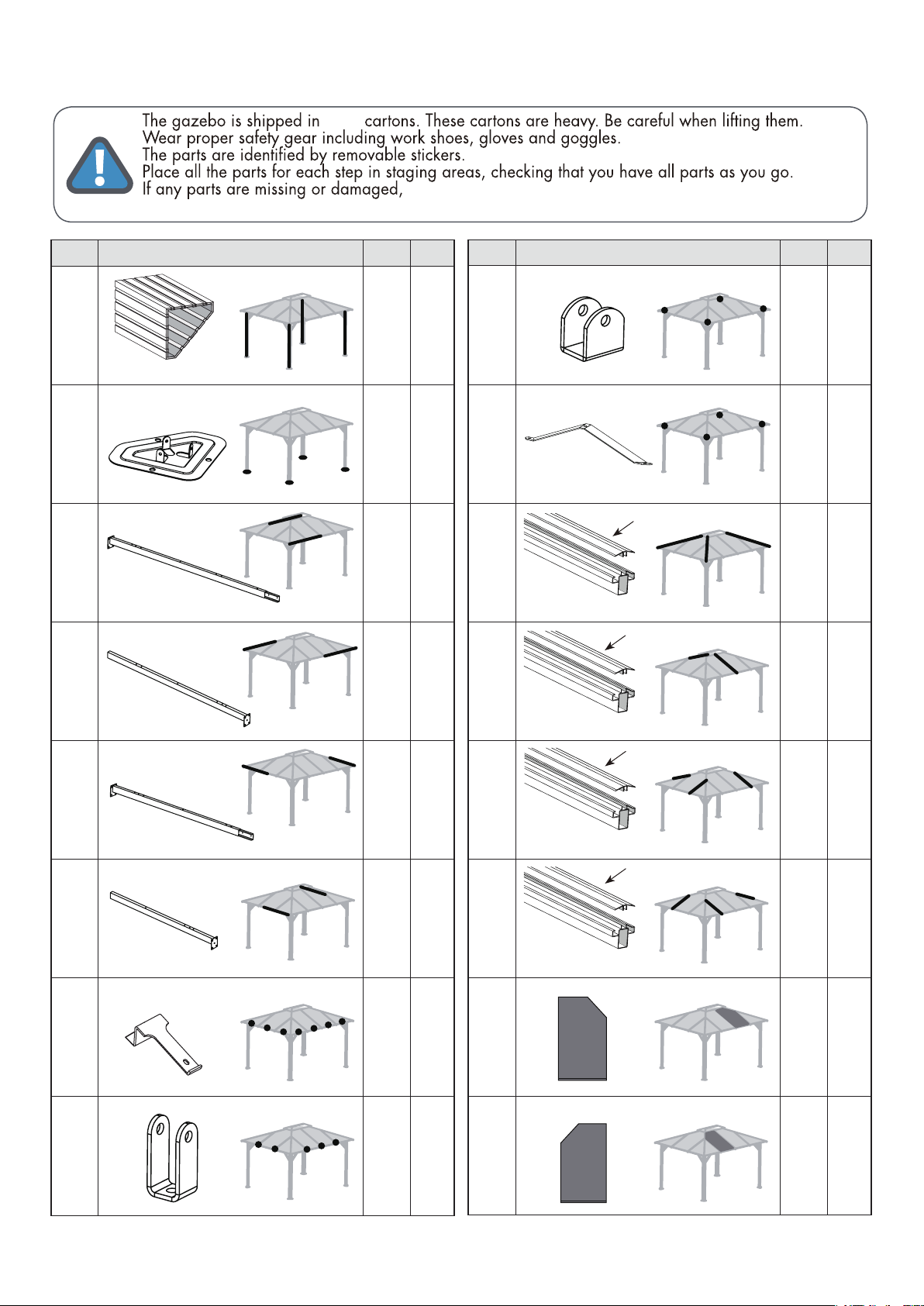
List of Parts
Customer Service:(877) 782 4482 Email:cs-outdoors@paragongroupusa.com
three
contact customer service before beginning assembly:
No. Part Qty Step
1 4
2200mm
2 4
3 2
1978mm
4 2
1
1
2
2
No. Part Qty Step
9 4
10 4
11A
2092mm
11 4
2346mm
12A
1530mm
12 2
4
4
6
6
1629mm
5 2
1639mm
6 2
1228mm
7 14
8 10
2
2
4
4
1696mm
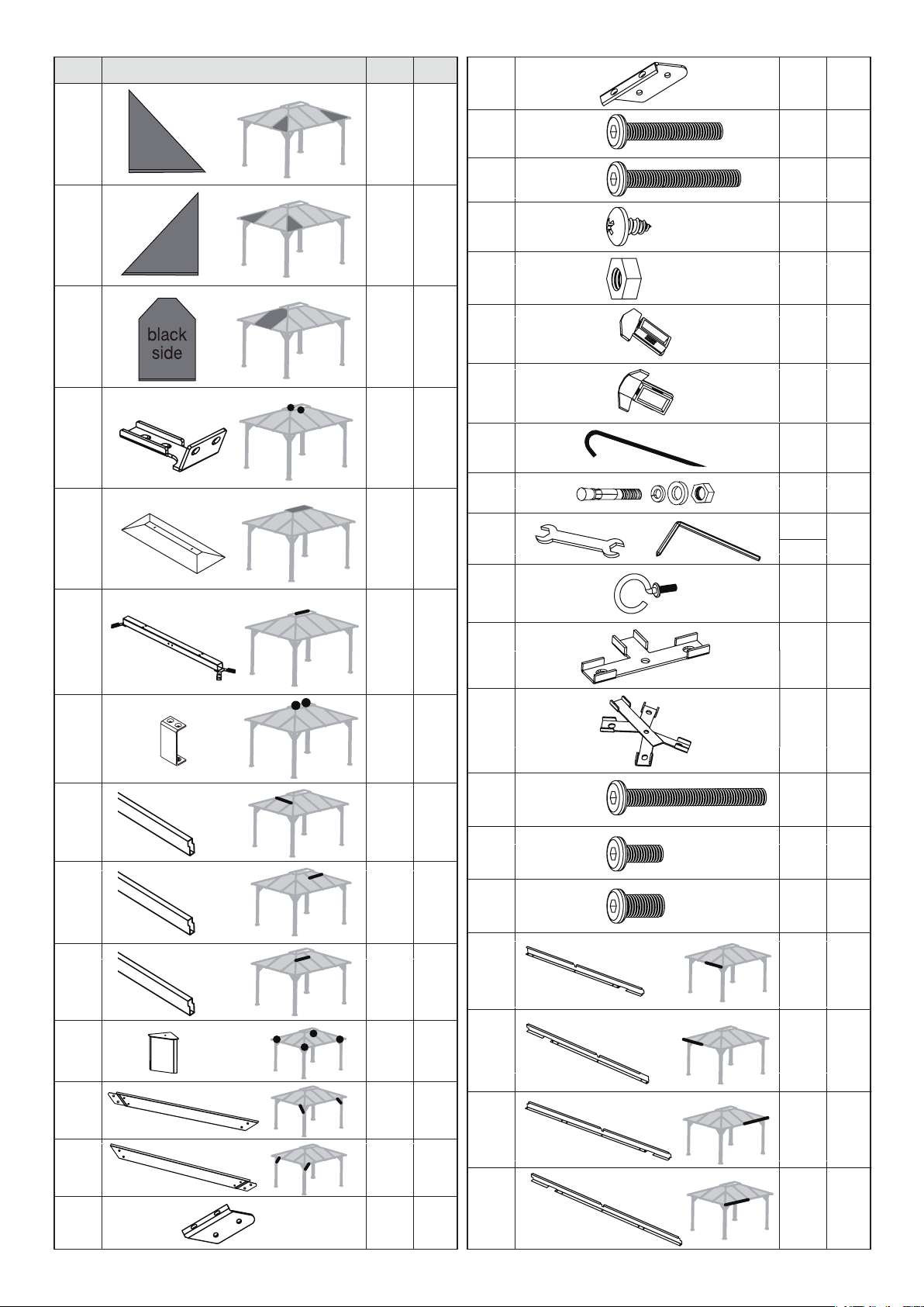
13A
1154mm
13
1164mm
14A
1154mm
14 4
1164mm
15 2
16 2
black
side
black
side
4
6
6
8
8
of 244
No. Part Qty
Step
31 4
4
17 4
18 4
black
side
black
side
19 2
20 2
21 1
8
32 66
M6*38mm
33 4
M6*45mm
8
8
34 14
M4*8mm
35 16
M6
37 10
38 4
6
39 12
40 12
6
6
8
6
9
9
5
5
1
6
41
1
22 1
23 2
24 2
25 2
26 2
42 1
7
6
43 2
6
44 4
45 2
7
M6*55mm
46 164
M6*15mm
7
47 32
M8*15mm
48 2
6
6
6
1,2,4
6,7
3
4
7
1419mm
27 4
28 4
29 4
30 4
1
49 2
1419mm
4
4
50 2
1754mm
4
4
4
51 2
1754mm
of 245
We included some extra screws and bolts for your convenience.
4
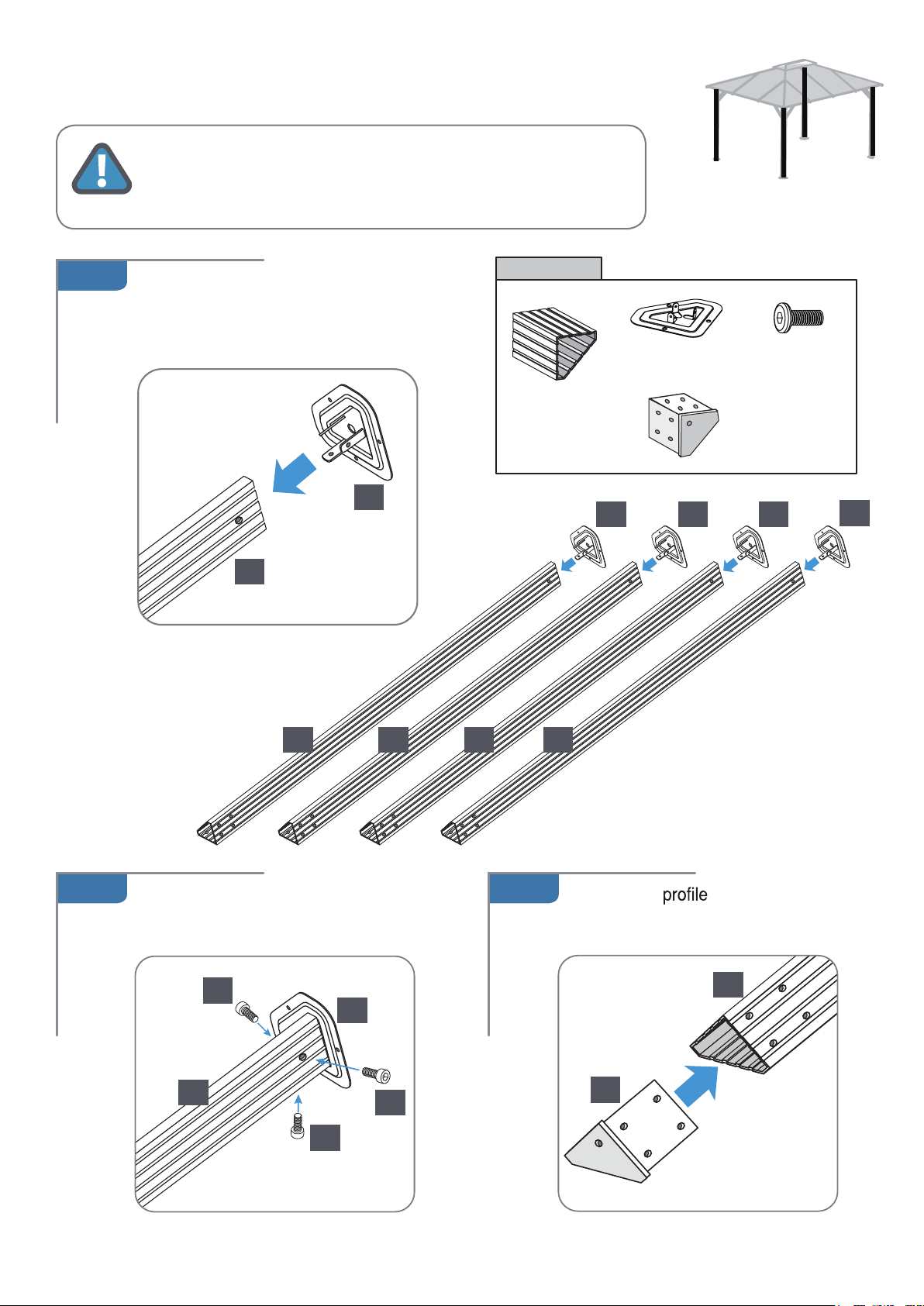
STEP 1
Assembling the Corner Profiles
1.A
Place all the parts on a level surface
Make sure the pieces are in the correct positions before assembling.
Carefully follow the order of assembly to ensure an easy installation.
Wear proper safety gear including work shoes, gloves and goggles.
Place corner profiles (1) parallel to each other
on the ground. Slide support plates (2) into
corner profiles from the end with a single
screw hole, as shown.
1
.
Components
Corner profile (1)
x 4
2
x 4
Support plate (2)
x 4
Corner profile
cover (27)
x 4
2 2 2
Screw (46)
x 12
2
1 1 1 1
1.B 1.C
Fasten each plate to profile using
three screws (46).
46
2
1
46
46
x 4
Insert corner covers (27)
into top ends of corner profiles (1)
as shown.
1
27
x 4
of 246
5
5
5
5
5
5
5
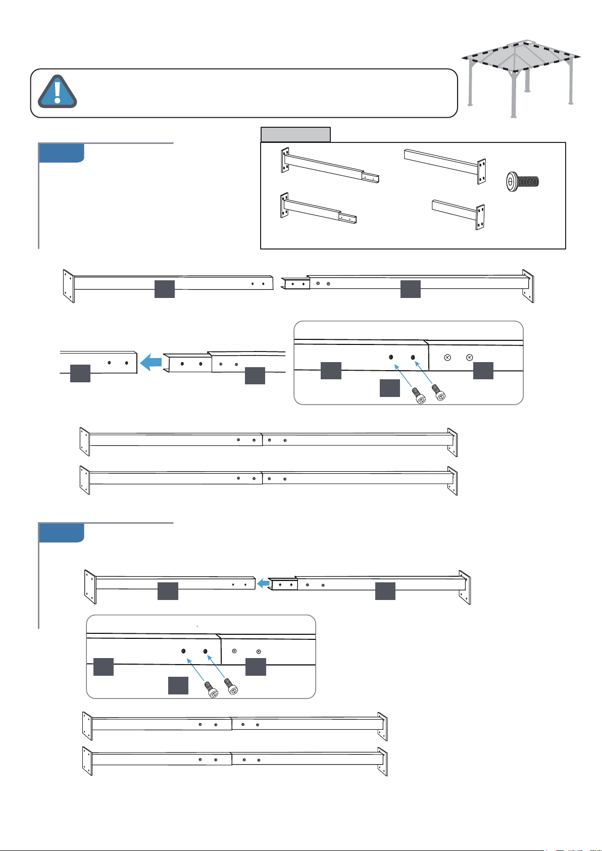
STEP 2
Place all the parts on a level surface. Make sure the pieces are in the correct positions
before assembling. Carefully follow the order of assembly to ensure an easy installation.
Wear proper safety gear including work shoes, gloves and goggles.
Assembling the Roof Profiles
Components
2.A
Insert end of long roof profile (3)
into long roof profile (4) as shown.
Fasten with screws (46).
Repeat to make two sets.
4
4
Roof profile (3)
x 2
Roof profile (5)
x 2
3
4
Roof profile (4)
x 2
Roof profile (6)
x 2
3
46
2121212121
Screw (46)
x 8
3
2.B
x 2
Insert end of short roof profile (5) into short roof profile (6) as shown. Fasten with screws (46).
Repeat to make two sets.
5
56
6
46
2121212121
5
x 2
of 247
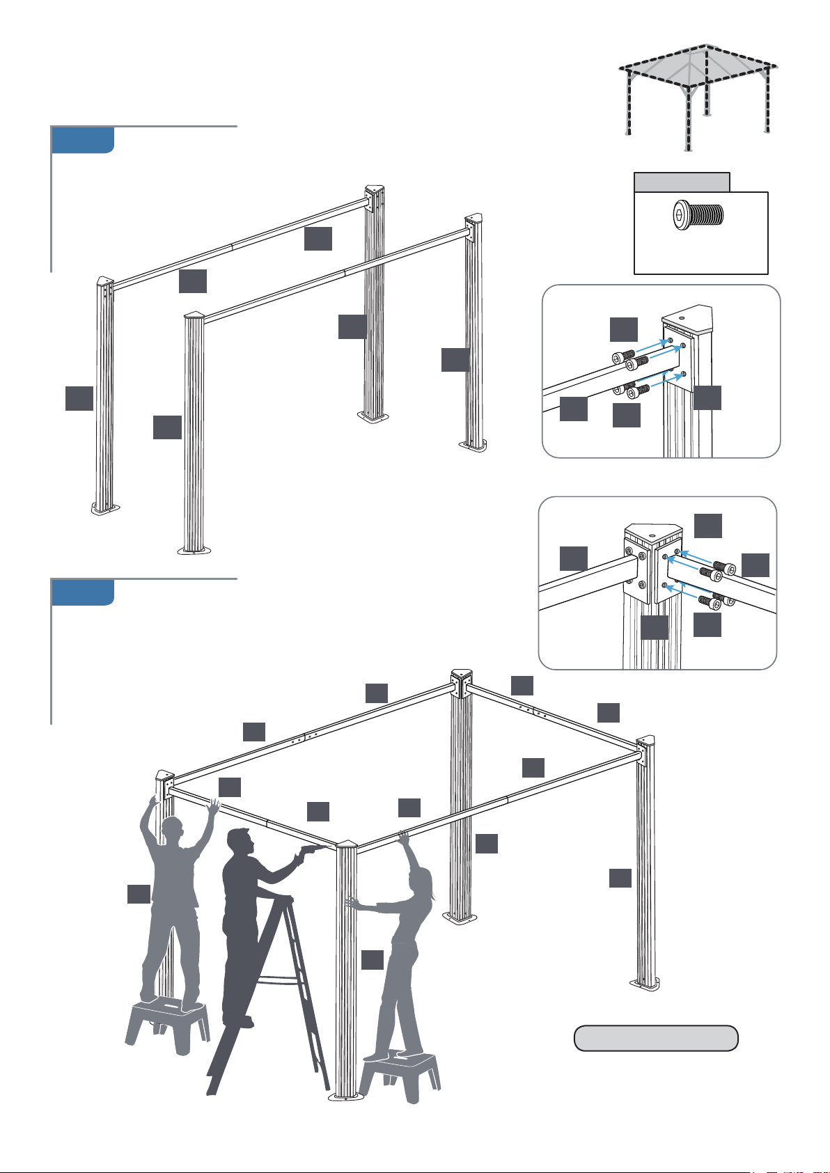
STEP 3
Attaching Roof Profiles to
Corner Profiles
3.A
1
4
1
roof profile
sets (3,4) to corner profiles (1) as shown.
Attach long
Fasten with screws (47).
Repeat to make two sets.
Components
3
1
1
4
47
47
Screw (47)
x 32
1
27
3.B
Attach short roof profile sets (5,6) to corner profiles (1)
as shown.
Fasten with screws (47).
3
4
5
6
1
3
1
3
1
6
5
4
1
1
47
6
ILLUSTRATION
of 248
 Loading...