

Page 1

EC72, EC72D
GENERAL INSTRUCTIONS
http://waterheatertimer.org/Paragon-timers-and-manuals.html#EC
Replacement timer
http://waterheatertimer.org/Intermatic-ET-series-timers-and-manuals.html#ET1700
Page 2

MAPLE CHASE COMPANY PRODUCT WARRANTY
The products manufactured by Maple Chase Company and used in commercial, industrial or institutional applications are warranted to be free from defects
in workmanship or material under normal use and service for a period of one
(1) year from the date of purchase by the end user (whether separately or as a
component of other products), or eighteen (18) months from the date of manufacture of the Maple Chase Company products, whichever is less.
Maple Chase’s obligation under this warranty is limited to replacing or repairing, free of charge, any product returned to Maple Chase with transportation
charges prepaid, providing that Maple Chase’s examination discloses to its
satisfaction that such product is defective.
This warranty does not apply to damage caused by misuse, neglect, accident
or mishandling, or to products which have been subject to repair by anyone
other than Maple Chase Company, opened or taken apart, or which have not
been properly installed or have been used other than in accordance with Maple
Chase’s instructions.
THIS WARRANTY IS IN LIEU OF ANY OTHER WARRANTY, EITHER
EXPRESS OR IMPLIED, INCLUDING BUT NOT LIMITED TO ANY IMPLIED
WARRANTY OR MERCHANTABILITY OR FITNESS FOR ANY PARTICULAR
PURPOSE.
IN NO EVENT SHALL MAPLE CHASE COMPANY BE LIABLE TO PURCHASER OR ANY THIRD PARTY FOR ANY LOSS OF PROFITS OR OTHER
INCIDENTAL, CONSEQUENTIAL OR SPECIAL DAMAGES WHATSOEVER.
PRODUCT IMPROVEMENTS
Maple Chase Company reserves the right under its product improvement policy to change construction or design without obligation regarding previous
models, and furnish equipment when so altered without reference to illustrations or specifications used herein.
2
Page 3

CONTENTS
INTRODUCTION . . . . . . 5
PROGRAMMING CAPABILITIES. . . . . . 6
SPECIFICATIONS . . . . . . 7
EC72 INSTALLATION, BATTERY and WIRING . . . . . 11
EC72D INSTALLATION, BATTERY and WIRING . . . . . 14
FRONT PANEL DESCRIPTION. . . . . 19
GENERAL PROGRAMMING INSTRUCTIONS . . . . . 20
MOMENTARY OPTION . . . . . 22
PROGRAMMING TIME, DAY, and DATE . . . . . 24
PROGRAMMING EVENTS . . . . . 26
OVERRIDE . . . . . 29
PROGRAMMING HOLIDAYS. . . . . 30
MAINTENANCE . . . . . 33
APPLICATIONS . . . . . 34
TROUBLESHOOTING . . . . . 45
GLOSSARY . . . . . 46
INDEX . . . . . 47
3
Page 4

4
Page 5

EC72, EC72D
Electronic Time Controls
DESCRIPTION
The EC72 and EC72D are seven-day, two-channel time controls that
will switch two different electrical circuits according to a pre-set, timeof-day program, thus providing precise control of those circuits from a
central location and common time base. Once programmed, the controls will automatically turn loads ON and OFF according to your
schedule, compensating for changes in Daylight Savings Time, adjusting for Leap Year and altering ON/OFF events on designated holidays.
APPLICATIONS
The EC72 Series provides ideal control for indoor and outdoor lighting,
heating, ventilation and air conditioning, and motors, pumps and fans
in convenience and retail stores, commercial buildings, industrial facilities, schools and churches. The Momentary Option, accessed by clipping a jumper wire, provides a two-second momentary contact closure
ideal for ringing school bells and church chimes or operating latching
relays. The 12-volt DC model is ideal for battery-powered applications
such as security systems, remote deer feeders and air sampling
machines.
Both Models possess identical programming capabilities. The differences between the controls lie in housing - the EC72 is enclosed in a
NEMA 1 indoor metal case, while the EC72D is a DIN model, housed
in an indoor plastic case.
5
Page 6

The EC72D typically is used in indoor or outdoor panels. The EC72 is
used for indoor stand-alone applications.
PROGRAMMING CAPABILITIES
• True 7-Day Programming - each day of the week can be uniquely
programmed.
• 16 Events per Channel - up to 16 ON/OFF events can be pro-
grammed for each channel.
• Repeat Programming - simplifies programming and increases the
total number of events through daily repetition of certain ONs and
OFFs; creates a maximum of 112 events per week per channel.
• Holiday Programming - twelve single-day holidays and two holiday
durations are programmable by date.
• Daylight Saving Time - can be programmed for automatic
changeover in the spring and fall.
• Automatic Leap Year Correction
• Momentary Option - any EC72 Series model can be converted to a
momentary output control by clipping a jumper wire; all events
become ON events of two-second duration. (See page 22.)
• Manual Override - temporarily reverses current output state; begins
immediately when initiated and remains in effect until overridden
again or until the next programmed event; each channel can be overridden independently.
6
Page 7

SPECIFICATIONS
ELECTRICAL
Power Requirements
MODEL VOLTAGE HERTZ VA REQ.
EC72/24 24 Vac (+ 10 - 15%) 50/60 4
EC72/120 100-120 Vac 50/60 4
EC72/240 200-240 Vac 50/60 4
EC72/277 277 Vac 50/60 4
EC72D/12 12 Vdc — —
EC72D/24 24 Vac (+ 10 - 15%) 50/60 4
EC72D/120 100-120 Vac 50/60 4
EC72D/240 200-240 Vac 50/60 4
Output - Two SPDT relays with contacts rated as follows:
VOLTAGE RESISTIVE INDUCTIVE H.P. PILOT DUTY
12 Vdc .1A-15 a — — —
24 Vac 15 A 15 A 1/10 60 VA
120 Vac 15 A 15 A 1/3 345 VA
240 Vac 10 A 8 A 1/2 450 VA
277 Vac 10 A 8 A — 450 VA
Wiring - Terminals can accommodate 14 to 24 AWG wire.
ACCURACY
Time-of-day - Maintained time is as accurate as line frequency.
Resolution - One minute for time-of-day and programmed ON/OFF
events.
7
Page 8

SPECIFICATIONS continued
POWER OUTAGE CARRYOVER
Program and Time-of-Day Backup - 100 hours of carryover with a 9-
volt alkaline battery. 275 hours of carryover with a 9-volt lithium battery (Ultralife, U9VL.) Battery not provided. During a power outage, the
time and program are maintained, but the output relays remain deenergized.
ENVIRONMENTAL
The EC72 Series should be mounted indoors in an environment that is
free from excessive contaminants such as oil, moisture and dirt or in
an appropriate outdoor panel. For outdoor use, an EC72D can be
mounted in a NEMA 3 enclosure 4010EC (X9092) which must be purchased separately.
PHYSICAL
Mounting
EC72D — Surface or DIN-rail (35mm, DIN-EN50022) with plug-in base
EC72 — NEMA 1 case mounting
Weight — EC72D — Approximately 1 lb 3 oz (0.54 kg)
EC72 — Approximately 2 lb (0.90 kg)
Dimensions - EC72D — Width 10.5 cm (4 1/8")
Height 10.5 cm (4 1/8")
Depth 7.6 cm (3")
* EC72 — Width 10.8 cm (4 1/4")
Height 20.0 cm (7 7/8")
Depth 7.6 cm (3")
* outside dimensions, including hinge and bracket
8
Page 9
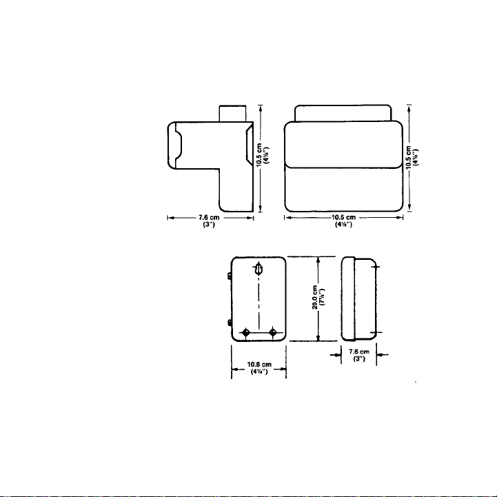
Figure 1. EC72 Series Dimensions
9
EC72
EC72D
Page 10
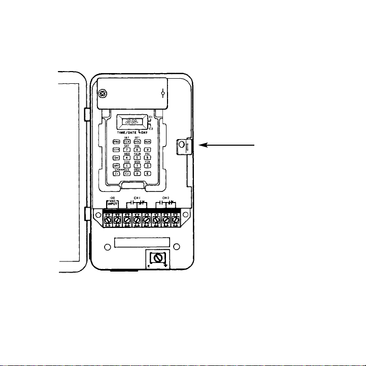
Figure 2. EC72 Installation
10
Spring
Clip
Page 11

INSTALLATION - EC72
NEMA 1 Case Mounting
1. Press back on spring clip at right center of metal case. See Figure
2 at left. Lift control out and set aside.
2. Remove desired knockouts to provide wiring access.
3. Mount case in a vertical position using the mounting holes provided.
4. Replace control by inserting tabs on left side of front panel into
slots on left side of case. Push down and snap into place.
5. Connect an electrical ground to grounding terminal screw located
inside the metal case bottom. See Figure 2 at left.
11
Page 12

BATTERY - EC72
Installation — Purchase a 9-volt alkaline or lithium battery (Ultralife,
U9VL).
Remove battery cover by pulling up right side of cover from the extru-
sion that holds it. Swivel battery cover up and out of the way. Snap battery into battery clip. Mark date on battery log. Replace battery cover.
Figure 3. EC72 Battery Cover Removal
Replacement —
Alkaline, approximately every 2 years.
Ultralife U9VL, approximately every 5 years.
A battery log is provided inside the battery cover to record battery
replacement dates.
12
Page 13
WIRING — EC72
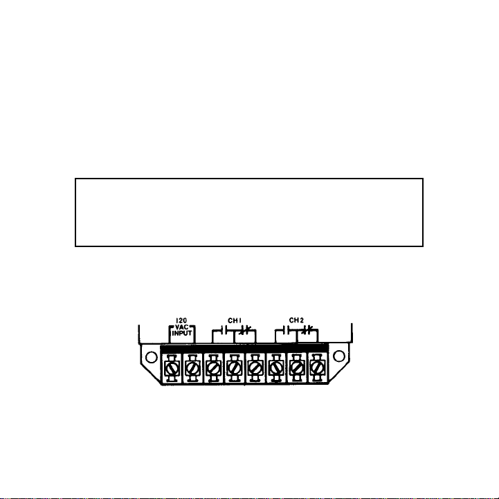
1. Remove the gray fish paper insulator card in order to provide
access to the terminal block. Wiring access for power input and
relay output is provided at bottom of terminal block. Terminals can
accommodate 12 to 24 AWG wire.
2. Wire 12 Vdc, 24, 120, 240 or 277 Vac to terminals 1 and 2. See
Figure 4 below. Determine voltage according to the model selected.
3. Connect output wiring as required for the particular application.
See wiring diagrams on pages 34-44.
4. Make sure that all wiring is in accordance with national and local
electrical codes.
Figure 4. EC72 Terminals
13
CAUTION: Damage will occur to unit if incorrect
voltage is applied. Application of incorrect input
voltage will void warranty. See product label to
make sure you are applying the correct voltage.
Page 14
INSTALLATION — EC72D
EC72D Surface Mounting
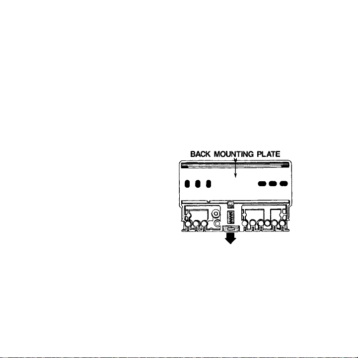
1. Remove back mounting plate by releasing the bright red springloaded catch. See Figure 5 below.
2. Install back mounting plate on a vertical or horizontal surface, flush
side to panel or wall. Utilize the mounting holes on the back
mounting plate. (Screws are not provided.)
3. Pull down on spring-loaded catch and snap control onto back
mounting plate.
Figure 5. EC72D Back
EC72D and EC72E DIN Rail Mounting
1. Remove back mounting plate by releasing spring-loaded catch.
See Figure 5 above. Store or discard mounting plate.
2. Snap base connection block onto DIN-rail.
14
Page 15

BATTERY — EC72D
Installation - Purchase a 9-volt alkaline or lithium battery (Ultralife,
U9VL).
Remove battery cover by pressing sides together and pulling left or
right. See Figure 6 below.
Snap battery into battery clip. Mark date on battery log. Replace bat-
tery cover.
Figure 6. EC72D Battery Cover Removal
Replacement —Alkaline, approximately every 2 years.
Ultralife U9VL, approximately every 5 years.
A battery log is provided inside the battery cover to record battery
replacement dates.
15
Page 16

WIRING - EC72D
1. Loosen terminal cover screw (see Figure 7) and set terminal cover
aside. The screw is captive to the control. Wiring access for power
input and relay output is provided at bottom of terminal block.
Terminals can accommodate 12 to 24 AWG wire.
2. Wire 12 Vdc or 24, 120 or 240 Vac to terminals 1 and 2. See Figure
7 at right. Determine voltage according to the model selected.
3. Connect output wiring as required for the particular application.
See pages 34-44 for wiring diagrams.
4. Cut out terminal cover for wiring. Cutting guides are molded in the
inside bottom of the cover.
5. Replace terminal cover and tighten terminal screw.
6. Make sure that all wiring is in accordance with national and local
electrical codes.
16
CAUTION: Damage will occur to unit if incorrect voltage
is applied. Application of incorrect input voltage will void
warranty. See product label to make sure you are applying the correct voltage.
Page 17

Figure 7. EC72D Terminals
1. Contacts are shown in the OFF, or de-energized, state.
2. Maple Chase Company’s solid state controls utilize DRY CONTACTS. Input power enables the control to keep time, store programmed information and carry out instructions, but input power
does not power the loads. In order to make the circuits functional,
you must provide power to the contacts as shown in the wiring diagrams on pages 34-44.
17
Page 18

Figure 8. EC72 Series Keypad and Screen
18
Page 19

FRONT PANEL DESCRIPTION
The keypad and screens on all EC72 Series controls are identical. On
the EC72, however, the screen is located above the keypad, while on
the EC72D, the screen is located to the left of the keypad.
1 Time/Date Indicator — displays hours and minutes in 24-
hour format (e.g., 00:00=midnight, 12:00=noon,
23:00=11:00 PM) or month and date for current day or an
event being programmed or reviewed (101=January 1).
Day of Week Indicator — displays current day of week or
day being programmed or reviewed (Sunday=1, Monday=2,
Tuesday=3, Wednesday=4, Thursday=5, Friday=6,
Saturday=7, Holiday=8, Daily=0).
Channel Indicators — bar(s) appear when channel(s)
C1/C2 are energized.
2 Mode Keys — PRG, CLK, HOL, RUN — used to select
mode of operation.
3 Number/Day Keys — used to program time, day, month,
date and year.
4 Clear Key — must be used to clear an old entry before a
new one can be entered; also used to clear errors.
5 ON/OFF Keys — used to select an ON or OFF event.
6 Channel Keys — used to select Channel 1 or 2 (C1/C2) for
programming or review; also used to initiate manual override.
7 Enter Key — used to enter a new event or to review
program.
19
Page 20

BEFORE YOU BEGIN PROGRAMMING…
Make sure you understand the programming capabilities of your control:
7-Day Programming
Each day of the week can be uniquely programmed. In other words,
the schedule of ON/OFF events can vary for each day of the week —
e.g., 10:00 AM ON Monday, 8:00 AM ON Tuesday — Thursday, 7:00
AM ON Friday, 12:00 noon ON Saturday, etc. Whatever schedule is
programmed will be repeated weekly, with the same ONs and OFFs
every Monday, every Tuesday, etc.
16 Events per Channel
An event is a single change in operation; i.e., switching ON or switching OFF. Up to 16 ON/OFF events can be programmed for each channel — a maximum of 8 ONs and 8 OFFs for Channel 1 and 8 ONs and
8 OFFs for Channel 2.
If one ON and one OFF is assigned to each day of the week — at differ-
ent times each day — then 14 events would be used (7 days x 2
events/day). The remaining ON and OFF for that channel could then be
assigned to the Eight Day — or Holiday Program — discussed on the
next page.
If one or more ON/OFF event occurs at the same time every day, then
that event is a Daily Event and uses only one of the 16 available
events. See Repeat Programming on the next page.
Momentary Option
Any EC72 Series model can be converted to momentary output. This
decision should be made prior to programming. See pages 22-23 for
more information.
20
Page 21

Repeat Programming
Repeat Programming simplifies programming and increases the total
number of events through daily repetition of certain ONs and OFFs.
For example, say that a certain event will occur at the same time every
day — e.g., 8:00 AM ON. Rather than programming 8:00 AM ON
Monday, 8:00 AM ON Tuesday, 8:00 AM ON Wednesday, etc., the Daily
Key can be used, causing the event to be repeated each and every
day of the week and using only one of the 16 available events. The
remaining 15 events can be used to create additional daily ONs and
OFFs or they can be used to create unique once-a-week events; e.g.,
6:00 PM ON Wednesday only.
At least one ON and one OFF should be reserved for Holiday
Programming. See below.
Repeat Programming creates a maximum capacity of 112 events per
week per channel (16 events/channel x 7 days).
Holiday Programming
Twelve single-day holidays and two holiday durations are programmable by date. The Eighth Day, or Holiday, Program will repeat the same
special schedule on each of the holidays assigned to it — whether that
schedule includes one or more events or no events.
Holiday Programming includes two steps:
1. Telling the control which days should be included in the holi-
day schedule (see page 30); and
2. Programming the events that should occur on those holi-
days or informing the control that no events should occur.
(See page 24.)
21
Page 22

MOMENTARY EVENT OPTION
The Momentary Option provides a two-second momentary contact
closure that is ideal for ringing school bells and church chimes or utilizing latching relays. Any EC72 Series model can be converted to
momentary output by clipping a jumper wire, which causes all events
to become ON events of two-second duration.
Three changes take place when the jumper is clipped:
1. Determining whether an event should be an ON or OFF event is unnecessary, since all events become ON events of two-second duration.
2. When Manual Override is used on either channel, the relay for
that channel will be energized for two seconds.
3. Channel indicator bars are not displayed when relays energize.
See Applications at the back of this book for further information.
To convert EC72 to a momentary output control:
1. Disconnect all power to control.
2. Remove control from the metal case as described in Step 1 on
page 11.
3. Clip the jumper wire, J1, located on the back side of the control
unit in the upper left-hand corner of the green board. See Figure 9,
if date code on circuit board is before Dec. 1987. If date code is
after Dec. 1987, see Figure 9A.
22
FIGURE 9.
EC72 Jumper Wire
Page 23

To convert the EC72D:
1. Remove the control according to directions on page 17.
2. The jumper wire, J29, is located on the back side of the control in
the upper left-hand corner of the board. See Figure 10 below. Clip
J29.
Figure 10. EC72D Jumper Wire
23
Figure 9A.
EC72
Jumper Wire
Page 24

TO PROGRAM TIME, DAY AND DATE
Step Key Description
1. Install battery/power. 0:00 1 displayed; colon and 1
flashing.
2. CLK Flashing stops.
3. #### # Enter current time, then day of week.
Enter four digits for time (e.g., 0900=9:00 AM).
Use 24-hour clock format. See chart below.
For day of week, 1=Sunday, 2=Monday, 3=Tuesday,
4=Wednesday, 5=Thursday, 6=Friday, 7=Saturday.
4. E Enters time. 101 displayed, indicating January 1.
5. #### Enter current month, then date. Press two keys for
month and two for date (e.g., 0101=January 1).
6. E Enters month and date. 84 is displayed, indicating
1984.
7. ## Enter current year. Two keys must be pressed (e.g., 88)
8. E Enters year. Control switches automatically to run
mode. Time and day-of-week displayed. Colon flashing.
0:00=midnight 08:00=8:00 AM 16:00=4:00 PM
01:00=1:00 AM 09:00=9:00 AM 17:00=5:00 PM
02:00=2:00 AM 10:00=10:00 AM 18:00=6:00 PM
03:00=3:00 AM 11:00=11:00 AM 19:00=7:00 PM
04:00=4:00 AM 12:00=noon 20:00=8:00 PM
05:00=5:00 AM 13:00=1:00 PM 21:00=9:00 PM
06:00=6:00 AM 14:00=2:00 PM 22:00=10:00 PM
07:00=7:00 AM 15:00=3:00 PM 23:00=11:00 PM
In 24-hour format, minutes remain the same (e.g., 13:35 = 1:35 PM).
24
Page 25

To Review Date
Step Key Description
1. CLK Current time displayed. Flashing stops.
2. E Current month and date displayed.
3. E Current year displayed.
4. RUN Restores normal operation. Time and day displayed.
Colon flashing.
5. C1/C2 Switching of loads occurs only in the RUN mode. If an
event was scheduled to occur while you where
reviewing information, the event will not have taken
place if you were reviewing during the entire minute
that the event was scheduled to occur. Press C1 or
C2 to initiate override if the status of either circuit is
incorrect.
This applies to programming as well as reviewing.
To Change Time, Day or Date
Step Key Description
1. CLK Currently programmed time displayed. Flashing stops.
2. #### # Enter correct time, then day of week.
3. E Enters new time. Current programmed date displayed.
4. #### Enter new month, then date if either is incorrect.
5. RUN Time and day displayed. Colon flashing.
6. C1/C2 Press C1 or C2 to initiate override if the status of
either circuit is incorrect. See above, Step 5, To
Review Date.
25
Page 26

TO PROGRAM ON/OFF EVENTS
Step Key Description
1 PRG Display goes blank except for the Channel indicator
bars, which flash alternately to indicate that a channel
number key must be pressed.
2 C1/C2 Selects channel to be programmed. C1 or C2
Indicator bar energizes and E:01 (first event) is displayed.
3 #### # Enter time, then day of week for first event. Enter four
digits for time (e.g., 0900=9:00 AM). For day of week,
1=Sunday, 2=Monday, 3=Tuesday, 4=Wednesday,
5=Thursday, 6=Friday, 7=Saturday, 8=Holiday,
0=Daily.
If no events are desired on a particular day — for
instance, on Day 8 (the Holiday Program) — key in
0000 for the time and — in Step 4 below — select ON
or OFF for the entire day.
4 ON/OFF Selects an ON or OFF event. Colon signifies an ON; no
colon signifies an OFF.
This step is unnecessary if you have used the
Momentary Option, since all events become ON
events.
5 E Enters programmed event into memory. Next event
slot (E:02 - E:16) displayed.
6 Repeat Steps 3 - 5 for all events on one channel. The
control will automatically switch to E:01 on the other
channel. Repeat Steps 3 - 5.
7 RUN Restores normal operation. Time and day displayed.
Colon flashing.
26
Page 27

Use the following chart to record events. Circle all days for Daily Events (Key 0).
EVENTS
C1 TYPE TIME DAY OF WEEK C2 TYPE TIME DAY OF WEEK
1 ON / OFF S M T W T F S 1 ON / OFF S M T W T F S
2 ON / OFF S M T W T F S 2 ON / OFF S M T W T F S
3 ON / OFF S M T W T F S 3 ON / OFF S M T W T F S
4 ON / OFF S M T W T F S 4 ON / OFF S M T W T F S
5 ON / OFF S M T W T F S 5 ON / OFF S M T W T F S
6 ON / OFF S M T W T F S 6 ON / OFF S M T W T F S
7 ON / OFF S M T W T F S 7 ON / OFF S M T W T F S
8 ON / OFF S M T W T F S 8 ON / OFF S M T W T F S
9 ON / OFF S M T W T F S 9 ON / OFF S M T W T F S
10 ON / OFF S M T W T F S 10 ON / OFF S M T W T F S
11 ON / OFF S M T W T F S 11 ON / OFF S M T W T F S
12 ON / OFF S M T W T F S 12 ON / OFF S M T W T F S
13 ON / OFF S M T W T F S 13 ON / OFF S M T W T F S
14 ON / OFF S M T W T F S 14 ON / OFF S M T W T F S
15 ON / OFF Holiday (Key 8) 15 ON / OFF Holiday (Key 8)
16 ON / OFF Holiday (Key 8) 16 ON / OFF Holiday (Key 8)
27
Page 28

TO REVIEW OR CHANGE EVENTS
Step Key Description
1 PRG Display goes blank except for Channel indicator bars,
which flash alternately to indicate that a channel number key must be pressed.
2 C1/C2 Select channel to be reviewed. Selected Channel
Indicator bar will energize. The first programmed event
will be displayed. If the first event has not programmed
event will be displayed.
3 E Press repeatedly to review all 16 events for one chan-
nel, followed by all 16 events for the other channel.
4 CLR Press if any displayed time and/or day must be
changed.
5 #### # Enter correct time and day.
6 RUN Restores normal operation. Time and day displayed.
Colon flashing.
7 C1/C2 Switching of loads occurs only in the RUN mode. If an
event was scheduled to occur while you where
reviewing or programming information, the event will
not have taken place if you were reviewing or programming during the entire minute that the event was
scheduled to occur. Press C1 or C2 to initiate override
if the status of either circuit is incorrect.
28
Page 29

NOTES ON EVENTS
The weekday keys 1 - 7 and the holiday key 8 have priority over the
daily key 0. If an ON/OFF event is programmed for an individual
weekday, then all programmed daily events are cancelled for that day
on that channel. For example, if you program a daily On at 8:00 AM
and a daily OFF at 5:00 PM, and then program an ON to occur only
on Wednesday at 10:00 AM, the ON at 8:00 and OFF at 5:00 will be
cancelled out; you will need to program a separate OFF for
Wednesday.
You can program daily events and still skip a day by programming an
event with 0000 for the time on that day. For instance, say that you
want an 8:00 AM ON and 5:00 PM OFF for each weekday, but you
wish to skip both Saturday and Sunday. Program the ON and OFF as
daily events and then program a 0000 event for each Saturday and
Sunday. See Step 3 on page 26. This process, however, cannot be
used if the control has been converted to momentary output; if you
have selected the Momentary Option, there is no way to use the daily
function and also skip any day(s) — all daily events will occur everyday. In some applications, this can be overcome by external wiring.
See page 42.
OVERRIDE
To initiate override, the control must be in the RUN mode. Press C1
and/or C2 to override desired channel from ON to OFF, or OFF to
ON. Channel remains in that state until overridden again or until the
next opposite programmed event. If control has been converted to
momentary output, initiating override will energize the relay(s) for two
seconds.
29
Page 30

HOLIDAY and DAYLIGHT SAVINGS TIME
Twelve single holidays (H:01 - H:12) and two holiday durations
(H:13 - H:16) are provided. Fill in the chart at right before you begin.
Step Key Description
1 HOL H:01 displayed, indicating Holiday 1.
2 #### Enter month, then date of holiday. Press two keys for
month and two for date.
3 E Enters holiday into memory and advances to next holi-
day. Repeat steps 2 and 3 until all single holidays
through H:12 are programmed.
4 E H:13 displayed, indicating begin date for first holiday
duration.
5 #### Enter month, then date that holiday duration will
begin.
6 E H:14 displayed, indicating end date for first holiday
duration.
7 #### Enter month, then date that holiday duration will end.
8 Repeat steps 4 - 7 for second holiday duration. H:15
denotes begin date; H:16 denotes end date.
9 E Displays SPr, indicating start date for Spring Daylight
Savings Time changeover.
10 #### Enter month, then date of spring changeover.
11 Repeat steps 9 and 10 to program Fall Daylight
Savings Time changeover. Control displays FaLL.
12 RUN Restores normal operation. Time and day displayed.
Colon flashing.
Refer to page 26 for ON/OFF events for HOLIDAYS.
30
Page 31

Use the following chart to record days that will follow the holiday schedule:
HOLIDAYS
NO. DATE DESCRIPTION
H:01
H:02
H:03
H:04
H:05
H:06
H:07
H:08
H:09
H:10
H:11
H:12
H:13 Duration 1 begins H:14 Duration 1 ends
H:15 Duration 2 begins H:16 Duration 2 ends
SPR FALL
31
Page 32

To Review or Change Holidays
Step Key Description
1 HOL Date of first holiday (H:01) displayed.
2 E Press repeatedly to review single day holidays, H:01 -
H:12. Press again to review H:13 - H:15, indicating the
begin dates for both holiday durations. No colon will
appear for H:14 and H:16, the duration end dates.
Press again to review Daylight Savings Time dates.
3 CLR Press this key if you discover that any date is incor-
rect. The title of the cleared holiday (H:01 - H:16) or
Daylight Savings Time date (Spr or FaLL) will be displayed.
4 #### Enter correct month and date.
5 E Enters new date into memory and advances to next
holiday.
6 RUN Time and day of week displayed. Colon flashing.
7 C1/C2 Switching of loads occurs only in the RUN mode. If an
event was scheduled to occur while you were programming, the event will not have taken place if you
were programming during the entire minute that the
event was scheduled to occur. Press C1 or C2 to initiate override if the status of either circuit is incorrect.
32
Page 33

MAINTENANCE
Cleaning — Do not use any type of cleaning agent on the liquid
crystal display screen or front panel.
Control Removal — Any model can be removed from its case.
EC72 — See directions on page 11.
EC72D — The plug-in case of the DIN model allows removal of the
control without disturbing the wiring. See pages 16-17 for terminal
cover removal, then pull the control upward to snap it from the terminal block. A moderate amount of force is required.
Figure 11. Removal of EC72D from Terminal Block
33
TERMINAL
BLOCK
Page 34

APPLICATIONS — LIGHTING
Objective: To control indoor lighting on Channel 1 and parking lot
lights on Channel 2.
Sequence of Operation:
Channel 1 — Relay contacts 3 and 4 close to turn indoor lights ON
during building’s open hours. Relay contacts 3 and 4 open to turn
indoor lights OFF during business closed hours.
Channel 2 — Relay contact 6 and 7 close to turn parking lot lights
ON. Relay contacts 6 and 7 open to turn parking lot lights OFF.
Note that wiring diagrams differ for different models. Check product
label to make sure you are using the correct wiring diagram.
Figure 12. EC72 Wiring Diagram for Indoor and Outdoor Lighting
34
Page 35

Figure 13. EC72D Wiring Diagram for Indoor and Outdoor Lighting
35
Page 36

APPLICATIONS — HVAC
Objective: To reduce utility costs by time-of-day scheduling for night
setback/setup and damper control. Use Channel 1 for daytime/nighttime thermostat, Channel 2 for damper.
Sequence of Operation:
Channel 1 — Before occupancy of the building, the HVAC system is
started when timer switches control from night thermostat to day
thermostat. At or near end of occupancy, timer transfers control of
HVAC system from day thermostat to night thermostat.
Channel 2 — Relay contacts 6 and 7 close, opening dampers during
building open hours. Relay contacts 6 and 7 open, closing dampers
during building closed hours.
Note that wiring diagrams differ for different models. Check product
label to make sure you are using the correct wiring diagram.
Figure 14. EC72 Wiring Diagram for Nighttime Setback and
Damper Control
36
Page 37

Figure 15. EC72D Wiring Diagram for Nighttime Setback and
Damper Control
37
Page 38

APPLICATIONS — SCHOOL BELLS
Objective: To ring school bells on a pre-programmed schedule. You
must select the Momentary Option and clip the appropriate jumper
wire. See pages 22-23.
Sequence of Operation:
At each scheduled event, the normally open contacts (3 and 4 for
Channel 1, 6 and 7 for Channel 2) close for two seconds, ringing
school bells. To eliminate Saturday and Sunday from daily schedule,
program one event for each channel on each of those days. The bells
will ring once on Saturday and once on Sunday at the programmed
time. If one of the alternate wiring diagrams shown on pages 42 - 43
is used, the bells will not ring when Channel 1 and Channel 2 have
events programmed for the same time as on Saturday and Sunday.
Note that wiring diagrams differ for different models. Check product
label to make sure you are using the correct wiring diagram.
38
Page 39

Figure 16. EC72 School Bell Wiring Diagram
Figure 17. EC72D School Bell Wiring Diagram
39
Page 40

APPLICATIONS — LATCHING RELAYS
Objective: To turn lights ON and OFF in conjunction with a latching
relay. User must select the Momentary Option and clip the appropriate jumper wire. See pages 22 - 23.
Sequence of Operation:
Relay contacts 6 and 7 close for two seconds to turn lights ON.
Relay contacts 3 and 4 close for two seconds to turn lights OFF.
Note that wiring diagrams differ for different models. Check product
label to make sure you are using the correct wiring diagram.
Figure 18. EC72 Latching Relay Wiring Diagram
40
Page 41

Figure 19. EC72D Latching Relay Wiring Diagram
41
Page 42

APPLICATIONS
FOR MOMENTARY CONTROL ONLY
The following wiring diagrams allow the Daily Function to be used
and still have a day without any events, even though the Momentary
Option has been selected. See page 29.
To use the Daily Function on a momentary control and still obtain a
day without any events, follow these steps:
1. Wire the control as shown below.
2. Program an event on both channels at the same time on the day
that should have no events. Both relays will energize at the same
time, canceling each other out.
Note that wiring diagrams differ for different models. Check product
label to make sure you are using the correct wiring diagram.
Figure 20. EC72 School Bell Alternate Wiring Diagram
42
Page 43

Figure 21. EC72D School Bell Alternate Wiring Diagram
43
Page 44

Figure 22. EC72
Latching Relay
Alternate Wiring
Diagram
Figure 23. EC72D
Latching Relay
Alternate Wiring
Diagram
44
Page 45

Solution
• Review programmed setpoints making sure
the day has not been skipped.
• Check input power to control.
• Ensure the clock is not in a holiday period.
• Check if manual override changes the
load’s state. If it does not, see next problem/solution.
• Check the load for proper wiring.
Remember, EC72 contacts switch only what
is applied to them (dry or isolated contacts).
• Disconnect battery and input power to the
control for 1 minute. Re-apply power and
reprogram.
• Check input power source and battery if
installed. Ensure proper connections of
wiring.
• If programming was performed (changing
clock time or entering a setpoint), the control
will not update itself. Press either C1 or C2
to override the load until the next scheduled
setpoint.
• If J1(EC72) or J29(EC72D) has been cut, the
EC72 now is fixed at a 2 second event duration. There is no indication of the type of
event since all events are now momentary.
Problem
Nothing happens when a
setpoint occurs to turn a
load ON or OFF.
Manual override does not
work.
Clock display is locked up,
garbled or meaningless.
Blank Display
Control does not operate
after programming.
When programming a setpoint, no indication of the
type of event is given.
TROUBLESHOOTING TIPS
45
Page 46

GLOSSARY
7-Day Programming —programming that repeats a schedule every
7 days
8th Day — any of a number of designated holidays that follow a
unique schedule, programmed with Key 8 instead of weekday Keys
1-7
Battery Carryover —a feature that maintains time and programming
during power outages but does not power the loads
Channel — an independently programmable output
Daily Event — an event that occurs every single day, programmed
with Key 0 instead of weekday Keys 1-7
DIN —a European-style mounting system for electrical controls; the
DIN rail is fixed to a panel, while the control is snapped onto the rail;
the control can be removed when necessary
Dry Contact —a contact that operates as a simple switch; voltage
must be supplied to the contact in order to power the load
Event —a change in operation (i.e. switching ON or OFF)
Holiday — any day that will follow a separate, unique schedule
assigned to all such days
Load —a device that receives power (e.g., lights)
Manual Override —a feature that reverses current programming;
loads that are ON turn OFF, loads that are OFF turn ON
Relay —a magnetically operated switch
Repeat Programming —a feature that employs the daily Key 0 to
increase the number of available events from 16 per channel to 112
per channel
Setpoint —a programmed entry that defines the type of event as
well as the time and the day(s) on which the event will occur
46
Page 47

INDEX
Accuracy, 7 Power requirements, 7
Application, 34 - 44 Programming Capabilities 6, 20 - 21
Back mounting plate, 14 To change programming, 25, 28, 32
Battery, 8, 12, 15 To review programming, 25, 28, 32
Channel Indicators, 19 To understand programming, 20-21
Cleaning, 33 To program Clock format, 19, 24 Date, 24
Daily events, 20, 29 Day of week, 24
Day of week, 19, 24 Daylight Savings Time, 30
Dimensions, 8, 9 Daily Events, 20, 26, 29
DIN rail, 8, 14 Events, 26
Display panel (screen), 19 Holidays, 21, 30
Dry contact, 17, 46 Time of Day, 24
Environmental, 8 Repeat Programming, 21
Glossary, 46 Specifications, 7
Holidays, 21, 30 Terminal block, 33
Input, 13, 16 Terminal cover, 16
Installation, 11, 14 Terminals, 13, 17
Keyboard description, 19 Time of day, 19, 24
Maintenance, 33 Time/Date/Day indicator, 19
Momentary Option, 5, 22-23 Troubleshooting, 45
Mounting, 11, 14 Warranty, 2
NEMA, 5, 8, 11 Weight, 8
Output, 7 Wiring, 13, 16
Override, 29 Wiring diagrams, 34-44
Power outage carryover, 8
47
Page 48

Part Number 110-703B
Maple Chase Company
2820 Thatcher Road
Downers Grove, Illinois 60515
Made in Mexico
Customer Service 800-951-5526
Technical Support 800-732-8400
ISO 9002 registered
Paragon Electric Canada, Ltd.
5785 Kennedy Road
Mississauga, Ontario L4Z 2G3
From outside North America
630-719-5500
 Loading...