

Paragon DTC 1000, DTC 600, DTC 800, DTC 100 Troubleshooting Manual
DTC 1000, 800, 600 & 100 Series
Controller Trouble Shooter
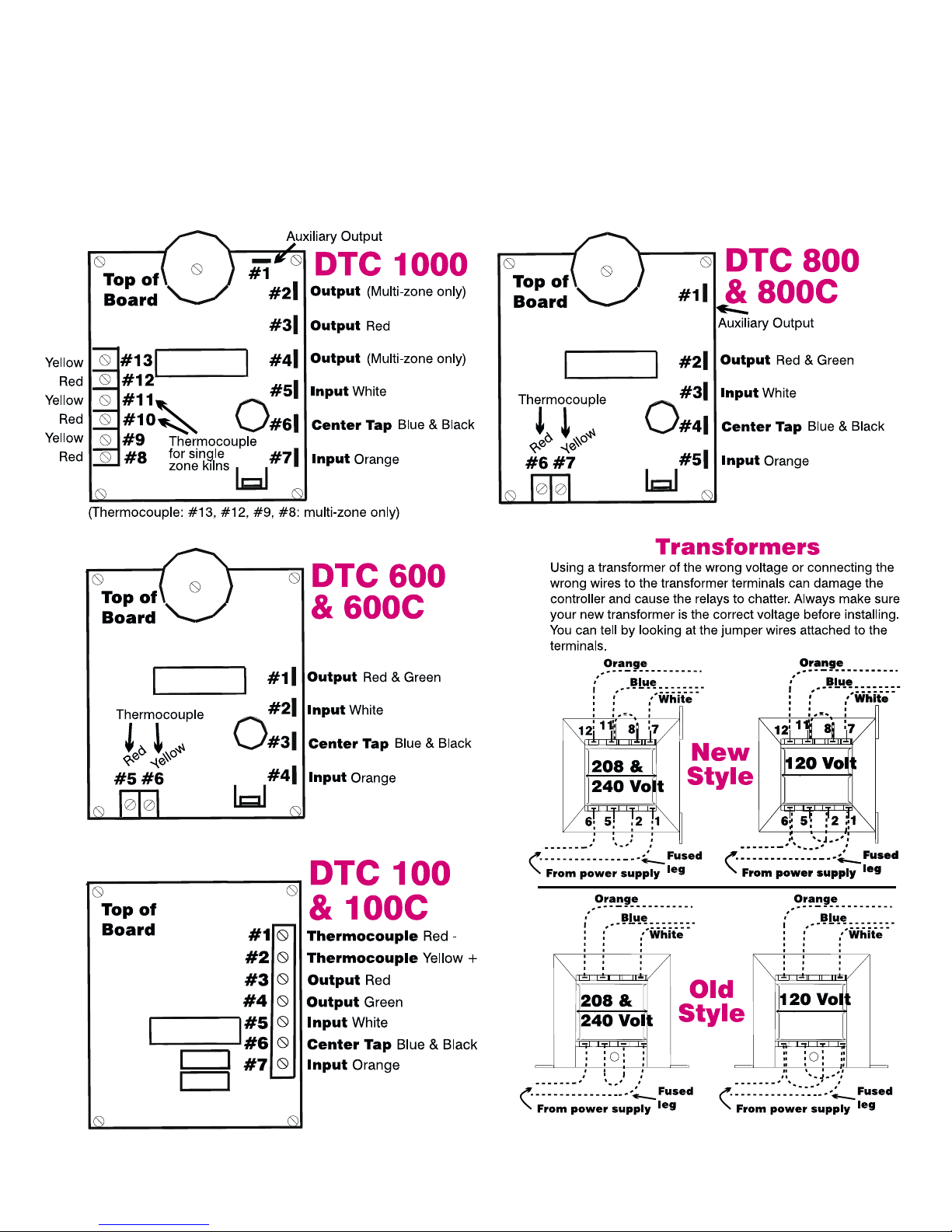
CAUTION: Attaching the INPUT wires (white, orange) to the controller’s OUTPUT
connectors can destroy the controller! Use care when connecting wires.
©Paragon Industries, Inc. IM-195/9-00
1
2011 South Town East Blvd.
Mesquite, Texas 75149-1122
800-876-4328 / 972-288-7557
Toll Free Fax: 888-222-6450
Paragonind@worldnet.att.net
www.paragonweb.com
2
Dear Customer:
Contents
Paragon kilns have proven to be very de
pendable. However, as with all mechanical de
vices, kilns do occasionally need maintenance.
We have packed this guide with information
from the minds of our top engineers and tech
nicians. If you are ever under deadline to get
your kiln running, you will be glad you had this
guide.
If your local dealer does not have a repair
technician, feel free to call the Paragon factory
with questions. But first, try to find the answer
in this trouble shooter. This is usually faster
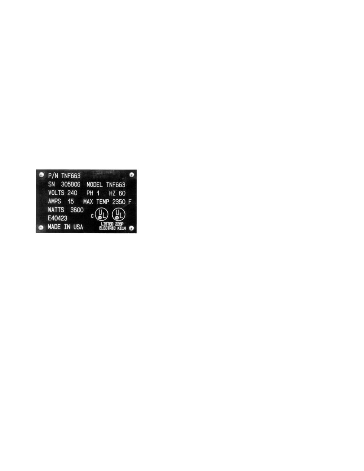
than a phone inquiry. When calling, please have
in front of you the information on your kiln’s
electrical data plate. You will find this on the
side of the kiln switch box.
-
-
Electrical Power Problems
Controller display does NOT turn on. No heat in kiln.. . . . . . . 4
Controller display turns on. No heat in kiln.. . . . . . . . . . . . . . . 5
Kiln fires too slowly or will not reach temperature. . . . . . . . . . 6
-
Some elements do not fire. . . . . . . . . . . . . . . . . . . . . . . . . . . . 8
Kiln heats unevenly. . . . . . . . . . . . . . . . . . . . . . . . . . . . . . . . . . 9
Circuit breaker trips or circuit fuse blows. . . . . . . . . . . . . . . . . 9
Kiln connection box fuse blows. (Heavy amperage kilns.) . . . 9
Kiln switch box ½ amp fuses keep blowing. . . . . . . . . . . . . . 10
Wall outlet gets too hot. . . . . . . . . . . . . . . . . . . . . . . . . . . . . . 10
Temperature Problems
Controller reads wrong temperature.. . . . . . . . . . . . . . . . . . . 10
The kiln overfires. . . . . . . . . . . . . . . . . . . . . . . . . . . . . . . . . . . 11
The display shows erratic temperature readings. . . . . . . . . . 11
The display remains stuck. . . . . . . . . . . . . . . . . . . . . . . . . . . 12
Display digits burn out (parts of display missing). . . . . . . . . 12
Noises
The relay chatters or buzzes. . . . . . . . . . . . . . . . . . . . . . . . . . 12
The controller keeps beeping. . . . . . . . . . . . . . . . . . . . . . . . . 12
Please have all of the information from you kiln’s electrical
data plate in front of you before calling us.
Make a record of all your firings. Include
firing time, temperature, witness cones, and
firing results. These records will be a valuable
trouble-shooting aid. Firing record blanks are
available from Paragon.
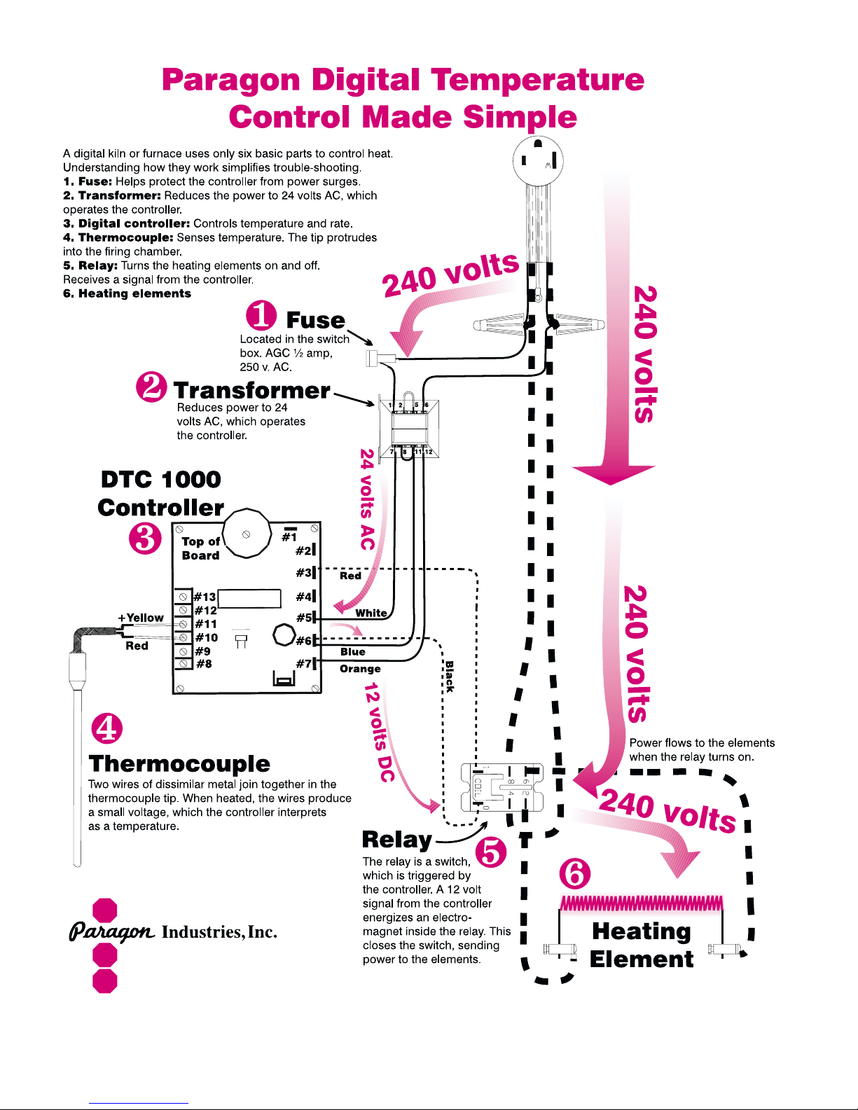
The controller is easy to remove from the
switch box. It is held in place with four screws.
Before removing, please disconnect the power
from the kiln. Certain components on the back
of the controller can be damaged if they touch a
grounded object while the kiln is plugged in.
Please follow the diagrams on page one
carefully when connecting wires to the control
ler. Attaching input wires to output terminals
can damage the controller.
Most of the error messages shown in this
manual do not apply to the DTC 100 series.
Periodically we hold an in-plant kiln main
tenance seminar in Mesquite, Texas. Call for
the next scheduled dates.
-
Error Messages
PF or ErrP during firing. . . . . . . . . . . . . . . . . . . . . . . . . . . . . . 13
FAIL. . . . . . . . . . . . . . . . . . . . . . . . . . . . . . . . . . . . . . . . . . . . . 13
Err 0 . . . . . . . . . . . . . . . . . . . . . . . . . . . . . . . . . . . . . . . . . . . . 13
Err 1 . . . . . . . . . . . . . . . . . . . . . . . . . . . . . . . . . . . . . . . . . . . . 14
Err 2 . . . . . . . . . . . . . . . . . . . . . . . . . . . . . . . . . . . . . . . . . . . . 14
Err 3 . . . . . . . . . . . . . . . . . . . . . . . . . . . . . . . . . . . . . . . . . . . . 15
Err 4 . . . . . . . . . . . . . . . . . . . . . . . . . . . . . . . . . . . . . . . . . . . . 15
Err 6 . . . . . . . . . . . . . . . . . . . . . . . . . . . . . . . . . . . . . . . . . . . . 15
Err 8 . . . . . . . . . . . . . . . . . . . . . . . . . . . . . . . . . . . . . . . . . . . . 15
Err A . . . . . . . . . . . . . . . . . . . . . . . . . . . . . . . . . . . . . . . . . . . . 15
Err B . . . . . . . . . . . . . . . . . . . . . . . . . . . . . . . . . . . . . . . . . . . . 16
Err d . . . . . . . . . . . . . . . . . . . . . . . . . . . . . . . . . . . . . . . . . . . . 16
Err E, Err H, Err t. . . . . . . . . . . . . . . . . . . . . . . . . . . . . . . . . . . 16
Err - . . . . . . . . . . . . . . . . . . . . . . . . . . . . . . . . . . . . . . . . . . . . . 16
Trouble Shooting Tests
-
Wall Receptacle No-Load Test . . . . . . . . . . . . . . . . . . . . . . . . . . . . . . . . 4
Switch Box ½ Amp Fuse Ohmmeter Test. . . . . . . . . . . . . . . . . . . . . . . . 4
Controller Power Input Test. . . . . . . . . . . . . . . . . . . . . . . . . . . . . . . . . . . 4
Element Ohmmeter Test . . . . . . . . . . . . . . . . . . . . . . . . . . . . . . . . . . . . . 5
Controller Power Output Test . . . . . . . . . . . . . . . . . . . . . . . . . . . . . . . . . 6
Door/Lid Switch Test . . . . . . . . . . . . . . . . . . . . . . . . . . . . . . . . . . . . . . . . 6
Receptacle Under Load Test . . . . . . . . . . . . . . . . . . . . . . . . . . . . . . . . . 6
Wall Receptacle Ammeter Test. . . . . . . . . . . . . . . . . . . . . . . . . . . . . . . . 7
Kiln Switch Box High Amperage Fuse Test . . . . . . . . . . . . . . . . . . . . . . 8
Element Glow Test . . . . . . . . . . . . . . . . . . . . . . . . . . . . . . . . . . . . . . . . . 8
Kiln ½ Amp Fuse Power Test . . . . . . . . . . . . . . . . . . . . . . . . . . . . . . . . 10
Relay Coil Test. . . . . . . . . . . . . . . . . . . . . . . . . . . . . . . . . . . . . . . . . . . . 10
Controller Paperclip Test. . . . . . . . . . . . . . . . . . . . . . . . . . . . . . . . . . . . 13
Relay 12 Volt Battery Test . . . . . . . . . . . . . . . . . . . . . . . . . . . . . . . . . . . 14
3
Electrical Power Problems
Controller display does NOT turn on. No heat in kiln.
I
Is the kiln connected to the power?
Make sure the kiln is plugged in. If the kiln’s wall circuit
includes apower disconnectlever, makesure thelever is
in the on position.
I
Has the circuit breaker tripped or fuse
blown?
I
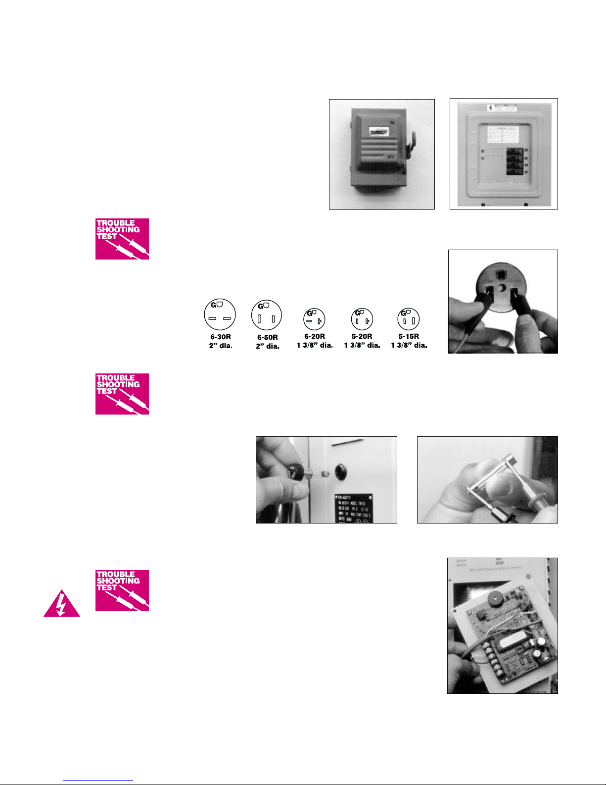
Is power reaching the wall receptacle?
Test with a voltmeter.
Wall Receptacle
No-Load Test
This test should be performed only by an experienced repair person.
Touch only the plastic or rubber handle of the voltmeter probes dur
ing this test. Do not remove the receptacle faceplate.
Follow the instructions that came with your voltmeter, setting it to the AC mode.
Insert the voltmeter
probes in the recepta
cle’s two slotted, hot
connections.
-
Be sure the power disconnect
switch is in the on position.
Know the location of the circuit
breaker panel. Label the breaker that
controls your kiln’s circuit.
-
I
I
Disconnect
Power before
removing
controller and
switch box.
Has the kiln switch box ½ amp fuse blown?
Switch Box ½ Amp Fuse Ohmmeter Test
The kiln’s ½ amp fuse is located in the switch box. Remove by pressing on the fuse holder and turning counter-clockwise half a turn. Check the fuse by placing the
probes of an ohmmeter on the ends of the fuse.If the ohmmeter reads less than an ohm (digital meter) or reads 0 ohms (analog meter), the fuse is okay. If the reading is OPEN (digital meter) or infinity/no needle
movement (analog meter), the fuse is
bad. Replacement fuse:
AGC 1/2 A 250V AC
If replacement kiln fuses keep blow
ing, see “Kiln switch box ½ amp fuses
keep blowing,” page 10.
Is the controller receiving
power? Test INPUTS with
-
Use an ohmmeter to test the switch box fuse.The fuseholder ison the side of most kiln switch
boxes.
Place voltmeter probes in the two
slotted, hot connections of the outlet.
The round connection is the safety
ground.
a voltmeter.
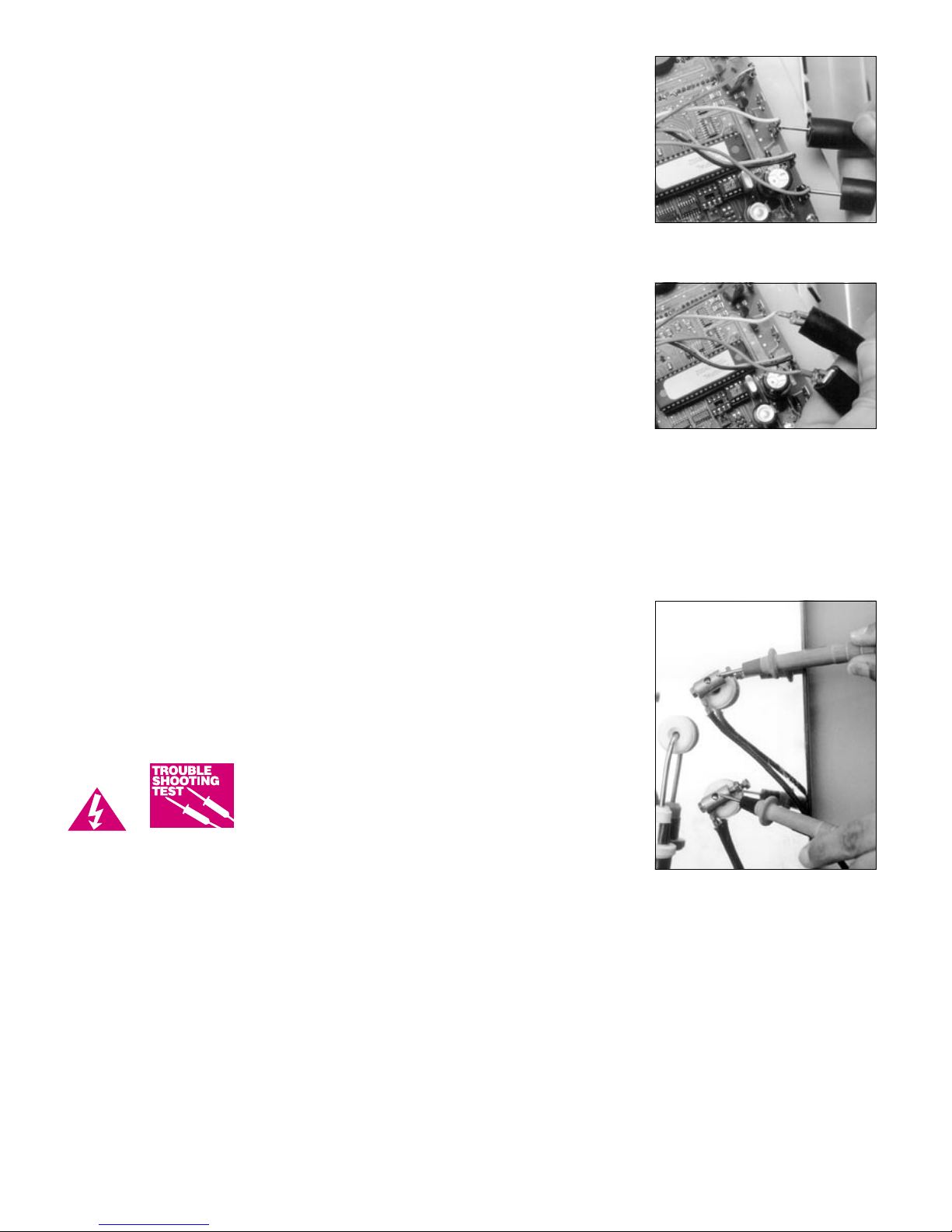
Controller Power Input Test
Make sure the kiln is unplugged, and remove the 4 screws holding the
controller board faceplate to the switch box. Lift faceplate out of box
and letthe boardhang onthe boxwith theback ofthe boardfacing you.
Plug the kiln back in. Touch voltmeter probes (in AC mode) to both INPUT con
nections (the white and orange wires). See diagrams, page 1.
Do not let the back of the boardtouch agrounded object.Make surethe voltmeteris in
the AC mode when placing the probes on INPUT connections.
Controller Input Test Result: the controller is not getting power.
UNPLUG kiln.Check theswitch boxfor disconnectedwires betweenthe cord,trans
former, and controller. If wiring is okay, replace the transformer.
-
-
Disconnect power before removing
the board from the switch box.
4
Controller Input Test Result: the controller is getting 20 - 24 volts
AC.
If you find 20 - 24 volts, correct current is reaching the board from the trans
former. But since the board is not lighting up, it is probably defective. Try
turning off the power to the kiln for ten seconds. The board maylight upwhen
you turnthe power back on. If it does not light up, return the controller forre
pair or replacement.
Controller Input Test Result: the controller is getting less than 20
volts AC.
Did you recently replace the transformer? It may be the wrong voltage. (See
diagrams, page 1.) The voltage is below 20, which is not enough power for the
controller. To find out the cause of low voltage, continue below:
The back of the board is still facing you. Unplug/disconnect the kiln. Remove
the white and orange wires from the board INPUT terminals. Clamp a volt
meter probe to the white wire and the other probe to the orange wire. Use alli
gator clip probes. Do not let the wires touch a grounded object. Plug the kiln
back in.
Result: voltage at disconnected INPUT wires is less than 20: There are
two possiblereasons: 1) Low voltage at thewall receptacle; 2) defective trans
former. If wall receptacle voltage is correct, replace the transformer.
-
-
Testing for voltage at the controller’s INPUT ter
minals.
-
-
Use alligator clips to test for voltage at the dis
-
connected INPUT wires.
-
-
Result: voltage at disconnected INPUT wires is 20 - 24: The transformer is sending correct voltage to the con
troller. Yet when the input wires wereconnected to the controller, voltage was less than 20.This means the control
ler is draining the voltage and is defective. Return the controller for repair or replacement.
CAUTION: Attaching the INPUT wires (white, orange) to the controller’s OUTPUT connectors can destroy the controller! Use care when connecting wires.
Controller display turns on. No heat in kiln.
I
Has a delay been programmed?
The elements will not fire until the delay time has elapsed.
I
Is the relay making its normal clicking sound?
Yes, the relay is clicking.
Test the elements with an ohmmeter:
Element Ohmmeter Test
1 UNPLUG kiln/disconnect the power. Open the kiln’s switch
box. Make sure the wires connecting the relays to the ele
Disconnect
Power before
opening kiln
switch box or
removing the
controller.
ments with an ohmmeter as follows:
2 Touch the ohmmeter leads to the two element connectors of each element.
A no-needle-movement reading on an analog meter, or OPEN on a digital
meter, indicates a broken element.
ments are secure. If connections are okay, check the ele
-
-
-
-
The ohmmetersends an electric current through
the element. If the element is broken, the meter
will show an OPEN circuit.
3 If your elements are wired in parallel, temporarily disconnect the lead wires from one end of the element you are
testing. Holdelement connector with pliersas you remove thescrew. Begentle toavoid breakingthe element.Do
not disturb the screw holding the element, only the one holding the lead wires.
Rule of thumb: ifboth leadwires of an element connect to another element,the elementsare wiredin parallel. Discon
nect the lead wire(s) from one end of the element you are testing.
If the elements check out okay, perform the “Relay 12 Volt Battery Test,” page 14.
No, the relay is not clicking.
We know the controller is receiving voltage, because the display is lit. But the voltage from the transformer may be
too low to power the relays. Perform the “Controller Power Input Test,” page 4. If your controller passes the input
test, perform the “Controller Power Output Test” on the next page:
-
5
 Loading...