

Paradyne TIM1500, TIM1500-12, TIM1500-24 Installation Instructions Manual

TIM1500-12 and TIM1500-24 T1 Inverse Multiplexer
Installation Instructions
Document Number TIM1-A2-GZ40-00
September 2004
Contents
Software and Firmware License Agreement ...................................................... 1
Product Documentation Online .......................................................................... 3
Release Notes ................................................................................................... 3
Unpacking the TIM1500 ..................................................................................... 3
Verifying the TIM1500 Switch Settings .............................................................. 4
Installing the TIM1500 in a BAC ........................................................................ 5
Connecting the T1 Line ...................................................................................... 6
Attaching the RJ21 Connectors ......................................................................... 8
RJ21 Port Pinouts .............................................................................................. 10
Remote Connection ........................................................................................... 11
Verifying the Connection .................................................................................... 11
LED Indicators ................................................................................................... 12
T1 Parameters ................................................................................................... 13
Configuration and Management ........................................................................ 15
Data Storage ...................................................................................................... 15
Regulatory Compliance ..................................................................................... 16
Warranty, Sales, Service, and Training Information ........................................... 17
Software and Firmware License Agreement
ONCE YOU HAVE READ THIS LICENSE AGREEMENT AND AGREE TO ITS
TERMS, YOU MAY USE THE SOFTWARE AND/OR FIRMWARE INCORPORATED
INTO THE PARADYNE PRODUCT. BY USING THE PARADYNE PRODUCT YOU
SHOW YOUR ACCEPTANCE OF THE TERMS OF THIS LICENSE AGREEMENT.
IN THE EVENT THAT YOU DO NOT AGREE WITH ANY OF THE TERMS OF THIS
LICENSE AGREEMENT, PROMPTLY RETURN THE UNUSED PRODUCT IN ITS
ORIGINAL PACKAGING AND YOUR SALES RECEIPT OR INVOICE TO THE
LOCATION WHERE YOU OBTAINED THE PARADYNE PRODUCT OR THE
LOCATION FROM WHICH IT WAS SHIPPED TO YOU, AS APPLICABLE, AND YOU
WILL RECEIVE A REFUND OR CREDIT FOR THE PARADYNE PRODUCT
PURCHASED BY YOU.
TIM1-A2-GZ40-00 September 2004 1

The terms and conditions of this License Agreement (the “Agreement”) will apply
to the software and/or firmware (individually or collectively the “Software”)
incorporated into the Paradyne product (the “Product”) purchased by you and any
derivatives obtained from the Software, including any copy of either. If you have
executed a separate written agreement covering the Software supplied to you
under this purchase, such separate written agreement shall govern.
Paradyne Corporation (“Paradyne”) grants to you, and you (“Licensee”) agree to
accept a personal, non-transferable, non-exclusive, right (without the right to
sublicense) to use the Software, solely as it is intended and solely as incorporated
in the Product purchased from Paradyne or its authorized distributor or reseller
under the following terms and conditions:
1. Ownership: The Software is the sole property of Paradyne and/or its licensors.
The Licensee acquires no title, right or interest in the Software other than the
license granted under this Agreement.
2. Licensee shall not use the Software in any country other than the country in
which the Product was rightfully purchased except upon prior written notice to
Paradyne and an agreement in writing to additional terms.
3. The Licensee shall not reverse engineer, decompile or disassemble the
Software in whole or in part.
4. The Licensee shall not copy the Software except for a single archival copy.
5. Except for the Product warranty contained in the manual, the Software is
provided “AS IS” and in its present state and condition and Paradyne makes
no other warranty whatsoever with respect to the Product purchased by you.
THIS AGREEMENT EXPRESSLY EXCLUDES ALL OTHER WARRANTIES,
WHETHER EXPRESS OR IMPLIED, OR ORAL OR WRITTEN, INCLUDING
WITHOUT LIMITATION:
a. Any warranty that the Software is error-free, will operate uninterrupted in
your operating environment, or is compatible with any equipment or
software configurations; and
b. ANY AND ALL IMPLIED WARRANTIES, INCLUDING WITHOUT
LIMITATION IMPLIED WARRANTIES OF MERCHANTABILITY,
FITNESS FOR A PARTICULAR PURPOSE AND NON-INFRINGEMENT.
Some states or other jurisdictions do not allow the exclusion of implied
warranties on limitations on how long an implied warranty lasts, so the above
limitations may not apply to you. This warranty gives you specific legal rights,
and you may also have other rights which vary from one state or jurisdiction to
another.
6. In no event will Paradyne be liable to Licensee for any consequential,
incidental, punitive or special damages, including any lost profits or lost
savings, loss of business information or business interruption or other
pecuniary loss arising out of the use or inability to use the Software, whether
based on contract, tort, warranty or other legal or equitable grounds, even if
Paradyne has been advised of the possibility of such damages, or for any
claim by any third party.
7. The rights granted under this Agreement may not be assigned, sublicensed or
otherwise transferred by the Licensee to any third party without the prior
written consent of Paradyne.
2 September 2004 TIM1-A2-GZ40-00

8. This Agreement and the license granted under this Agreement shall be
terminated in the event of breach by the Licensee of any provisions of this
Agreement.
9. Upon such termination, the Licensee shall refrain from any further use of the
Software and destroy the original and all copies of the Software in the
possession of Licensee together with all documentation and related materials.
10. This Agreement shall be governed by the laws of the State of Florida, without
regard to its provisions concerning conflicts of laws.
Product Documentation Online
Complete documentation for Paradyne products is available at
www.paradyne.com. Select Support → Technical Manuals.
To order a paper copy of a Paradyne document, or to speak with a sales
representative, please call 1-727-530-2000.
Release Notes
Release notes for this product are available in the subscriber firmware area of
www.paradyne.com. Select Support → Subscriber Firmware.
Always review the relevant release notes before installing a new card.
Unpacking the TIM1500
HANDLING PRECAUTIONS FOR
!
STATIC-SENSITIVE DEVICES
This product is designed to protect sensitive components from damage
due to electrostatic discharge (ESD) during normal operation. When
performing installation procedures, however, take proper static control
precautions to prevent damage to equipment. If you are not sure of the
proper static control precautions, contact your nearest sales or service
representative.
Unpack and inspect the TIM1500. If there is visible damage, do not attempt to
connect the device; contact your sales or service representative.
TIM1-A2-GZ40-00 September 2004 3
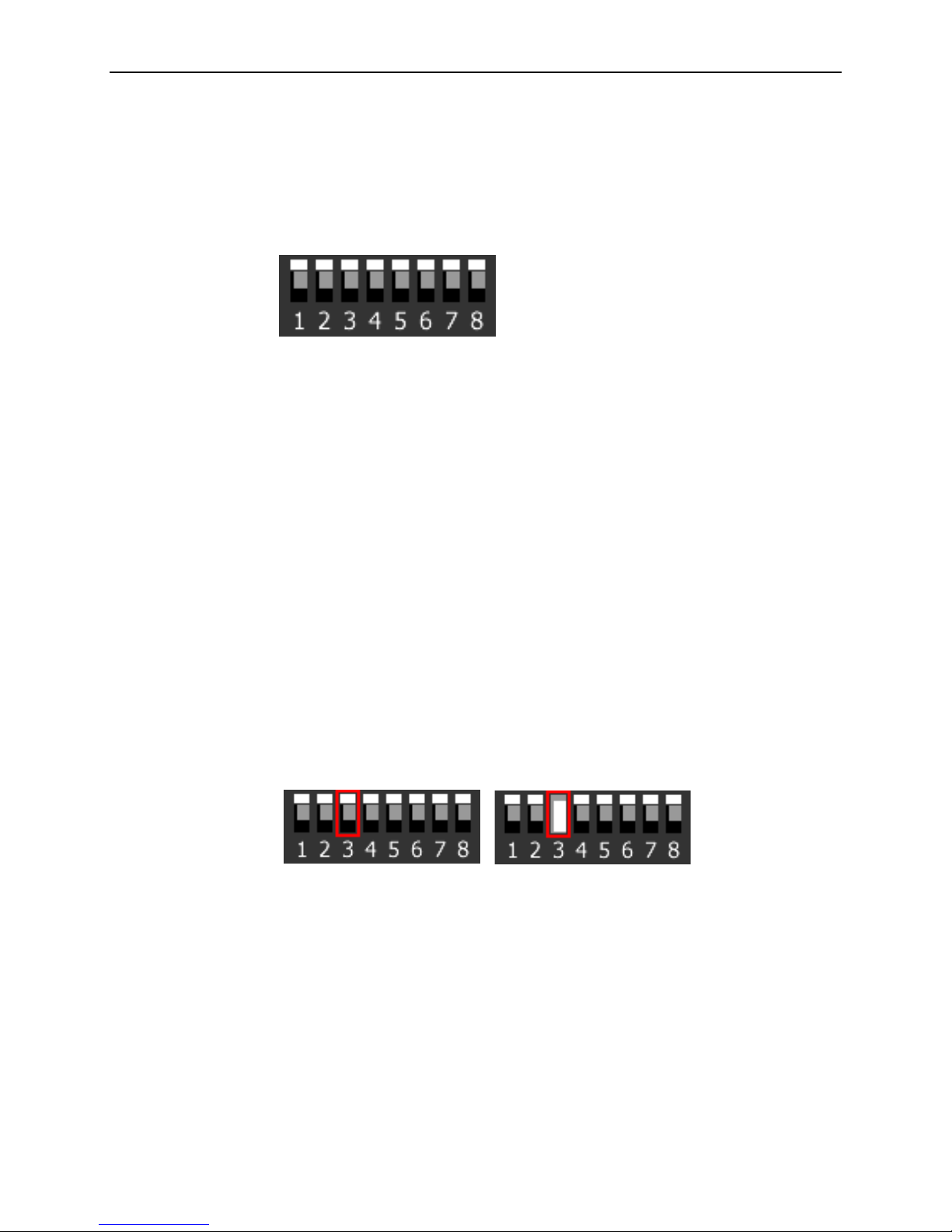
Verifying the TIM1500 Switch Settings
The TIM1500 has a bank of eight switches at the rear of the module (opposite the
faceplate). Switches are numbered from left to right, 1–8. All eight switches should
be in the default up (ON) position. Switches 1 and 4–8 are not used.
NOTE: TIM1500s with printed circuit boards (PCBs) at revision level 810-0000AA
have eight switch banks. For PCBs with eight switch banks, the following sections
(Switch 2 and Switch 3) refer to switches in the switch bank labeled SW 7. All
switches on the other seven switch banks should be in the default up (ON)
position. PCBs at any revision level other than 810-0000AA have only one switch
bank.
Switch 2
CAUTION: Switch 2 indicates to the Multiplexer Uplink Module (MUM) in the same
chassis that the module is a T1 inverse multiplexer. The switch must be in the up
(ON) position. The TIM1500 will not link up if Switch 2 is in the down position.
Switch 3
Switch 3 indicates to the MUM whether the TIM1500 will be acting as a T1
provider or a T1 subscriber. The default up (ON) position specifies that the
TIM1500 acts as a provider. In most cases, this is the desired setting. The
TIM1500 can, however, be configured to act as a T1 subscriber, if so desired, by
placing Switch 3 in the down (Off) position.
Provider Mode Subscriber Mode
NOTE: You cannot set speed or timing configurations on a TIM1500 in subscriber
mode. These settings will be determined via each port's communication with its
respective partner T1 provider.
4 September 2004 TIM1-A2-GZ40-00

Installing the TIM1500 in a BAC
There must be a Multiplexer Uplink Module (MUM) installed in the Broadband
Access Concentrator (BAC) in order for interface modules to operate.
The 12000 and 12000E BACs are fourteen slot chassis. Slots 1–12 are
reserved for interface modules (such as the AIM24000), and the remaining
slots (13 and 14 in the 12000 and U1 and U2 in the 12000E) are reserved for
management modules.
The 4000 BAC is a five slot chassis; slots 1–4 are reserved for interface
modules and slot 5 is reserved for a MUM.
Interface modules are hot swappable. Installing or removing an interface module
while the chassis is powered up does not affect the operational status of other
interface modules within the chassis.
Procedure
1. Align the TIM1500 with the slot module guides of the chosen slot for
installation (slot 1–12 in the 12000 and 12000E or slot 1–4 in the 4000 and
4000E).
2. Slide the TIM1500 firmly into the chassis. Do not use excessive force.
3. Secure the TIM1500 by tightening the fastening screws on the module
faceplate.
4. Verify that the PWR (Power) LED on the TIM1500 faceplate is illuminated. If
your BAC is not yet powered up, refer to the installation instructions for your
BAC.
TIM1-A2-GZ40-00 September 2004 5
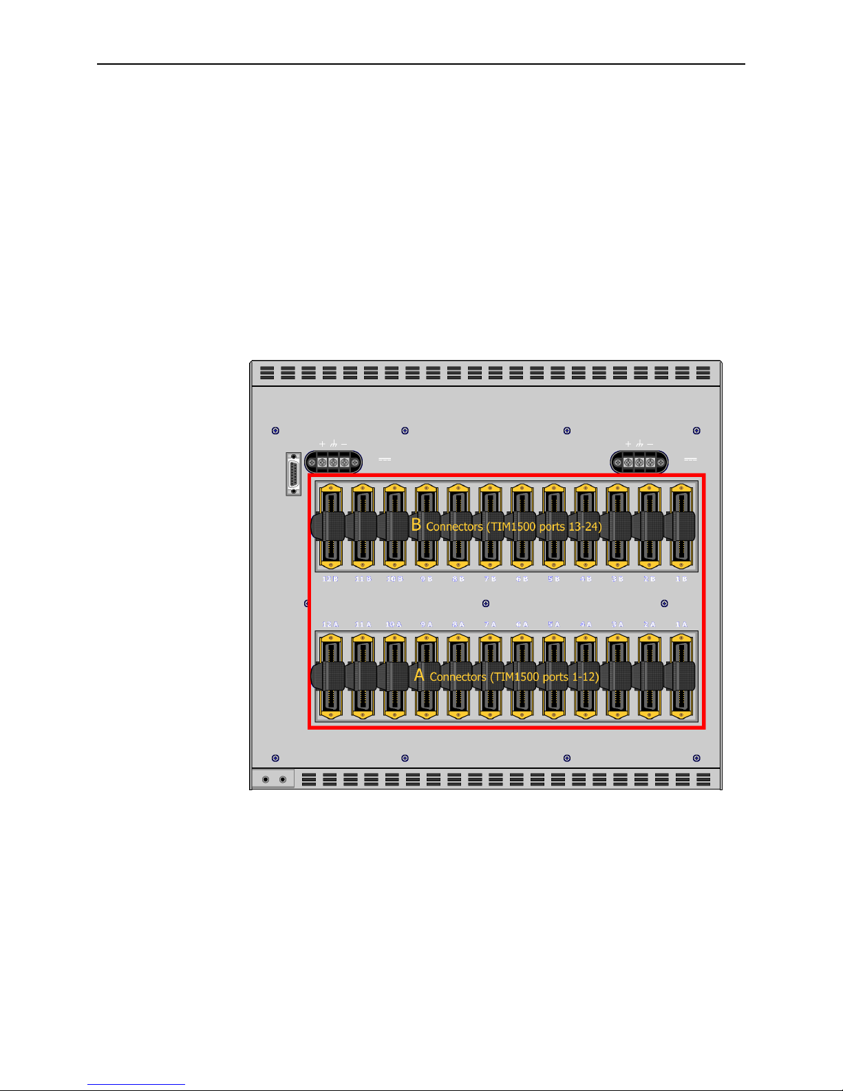
Connecting the T1 Line
T1 cables must be connected according to the BAC slot in which the TIM1500 was
installed. For example, a TIM15000 installed in Slot 3 of an 12000E uses the RJ21
connectors labeled 3A and 3B.
12000E and 4000E
Each interface module slot on the 12000E and 4000E has two corresponding
RJ21 connectors located on the back of the chassis. On the 12000E, the bottom
row of RJ21 connectors (A) provides the T1 connection for TIM1500 ports 1–12,
and the top row of RJ21 connectors (B) provides the T1 connection for TIM1500
ports 13–24.
On the 4000E, the A connectors for each interface module slot are on the left and
the B connectors are on the right.
6 September 2004 TIM1-A2-GZ40-00
 Loading...