

Page 1

MODEL 916x/926x
T1 ACCESS MUX
TECHNICAL REFERENCE
Document No. 9161-A2-GH30-31
July 1998
Page 2

Copyright 1998 Paradyne Corporation.
All rights reserved.
Printed in U.S.A.
Notice
This publication is protected by federal copyright law. No part of this publication may be copied or distributed,
transmitted, transcribed, stored in a retrieval system, or translated into any human or computer language in any form
or by any means, electronic, mechanical, magnetic, manual or otherwise, or disclosed to third parties without the
express written permission of Paradyne Corporation, 8545 126th Avenue North, P.O. Box 2826, Largo,
Florida 33779-2826.
Paradyne Corporation makes no representation or warranties with respect to the contents hereof and specifically
disclaims any implied warranties of merchantability or fitness for a particular purpose. Further, Paradyne Corporation
reserves the right to revise this publication and to make changes from time to time in the contents hereof without
obligation of Paradyne Corporation to notify any person of such revision or changes.
Changes and enhancements to the product and to the information herein will be documented and issued as a new
release to this manual.
Warranty, Sales, and Service Information
Contact your local sales representative, service representative, or distributor directly for any help needed. For
additional information concerning warranty , sales, service, repair , installation, documentation, training, distributor
locations, or Paradyne worldwide office locations, use one of the following methods:
Via the Internet: Visit the Paradyne World Wide W eb site at http://www.paradyne.com
Via Telephone: Call our automated call system to receive current information via fax or to speak with a
company representative.
— Within the U.S.A., call 1-800-870-2221
— Outside the U.S.A., call 1-727-530-2340
Trademarks
All products and services mentioned herein are the trademarks, service marks, registered trademarks or registered
service marks of their respective owners.
Printed on recycled paper
A
July 1998
9161-A2-GH30-31
Page 3

Important Regulatory Information
EMI Warnings
!
WARNING:
This equipment has been tested and found to comply with the limits for a Class A digital device,
pursuant to Part 15 of the FCC rules. These limits are designed to provide reasonable protection against
harmful interference when the equipment is operated in a commercial environment. This equipment
generates, uses, and can radiate radio frequency energy and, if not installed and used in accordance
with the instruction manual, may cause harmful interference to radio communications. Operation of this
equipment in a residential area is likely to cause harmful interference in which case the user will be
required to correct the interference at his own expense.
The authority to operate this equipment is conditioned by the requirements that no modifications will be
made to the equipment unless the changes or modifications are expressly approved by Paradyne.
!
WARNING:
To Users of Digital Apparatus in Canada:
This Class A digital apparatus meets all requirements of the Canadian interference-causing equipment
regulations.
Cet appareil numérique de la classe A respecte toutes les exigences du règlement sur le matériel
brouilleur du Canada.
9161-A2-GH30-31 July 1998
B
Page 4

Important Regulatory Information
Important Safety Instructions
1. Read and follow all warning notices and instructions marked on the product or included in the manual.
2. All installation and service must be performed by qualified service personnel, as opening or removing covers may
expose dangerous voltage points or other risks.
3. This product is intended to be used with a 3-wire grounding type plug – a plug which has a grounding pin. This is
a safety feature. Equipment grounding is vital to ensure safe operation. Do not defeat the purpose of the
grounding type plug by modifying the plug or using an adapter.
Prior to installation, use an outlet tester or a voltmeter to check the ac receptacle for the presence of earth
ground. If the receptacle is not properly grounded, the installation must not continue until a qualified electrician
has corrected the problem.
If a 3-wire grounding type power source is not available, consult a qualified electrician to determine another
method of grounding the equipment.
The rear I/O panel has provision for a permanently connected protective earthing (grounding) conductor. Connect
a 6-14 AWG conductor to this solderless lug connector, identified by the protective earth symbol.
4. Slots and openings in the cabinet are provided for ventilation. To ensure reliable operation of the product and to
protect it from overheating, these slots and openings must not be blocked or covered. Always install the housings
in a vertical, upright position to allow for proper cooling.
5. Do not allow anything to rest on the power cord and do not locate the product where persons will walk on the
power cord.
6. General purpose cables are provided with this product. Special cables, which may be required by the regulatory
inspection authority for the installation site, are the responsibility of the customer. Use a minimum 26 AWG line
cord for network connections.
7. When installed in the final configuration, the product must comply with the applicable Safety Standards and
regulatory requirements of the country in which it is installed. If necessary , consult with the appropriate regulatory
agencies and inspection authorities to ensure compliance.
8. A rare phenomenon can create a voltage potential between the earth grounds of two or more buildings. If
products installed in separate buildings are interconnected, the voltage potential may cause a hazardous
condition. Consult a qualified electrical consultant to determine whether or not this phenomenon exists and, if
necessary, implement corrective action prior to interconnecting the products.
must
9. Filler panels are provided with the housings to cover unused slots. You
slots to avoid possible injury from electrical shock and to maintain compliance with FCC rules.
10. In addition, if the equipment is to be used with telecommunications circuits, take the following precautions:
install filler panels on the unused
— Never install telephone wiring during a lightning storm.
— Never install telephone jacks in wet locations unless the jack is specifically designed for wet locations.
— Never touch uninsulated telephone wires or terminals unless the telephone line has been disconnected at the
network interface.
— Use caution when installing or modifying telephone lines.
— Avoid using a telephone (other than a cordless type) during an electrical storm. There may be a remote risk of
electric shock from lightning.
— Do not use the telephone to report a gas leak in the vicinity of the leak.
C
July 1998
9161-A2-GH30-31
Page 5

Important Regulatory Information
Government Requirements
Certain governments require that instructions pertaining to connection to the telephone network be included in the
installation and operation manual. Specific instructions are listed in the following sections.
United States
Notice to Users of the Telephone Network
This equipment complies with Part 68 of the FCC rules. On the equipment is a label or silk screened text that
contains, among other information, the FCC registration number for this equipment. If requested, please provide this
information to your telephone company .
If your T1 equipment causes harm to the telephone network, the telephone company may discontinue your service
temporarily. If possible, they will notify you in advance. But if advance notice is not practical, you will be notified as
soon as possible. You will be advised of your right to file a complaint with the FCC.
Your telephone company may make changes in facilities, equipment, operations, or procedures that could affect the
proper operation of your equipment. If so, you will be given advance notice so as to give you an opportunity to
maintain uninterrupted service.
No repairs may be performed by the user. Should you experience dif ficulty with this equipment, refer to the
Sales and Service Information
Make the T1 network connection using a Universal Service Order Code (USOC) type RJ48C jack for single-line
installations and type RJ48H jack for multiline installations. Specify both the Service Order Code 6.0N, as well as the
proper Facility Interface Code, to the telephone company when ordering the T1 line. The T1 equipment can be
configured to support any of the framing format and line signaling techniques shown in the table below. The T1
equipment’s configuration must correspond to the T1 line’s parameters.
section on page A.
Warranty,
Facility Interface Codes
Code
04DU9-BN 1.544 Mbps superframe format (SF) without line power
04DU9-DN 1.544 Mbps SF and B8ZS without line power
04DU9-1KN 1.544 Mbps ANSI ESF without line power
04DU-1SN 1.544 Mbps ANSI ESF and B8ZS without line power
The Federal Communication’s Commission (FCC) requires that the end user (person responsible for operation and
maintenance of the equipment) file an affidavit with the local exchange carrier when connecting unprotected
Customer Premises Equipment (CPE) to the public T1 network. The T1 equipment is considered an unprotected CPE
because the analog through transmission gain paths, associated with the voice cards, are user adjustable. This
affidavit is required whenever digital terminal equipment without encoded analog content and billing protection is used
to transmit digital signals containing encoded analog content which is intended for eventual conversion into
voice-band analog signals and retransmitted on the network. This affidavit shall affirm that either no encoded analog
content or billing information is being transmitted or that the output of the device meets Part 68 encoded analog
content or billing protection specifications. An affidavit form has been provided for your convenience.
Description
9161-A2-GH30-31 July 1998
D
Page 6

Important Regulatory Information
!
WARNING:
In order to maintain compliance with Part 68, FCC Rules and Industry Canada’s CS-03 Specification, the
transmit gain settings associated with the E&M, FXO and FXS V oice APMs must be set to ensure that:
— The absolute signal power of the encoded analog signals, other than live voice and network control
signaling, will not exceed –12 dBm when averaged over any 3-second interval.
— For network control signals (such as DTMF), the level will not exceed –3 dBm.
The E&M, FXO and FXS voice lines are to be connected to locally attached equipment only . Under no
circumstances should voice lines be used on exposed (outside) plant lines.
After the telephone company has installed the requested service and jack, you can connect the equipment to the
network. An FCC-compliant telephone cord and modular plug are provided with this equipment. This equipment is
designed to be connected to the telephone network or premises wiring using a compatible modular jack that is Part 68
compliant.
Canada
Notice to Users of the Canadian Telephone Network
The Industry Canada label identifies certified equipment. This certification means that the equipment meets
telecommunications network protective, operational and safety requirements as prescribed in the appropriate Terminal
Equipment Technical Requirements document(s). The Department does not guarantee the equipment will operate to
the user’s satisfaction.
Before installing this equipment, users should ensure that it is permissible to be connected to the facilities of the local
telecommunications company. The equipment must also be installed using an acceptable method of connection. The
customer should be aware that compliance with the above conditions may not prevent degradation of service in some
situations.
Repairs to certified equipment should be coordinated by a representative designated by the supplier. Any repairs or
alterations made by the user to this equipment, or equipment malfunctions, may give the telecommunications
company cause to request to disconnect the equipment.
Users should ensure for their own protection that the electrical ground connections of the power utility , telephone lines
and internal metallic water pipe system, if present, are connected together. This precaution may be particularly
important in rural areas.
CAUTION:
Users should not attempt to make such connections themselves, but should contact the appropriate
electric inspection authority , or electrician, as appropriate.
The Ringer Equivalence Number (REN) assigned to each terminal device provides an indication of the maximum
number of terminals allowed to be connected to a telephone interface. The termination on an interface may consist of
any combination of devices subject only to the requirement that the sum of the Ringer Equivalence Numbers of all the
devices does not exceed 5.
If your equipment is in need of repair, refer to the procedures described in the
Information
section on page A.
Warranty, Sales and Service
E
July 1998
9161-A2-GH30-31
Page 7

Contents
About This Guide
Document Purpose and Intended Audience ix. . . . . . . . . . . . . . . . . . . . . . . . .
Document Summary ix. . . . . . . . . . . . . . . . . . . . . . . . . . . . . . . . . . . . . . . . . . . . .
Conventions Used x. . . . . . . . . . . . . . . . . . . . . . . . . . . . . . . . . . . . . . . . . . . . . .
Product-Related Documents xi. . . . . . . . . . . . . . . . . . . . . . . . . . . . . . . . . . . . . .
Reference Documents xii. . . . . . . . . . . . . . . . . . . . . . . . . . . . . . . . . . . . . . . . . . .
1 About the T1 Access Mux
Overview 1-1. . . . . . . . . . . . . . . . . . . . . . . . . . . . . . . . . . . . . . . . . . . . . . . . . . . . . .
Components 1-2. . . . . . . . . . . . . . . . . . . . . . . . . . . . . . . . . . . . . . . . . . . . . . . .
Features 1-6. . . . . . . . . . . . . . . . . . . . . . . . . . . . . . . . . . . . . . . . . . . . . . . . . . . . . . .
2 Management and Control
Overview 2-1. . . . . . . . . . . . . . . . . . . . . . . . . . . . . . . . . . . . . . . . . . . . . . . . . . . . . .
Configuring Local Management Control 2-1. . . . . . . . . . . . . . . . . . . . . . . . . . . .
Configuring End-to-End Management Control 2-4. . . . . . . . . . . . . . . . . . . . . . .
3 Applications
Overview 3-1. . . . . . . . . . . . . . . . . . . . . . . . . . . . . . . . . . . . . . . . . . . . . . . . . . . . . .
T1 Access Unit with High Speed Data 3-2. . . . . . . . . . . . . . . . . . . . . . . . . . . . .
T1 Access Unit with High Speed Data and E&M 3-3. . . . . . . . . . . . . . . . . . . . .
T1 Access Unit with High Speed Data and APL 3-4. . . . . . . . . . . . . . . . . . . . .
T1 Access Unit with High Speed Data, FXS and E&M 3-5. . . . . . . . . . . . . . . .
T1 Access Unit with High Speed Data and Drop & Insert 3-6. . . . . . . . . . . . .
Channel Bank Replacement and Additions 3-7. . . . . . . . . . . . . . . . . . . . . . . . .
Off-Premises Extension (OPX) 3-8. . . . . . . . . . . . . . . . . . . . . . . . . . . . . . . . . . . .
Direct Inward Dial (DID) 3-8. . . . . . . . . . . . . . . . . . . . . . . . . . . . . . . . . . . . . . . . . .
Video Conferencing 3-9. . . . . . . . . . . . . . . . . . . . . . . . . . . . . . . . . . . . . . . . . . . . .
Consolidated T1 Access of DDS Circuits 3-10. . . . . . . . . . . . . . . . . . . . . . . . . . .
Creating a Management Link Through the COM Port 2-2. . . . . . . . . . . . .
Configuring an External Device (Connected to the COM Port) 2-3. . . . .
Management Control Using the ESF FDL 2-4. . . . . . . . . . . . . . . . . . . . . . .
Management Control Using an EDL 2-5. . . . . . . . . . . . . . . . . . . . . . . . . . . .
9161-A2-GH30-30
April 1998
i
Page 8

Contents
4 User Interface
Introduction 4-1. . . . . . . . . . . . . . . . . . . . . . . . . . . . . . . . . . . . . . . . . . . . . . . . . . . .
Async Terminal User Interface Access 4-1. . . . . . . . . . . . . . . . . . . . . . . . . . . . .
Network Management 4-1. . . . . . . . . . . . . . . . . . . . . . . . . . . . . . . . . . . . . . . . . . .
Menu Hierarchy 4-1. . . . . . . . . . . . . . . . . . . . . . . . . . . . . . . . . . . . . . . . . . . . . . . . .
Screen Field Types 4-2. . . . . . . . . . . . . . . . . . . . . . . . . . . . . . . . . . . . . . . . . . . . . .
Navigating the Screens 4-5. . . . . . . . . . . . . . . . . . . . . . . . . . . . . . . . . . . . . . . . . .
Main Menu Screen 4-2. . . . . . . . . . . . . . . . . . . . . . . . . . . . . . . . . . . . . . . . . .
What Affects Screen Displays 4-3. . . . . . . . . . . . . . . . . . . . . . . . . . . . . . . . .
Screen Work Areas 4-3. . . . . . . . . . . . . . . . . . . . . . . . . . . . . . . . . . . . . . . . . .
Keyboard Keys 4-5. . . . . . . . . . . . . . . . . . . . . . . . . . . . . . . . . . . . . . . . . . . . . .
Screen Function Keys 4-6. . . . . . . . . . . . . . . . . . . . . . . . . . . . . . . . . . . . . . . .
Selecting from a Menu 4-7. . . . . . . . . . . . . . . . . . . . . . . . . . . . . . . . . . . . . . .
Selecting a Field 4-7. . . . . . . . . . . . . . . . . . . . . . . . . . . . . . . . . . . . . . . . . . . .
Making Input Selections 4-7. . . . . . . . . . . . . . . . . . . . . . . . . . . . . . . . . . . . . .
Switching Between Screen Work Areas 4-8. . . . . . . . . . . . . . . . . . . . . . . .
Accessing the User Interface 4-8. . . . . . . . . . . . . . . . . . . . . . . . . . . . . . . . . .
5 Setting Up
Considerations When Setting Up 5-1. . . . . . . . . . . . . . . . . . . . . . . . . . . . . . . . . .
Selecting a Management Interface 5-2. . . . . . . . . . . . . . . . . . . . . . . . . . . . .
Logins 5-2. . . . . . . . . . . . . . . . . . . . . . . . . . . . . . . . . . . . . . . . . . . . . . . . . . . . . . . . .
Adding System Identity Information 5-3. . . . . . . . . . . . . . . . . . . . . . . . . . . . . . . .
Setting Date and Time 5-4. . . . . . . . . . . . . . . . . . . . . . . . . . . . . . . . . . . . . . . . . . .
Configuring the T1 Access Unit 5-4. . . . . . . . . . . . . . . . . . . . . . . . . . . . . . . . . . .
Recommended Order of Configuration 5-5. . . . . . . . . . . . . . . . . . . . . . . . .
Configuration Option Areas 5-5. . . . . . . . . . . . . . . . . . . . . . . . . . . . . . . . . . .
Accessing and Displaying Configuration Options 5-5. . . . . . . . . . . . . . . .
Changing Configuration Options 5-6. . . . . . . . . . . . . . . . . . . . . . . . . . . . . . .
Saving Configuration Options 5-6. . . . . . . . . . . . . . . . . . . . . . . . . . . . . . . . .
Configuring T1 and DSX-1 Interfaces 5-7. . . . . . . . . . . . . . . . . . . . . . . . . . . . . .
Configuring the Network Interface 5-7. . . . . . . . . . . . . . . . . . . . . . . . . . . . .
Configuring the DSX-1 Interface 5-14. . . . . . . . . . . . . . . . . . . . . . . . . . . . . . .
Configuring Ports 5-16. . . . . . . . . . . . . . . . . . . . . . . . . . . . . . . . . . . . . . . . . . . . . . .
Configuring Sync Data Ports 5-16. . . . . . . . . . . . . . . . . . . . . . . . . . . . . . . . . .
Configuring Voice Ports 5-24. . . . . . . . . . . . . . . . . . . . . . . . . . . . . . . . . . . . . .
Configuring OCU-DP Ports 5-32. . . . . . . . . . . . . . . . . . . . . . . . . . . . . . . . . . .
Copying Port Configurations 5-35. . . . . . . . . . . . . . . . . . . . . . . . . . . . . . . . . .
ii
April 1998
9161-A2-GH30-30
Page 9

Contents
Assigning Cross Connections 5-36. . . . . . . . . . . . . . . . . . . . . . . . . . . . . . . . . . . . .
Assigning DSX-1 Timeslots to the Network Interface 5-39. . . . . . . . . . . . .
DSX-1 Signaling Assignments and Trunk Conditioning 5-40. . . . . . . . . . .
Assigning Network 2 Timeslots to Network 1 Interface Timeslots 5-43. . .
Network to Network Signaling Assignments and Trunk
Conditioning 5-43. . . . . . . . . . . . . . . . . . . . . . . . . . . . . . . . . . . . . . . . . . . . . . . .
Assigning Voice Ports to DSX-1 or Network Interface Timeslots 5-44. . . .
Assigning Sync Data Ports 5-44. . . . . . . . . . . . . . . . . . . . . . . . . . . . . . . . . . . .
Assigning OCU-DP Data Ports 5-46. . . . . . . . . . . . . . . . . . . . . . . . . . . . . . . .
Clearing Port Assignments 5-47. . . . . . . . . . . . . . . . . . . . . . . . . . . . . . . . . . . .
Setting System Options 5-48. . . . . . . . . . . . . . . . . . . . . . . . . . . . . . . . . . . . . . . . . .
Setting User Interface Options 5-52. . . . . . . . . . . . . . . . . . . . . . . . . . . . . . . . . . . .
Setting Up the Communication Port 5-52. . . . . . . . . . . . . . . . . . . . . . . . . . . .
Setting Up the Communication Port to Support an External
Device 5-57. . . . . . . . . . . . . . . . . . . . . . . . . . . . . . . . . . . . . . . . . . . . . . . . . . . . .
Setting Up to Support a Telnet or FTP Session 5-61. . . . . . . . . . . . . . . . . .
Configuring for Alarms and Traps 5-64. . . . . . . . . . . . . . . . . . . . . . . . . . . . . . . . .
Setting Management and Communication Options 5-67. . . . . . . . . . . . . . . . . .
Setting Communication Protocol 5-67. . . . . . . . . . . . . . . . . . . . . . . . . . . . . . .
Setting Up for SNMP Management 5-70. . . . . . . . . . . . . . . . . . . . . . . . . . . .
Setting Up SNMP NMS Security 5-72. . . . . . . . . . . . . . . . . . . . . . . . . . . . . . .
Setting Up for SNMP Traps 5-74. . . . . . . . . . . . . . . . . . . . . . . . . . . . . . . . . . .
Setting Up and Placing a Call 5-78. . . . . . . . . . . . . . . . . . . . . . . . . . . . . . . . . . . . .
6 Security
Limiting Access 6-1. . . . . . . . . . . . . . . . . . . . . . . . . . . . . . . . . . . . . . . . . . . . . . . . .
Limiting Async Terminal Direct Access 6-1. . . . . . . . . . . . . . . . . . . . . . . . . .
Limiting Telnet Access 6-3. . . . . . . . . . . . . . . . . . . . . . . . . . . . . . . . . . . . . . .
Controlling External Device Access 6-4. . . . . . . . . . . . . . . . . . . . . . . . . . . .
Controlling SNMP Access 6-5. . . . . . . . . . . . . . . . . . . . . . . . . . . . . . . . . . . . . . . .
Disabling SNMP Access 6-5. . . . . . . . . . . . . . . . . . . . . . . . . . . . . . . . . . . . . .
Assigning SNMP Community Names and Access Levels 6-6. . . . . . . . .
Limiting SNMP Access Through IP Addresses 6-7. . . . . . . . . . . . . . . . . .
Creating a Login 6-8. . . . . . . . . . . . . . . . . . . . . . . . . . . . . . . . . . . . . . . . . . . . . . . .
Deleting a Login 6-9. . . . . . . . . . . . . . . . . . . . . . . . . . . . . . . . . . . . . . . . . . . . . . . .
9161-A2-GH30-30
April 1998
iii
Page 10

Contents
7 Displaying System Information
Displaying System and NAM Identity Information 7-1. . . . . . . . . . . . . . . . . . . .
Displaying APM Identity Information 7-2. . . . . . . . . . . . . . . . . . . . . . . . . . . . . . .
Displaying System and Test Status 7-2. . . . . . . . . . . . . . . . . . . . . . . . . . . . . . . .
Displaying Voice APM Status 7-3. . . . . . . . . . . . . . . . . . . . . . . . . . . . . . . . . . . . .
Displaying Cross Connect Status 7-7. . . . . . . . . . . . . . . . . . . . . . . . . . . . . . . . . .
Displaying Network Channels 7-7. . . . . . . . . . . . . . . . . . . . . . . . . . . . . . . . .
Displaying DSX-1 Channels 7-9. . . . . . . . . . . . . . . . . . . . . . . . . . . . . . . . . . .
Displaying Port Assignments 7-11. . . . . . . . . . . . . . . . . . . . . . . . . . . . . . . . . .
Displaying Device Name and SNMP System
Identification Information 7-12. . . . . . . . . . . . . . . . . . . . . . . . . . . . . . . . . . . . .
Viewing Network and Sync Data Performance Statistics 7-12. . . . . . . . . . . . . .
What Statistics Can Be Collected? 7-12. . . . . . . . . . . . . . . . . . . . . . . . . . . . .
Network Performance Statistics 7-13. . . . . . . . . . . . . . . . . . . . . . . . . . . . . . .
Sync Data Performance Statistics 7-13. . . . . . . . . . . . . . . . . . . . . . . . . . . . .
Displaying Performance Statistics 7-14. . . . . . . . . . . . . . . . . . . . . . . . . . . . .
Selecting Performance Statistics Intervals for Display 7-14. . . . . . . . . . . .
Clearing Performance Statistics 7-16. . . . . . . . . . . . . . . . . . . . . . . . . . . . . . .
Status Information 7-16. . . . . . . . . . . . . . . . . . . . . . . . . . . . . . . . . . . . . . . . . . . . . . .
System Status Messages 7-16. . . . . . . . . . . . . . . . . . . . . . . . . . . . . . . . . . . . . . . .
System Health and Test Status Messages 7-17. . . . . . . . . . . . . . . . . . . . . . . . . .
Health and Status Messages 7-17. . . . . . . . . . . . . . . . . . . . . . . . . . . . . . . . . .
Self-Test Results Messages 7-22. . . . . . . . . . . . . . . . . . . . . . . . . . . . . . . . . . .
Test Status Messages 7-24. . . . . . . . . . . . . . . . . . . . . . . . . . . . . . . . . . . . . . . .
8 Operation and Maintenance
Startup 8-1. . . . . . . . . . . . . . . . . . . . . . . . . . . . . . . . . . . . . . . . . . . . . . . . . . . . . . . .
Logging In 8-1. . . . . . . . . . . . . . . . . . . . . . . . . . . . . . . . . . . . . . . . . . . . . . . . . .
Logging Out 8-2. . . . . . . . . . . . . . . . . . . . . . . . . . . . . . . . . . . . . . . . . . . . . . . .
Starting a Session 8-2. . . . . . . . . . . . . . . . . . . . . . . . . . . . . . . . . . . . . . . . . . .
Ending a Session 8-4. . . . . . . . . . . . . . . . . . . . . . . . . . . . . . . . . . . . . . . . . . . .
Supported SNMP Traps 8-5. . . . . . . . . . . . . . . . . . . . . . . . . . . . . . . . . . . . . . . . . .
Dialing Out and Sending SNMP Traps 8-5. . . . . . . . . . . . . . . . . . . . . . . . . .
Maintaining COM Port Directories 8-6. . . . . . . . . . . . . . . . . . . . . . . . . . . . . . . . .
Displaying Directory Numbers 8-6. . . . . . . . . . . . . . . . . . . . . . . . . . . . . . . . .
Changing Directory Numbers 8-7. . . . . . . . . . . . . . . . . . . . . . . . . . . . . . . . .
Changing Device Name 8-7. . . . . . . . . . . . . . . . . . . . . . . . . . . . . . . . . . . . . . . . . .
iv
April 1998
9161-A2-GH30-30
Page 11

Hot Swapping of APMs 8-8. . . . . . . . . . . . . . . . . . . . . . . . . . . . . . . . . . . . . . . . . .
NAM Removal 8-9. . . . . . . . . . . . . . . . . . . . . . . . . . . . . . . . . . . . . . . . . . . . . . . . . .
Downloading Software 8-9. . . . . . . . . . . . . . . . . . . . . . . . . . . . . . . . . . . . . . . . . . .
File Transfer 8-9. . . . . . . . . . . . . . . . . . . . . . . . . . . . . . . . . . . . . . . . . . . . . . . . . . . .
Performing an Upgrade 8-10. . . . . . . . . . . . . . . . . . . . . . . . . . . . . . . . . . . . . . . . . .
Backing Up Your Configuration 8-12. . . . . . . . . . . . . . . . . . . . . . . . . . . . . . . . . . .
Resetting the T1 Access Unit 8-13. . . . . . . . . . . . . . . . . . . . . . . . . . . . . . . . . . . . .
9 T roubleshooting
What Are the Troubleshooting Features? 9-1. . . . . . . . . . . . . . . . . . . . . . . . . . .
How Do I Know There Is a Problem? 9-1. . . . . . . . . . . . . . . . . . . . . . . . . . . . . .
T1 NAM LEDs 9-2. . . . . . . . . . . . . . . . . . . . . . . . . . . . . . . . . . . . . . . . . . . . . . . . . .
T1 NAM Test Jack Functions 9-4. . . . . . . . . . . . . . . . . . . . . . . . . . . . . . . . . . . . .
Test Jacks 9-8. . . . . . . . . . . . . . . . . . . . . . . . . . . . . . . . . . . . . . . . . . . . . . . . . . . . .
Sync Data APM Front Panel LEDs 9-9. . . . . . . . . . . . . . . . . . . . . . . . . . . . . . . .
OCU-DP APM Front Panel LEDs 9-10. . . . . . . . . . . . . . . . . . . . . . . . . . . . . . . . . .
Voice APM Front Panel LED 9-11. . . . . . . . . . . . . . . . . . . . . . . . . . . . . . . . . . . . . .
System Alarm Relay 9-11. . . . . . . . . . . . . . . . . . . . . . . . . . . . . . . . . . . . . . . . . . . . .
Alarms 9-12. . . . . . . . . . . . . . . . . . . . . . . . . . . . . . . . . . . . . . . . . . . . . . . . . . . . . . . . .
ASCII Alarm Messages 9-12. . . . . . . . . . . . . . . . . . . . . . . . . . . . . . . . . . . . . . . . . .
System Error Messages 9-18. . . . . . . . . . . . . . . . . . . . . . . . . . . . . . . . . . . . . . . . .
Tests Available 9-21. . . . . . . . . . . . . . . . . . . . . . . . . . . . . . . . . . . . . . . . . . . . . . . . .
Interface Tests 9-22. . . . . . . . . . . . . . . . . . . . . . . . . . . . . . . . . . . . . . . . . . . . . . . . . .
Contents
APM Insertion 8-8. . . . . . . . . . . . . . . . . . . . . . . . . . . . . . . . . . . . . . . . . . . . . . .
APM Removal 8-9. . . . . . . . . . . . . . . . . . . . . . . . . . . . . . . . . . . . . . . . . . . . . .
Resetting the T1 Access Unit from the Control Menu 8-13. . . . . . . . . . . . .
Restoring Access to the User Interface 8-13. . . . . . . . . . . . . . . . . . . . . . . . .
9161 Single T1 NAM Test Jack Functions 9-4. . . . . . . . . . . . . . . . . . . . . . .
9261 Dual T1 NAM Test Jack Functions 9-5. . . . . . . . . . . . . . . . . . . . . . . .
Dual DSX APM LEDs 9-6. . . . . . . . . . . . . . . . . . . . . . . . . . . . . . . . . . . . . . . .
9109 Dual DSX APM Test Jack Functions 9-7. . . . . . . . . . . . . . . . . . . . . .
Viewing Alarm Messages 9-12. . . . . . . . . . . . . . . . . . . . . . . . . . . . . . . . . . . . .
Automatic Dialing Out When an Alarm Occurs 9-19. . . . . . . . . . . . . . . . . . .
Manual Dialing Out When an Alarm Occurs 9-20. . . . . . . . . . . . . . . . . . . . .
Line Loopback 9-23. . . . . . . . . . . . . . . . . . . . . . . . . . . . . . . . . . . . . . . . . . . . . .
Payload Loopback 9-24. . . . . . . . . . . . . . . . . . . . . . . . . . . . . . . . . . . . . . . . . . .
Repeater Loopback 9-25. . . . . . . . . . . . . . . . . . . . . . . . . . . . . . . . . . . . . . . . . .
Remote Loopbacks 9-26. . . . . . . . . . . . . . . . . . . . . . . . . . . . . . . . . . . . . . . . . .
Sending and Monitoring Pattern Tests 9-27. . . . . . . . . . . . . . . . . . . . . . . . . .
9161-A2-GH30-30
April 1998
v
Page 12

Contents
Data Port Tests 9-28. . . . . . . . . . . . . . . . . . . . . . . . . . . . . . . . . . . . . . . . . . . . . . . . .
DTE Loopback (DTLB) 9-28. . . . . . . . . . . . . . . . . . . . . . . . . . . . . . . . . . . . . . .
DTE Payload Loopback (DTPLB) 9-29. . . . . . . . . . . . . . . . . . . . . . . . . . . . . .
Data Channel Loopback (DCLB) 9-30. . . . . . . . . . . . . . . . . . . . . . . . . . . . . .
V.54 Remote Loopback 9-30. . . . . . . . . . . . . . . . . . . . . . . . . . . . . . . . . . . . . .
Remote FT1 Data Channel Loopback 9-31. . . . . . . . . . . . . . . . . . . . . . . . . .
Sending and Monitoring Pattern Tests 9-32. . . . . . . . . . . . . . . . . . . . . . . . . .
Voice Port Tests 9-32. . . . . . . . . . . . . . . . . . . . . . . . . . . . . . . . . . . . . . . . . . . . . . . .
Digital Loopbacks 9-33. . . . . . . . . . . . . . . . . . . . . . . . . . . . . . . . . . . . . . . . . . .
Analog Loopbacks 9-33. . . . . . . . . . . . . . . . . . . . . . . . . . . . . . . . . . . . . . . . . . .
Line Loopbacks 9-34. . . . . . . . . . . . . . . . . . . . . . . . . . . . . . . . . . . . . . . . . . . . .
Test Tones 9-34. . . . . . . . . . . . . . . . . . . . . . . . . . . . . . . . . . . . . . . . . . . . . . . . . .
Force and Monitor Signaling 9-35. . . . . . . . . . . . . . . . . . . . . . . . . . . . . . . . . .
OCU-DP Tests 9-37. . . . . . . . . . . . . . . . . . . . . . . . . . . . . . . . . . . . . . . . . . . . . . . . . .
Sending a Latching Loopback 9-37. . . . . . . . . . . . . . . . . . . . . . . . . . . . . . . . .
Starting/Stopping Other Loopbacks 9-38. . . . . . . . . . . . . . . . . . . . . . . . . . . .
OCU-DP Local Loopback Tests 9-38. . . . . . . . . . . . . . . . . . . . . . . . . . . . . . . . . . .
DDS CSU/DSU Latching/Nonlatching Loopback 9-39. . . . . . . . . . . . . . . . .
OCU Loopback 9-40. . . . . . . . . . . . . . . . . . . . . . . . . . . . . . . . . . . . . . . . . . . . . .
DS-0 Loopback 9-40. . . . . . . . . . . . . . . . . . . . . . . . . . . . . . . . . . . . . . . . . . . . .
Line Loopback 9-41. . . . . . . . . . . . . . . . . . . . . . . . . . . . . . . . . . . . . . . . . . . . . .
Data Loopback 9-42. . . . . . . . . . . . . . . . . . . . . . . . . . . . . . . . . . . . . . . . . . . . . .
OCU-DP Remote Loopback Tests 9-42. . . . . . . . . . . . . . . . . . . . . . . . . . . . . . . . .
Device Tests 9-42. . . . . . . . . . . . . . . . . . . . . . . . . . . . . . . . . . . . . . . . . . . . . . . . . . .
Test Timeout 9-43. . . . . . . . . . . . . . . . . . . . . . . . . . . . . . . . . . . . . . . . . . . . . . . . . . .
Starting and Stopping a Test 9-43. . . . . . . . . . . . . . . . . . . . . . . . . . . . . . . . . . . . . .
Aborting All Tests 9-44. . . . . . . . . . . . . . . . . . . . . . . . . . . . . . . . . . . . . . . . . . .
Determining Test Status and Results 9-44. . . . . . . . . . . . . . . . . . . . . . . . . . . . . .
A Menus and Configuration Worksheets
Menus A-1. . . . . . . . . . . . . . . . . . . . . . . . . . . . . . . . . . . . . . . . . . . . . . . . . . . . . . . . .
Menu A-2. . . . . . . . . . . . . . . . . . . . . . . . . . . . . . . . . . . . . . . . . . . . . . . . . . . . . . . . . .
Recording Configurations A-3. . . . . . . . . . . . . . . . . . . . . . . . . . . . . . . . . . . . . . . .
Channel Assignments Worksheets A-15. . . . . . . . . . . . . . . . . . . . . . . . . . . . . . . .
vi
April 1998
9161-A2-GH30-30
Page 13

B IP Addressing
Selecting an IP Addressing Scheme B-1. . . . . . . . . . . . . . . . . . . . . . . . . . . . . . .
IP Addressing Scheme Examples B-3. . . . . . . . . . . . . . . . . . . . . . . . . . . . . . . . .
C SNMP Traps
Trap: warmStart C-1. . . . . . . . . . . . . . . . . . . . . . . . . . . . . . . . . . . . . . . . . . . . . . . . .
Trap: authentificationFailure C-2. . . . . . . . . . . . . . . . . . . . . . . . . . . . . . . . . . . . . .
Traps: linkUp and linkDown C-2. . . . . . . . . . . . . . . . . . . . . . . . . . . . . . . . . . . . . . .
Traps: Enterprise-Specific C-4. . . . . . . . . . . . . . . . . . . . . . . . . . . . . . . . . . . . . . . .
Contents
Direct Management Links to Remote T1 Access Units B-3. . . . . . . . . . . .
Routing to Remote T1 Access Units on the Same Subnet B-4. . . . . . . . .
Routing to Remote Access Units Using Different Subnets B-5. . . . . . . . .
Routing to Remote T1 Access Units Using Routers B-6. . . . . . . . . . . . . .
Assigning IP Addresses and Subnet Masks B-7. . . . . . . . . . . . . . . . . . . . .
D SNMP Cross-Reference
E Cables, Connectors, and Pin Assignments
COM Port E-1. . . . . . . . . . . . . . . . . . . . . . . . . . . . . . . . . . . . . . . . . . . . . . . . . . . . . .
COM Port-to-PC Cable E-2. . . . . . . . . . . . . . . . . . . . . . . . . . . . . . . . . . . . . . .
COM Port-to-Terminal/Printer Cable E-2. . . . . . . . . . . . . . . . . . . . . . . . . . .
COM Port-to-Modem Cable E-3. . . . . . . . . . . . . . . . . . . . . . . . . . . . . . . . . . .
Gender Adapter/Changer E-3. . . . . . . . . . . . . . . . . . . . . . . . . . . . . . . . . . . . .
LAN Adapter and Cables E-4. . . . . . . . . . . . . . . . . . . . . . . . . . . . . . . . . . . . .
T1 Network Interface Cable E-4. . . . . . . . . . . . . . . . . . . . . . . . . . . . . . . . . . . . . .
DSX-1 Port Interface E-5. . . . . . . . . . . . . . . . . . . . . . . . . . . . . . . . . . . . . . . . . . . .
T1 Line Interface Cable E-5. . . . . . . . . . . . . . . . . . . . . . . . . . . . . . . . . . . . . . . . . .
EIA-530A Port Interface E-6. . . . . . . . . . . . . . . . . . . . . . . . . . . . . . . . . . . . . . . . . .
EIA-530A-to-V.35 DTE Adapter Cable E-7. . . . . . . . . . . . . . . . . . . . . . . . . .
EIA-530A-to-RS449 DTE Adapter Cable E-9. . . . . . . . . . . . . . . . . . . . . . . .
EIA-530A-to-X.21 DTE Adapter Cable E-11. . . . . . . . . . . . . . . . . . . . . . . . . .
Voice APM Cables E-12. . . . . . . . . . . . . . . . . . . . . . . . . . . . . . . . . . . . . . . . . . . . . .
FXO/FXS V oice APM Connector E-12. . . . . . . . . . . . . . . . . . . . . . . . . . . . . . .
E&M Voice APM Connector E-13. . . . . . . . . . . . . . . . . . . . . . . . . . . . . . . . . . .
Extension Cables E-15. . . . . . . . . . . . . . . . . . . . . . . . . . . . . . . . . . . . . . . . . . . .
OCU Port E-25. . . . . . . . . . . . . . . . . . . . . . . . . . . . . . . . . . . . . . . . . . . . . . . . . . . . . .
OCU Port Connector E-25. . . . . . . . . . . . . . . . . . . . . . . . . . . . . . . . . . . . . . . . .
T1 Mass Termination Cable E-26. . . . . . . . . . . . . . . . . . . . . . . . . . . . . . . . . . . . . .
RJ48H Connector Pinouts for T1 Mass Termination Cable E-26. . . . . . . .
9161-A2-GH30-30
April 1998
vii
Page 14

Contents
F Technical Specifications
G Equipment List
Glossary
viii
April 1998
9161-A2-GH30-30
Page 15

About This Guide
Document Purpose and Intended Audience
This manual contains information needed to properly set up, configure and verify
operation of the 916x/926x T1 Access Mux. It is designed for system designers,
engineers, system administrators, and operators.
Document Summary
Section Description
Chapter 1
Chapter 2
Chapter 3
Chapter 4
Chapter 5
Chapter 6
Chapter 7
Chapter 8
About the T1 Access Mux.
components and features of the T1 access unit.
Management and Control.
need to provide management connectivity to the T1
access unit.
Applications.
applications.
User Interface.
Setting Up.
unit for operation in your network.
Security.
including log-in procedures, and limiting user interface,
telnet, and SNMP access.
Displaying System Information.
display information about your system.
Operation and Maintenance.
startup and monitoring, dialing out to send SNMP
traps, maintaining call directories, hot swapping APMs,
downloading, upgrading, and resetting the T1 access
unit.
Describes how to administer security,
Provides an overview of the
Contains the steps you
Shows some typical T1 access unit
Describes the async terminal interface.
Describes how to configure the T1 access
Describes how to
Provides information for
Chapter 9
9161-A2-GH30-30
Troubleshooting.
procedures of the T1 access unit.
April 1998
Explains troubleshooting and test
ix
Page 16

About This Guide
Section Description
Appendix A
Appendix B
Appendix C
Appendix D
Appendix E
Appendix F
Appendix G
Glossary Defines acronyms and terms used in this document.
Index Lists key terms, acronyms, concepts, and sections in
Conventions Used
Menus and Configuration Worksheets.
graphical representation of the system configuration
options and worksheets for you to record your
selections.
IP Addressing.
addressing scheme.
SNMP Traps.
SNMP Cross-Reference.
SNMP MIB objects and user interface commands.
Provides guidelines for selecting an IP
Lists SNMP traps.
Provides a cross-reference of
Cables, Connectors, and Pin Assignments.
cables to be used with the T1 access unit, as well as
their connectors and pin assignments.
Contains a
Describes
Technical Specifications.
Equipment List.
alphabetical order.
Lists related equipment.
Convention Indicates
Italic
Menu selection sequence:
Brackets [ ] Multiple selection choices (e.g., [
Variable information (e.g., slot s, indicating slot
number 01, 02, etc.)
The selections to be made from a menu or
selections from within a menu before
performing a procedural step (e.g.,
.
Main Menu→Status→System and Test Status
Configuration/Customer Configuration 1/
Customer Configuration 2
]).
).
Current
x
April 1998
9161-A2-GH30-30
Page 17

Product-Related Documents
Document Number Document Title
9000-A2-GN14
9000-A2-GN15
9000-A2-GN16
9000-A2-GN17
9000-A2-GN1A
9000-A2-GN1B
9000-A2-GN1C
9000-A2-GN1D
9000-A2-GX42
9109-A2-GN10
9109-A2-GN11
9109-A2-GN12
9109-A2-GN13
9109-A2-GN14
9109-A2-GN15
9161-A2-GK41
9161-A2-GK43
9161-A2-GL10
9161-A2-GN10
9261-A2-GN10
9261-A2-GZ10
Contact your sales or service representative to order additional product
documentation.
About This Guide
2-Slot and 5-Slot Housing Wall Mounting Kit
Installation Instructions
2-Slot Housing Installation Instructions
5-Slot Housing with AC Power Supply Installation
Instructions
5-Slot Housing and FrameSaver 9000 Series Access
Carrier AC Power Supply Installation Instructions
2-Slot Power Supply Installation Instructions
DC Power Supply for 5-Slot Housing Installation
Instructions
5-Slot Housing with DC Power Supply Installation
Instructions
9000 Series Access Carrier Installation Instructions
Affidavit Requirements for Connection to Digital
Service
9109 Sync Data Application Module (APM)
Installation Instructions
9109 E&M Analog Voice Application Module (APM)
Installation Instructions
9109 FXS Analog Voice Application Module (APM)
Installation Instructions
9109 Dual DSX Application Module (APM)
Installation Instructions
9109 FXO Analog Voice Application Module (APM)
Installation Instructions
9109 OCU-DP Application Module (APM) Installation
Instructions
916x T1 Access Mux Software Release 1 to
Release 2 Upgrade Instructions
9161/9261 T1 Network Access Module (NAM)
Upgrade Instructions
916x/926x T1 Access Mux Quick Reference
9161 Single T1 Network Access Module (NAM)
Installation Instructions
9261 Dual T1 Network Access Module (NAM)
Installation Instructions
9161 Single T1 Network Access Module (NAM) to
9261 Dual T1 NAM Upgrade Instructions
Paradyne documents are also available on the World Wide Web at:
http://www.paradyne.com
Select
9161-A2-GH30-30
Service & Support → Technical Manuals
April 1998
xi
Page 18

About This Guide
Reference Documents
CSA-22.2 No. 950
CSA 108-M1983
FCC Part 15
UL 1950
Management Information Base for Network Management of TCP/IP-Based
Internets
:
MIBII
. RFC 1213, March 1991
Definitions of Managed Objects for the DS1 and E1 Interface Types
January 1993
Evolution of the Interfaces Group of MIB II
. RFC 1573, January 1994
Definitions of Managed Objects for RS-232-like Hardware Devices
July 1994
. RFC 1406,
. RFC 1659,
xii
April 1998
9161-A2-GH30-30
Page 19

About the T1 Access Mux
Overview
The T1 Access Mux is the interface between your customer premises equipment
and a T1 network. The 916x/926x product line supports the following T1 Access
Mux configurations:
9161 Single T1 NAM or 9261 Dual T1 NAM in a 2-slot housing
9161 Single T1 NAM or 9261 Dual T1 NAM in a 5-slot housing
1
9161 Single T1 NAM or 9261 Dual T1 NAM in a 9000 Series Access Carrier
All configurations are referred to as the T1 access unit in this document.
9161-A2-GH30-30
April 1998
1-1
Page 20
Chapter:ChapName
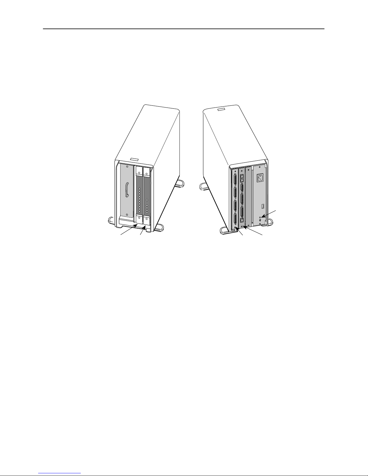
Components
The T1 access unit consists of either a 9161 or 9261 Network Access Module
(NAM) installed in a two-slot or five-slot chassis, along with optional Sync Data,
DSX, or voice Application Modules (APMs) for particular applications. Up to 14
NAMs can also be installed in the 14-slot access carrier.
Slot 01 Slot 02 Slot 01Slot 02
Front View
(without Bezel)
Rear View
Fully Loaded 2-Slot Housing
Ground Screw
and Label
98-15129-02
1-2
April 1998
9161-A2-GH30-30
Page 21

About the T1 Access Mux
2
Ground Screw
and Label
Slot 01
Slot 05
Front View
(without Bezel)
Fully Loaded 5-Slot Housing
Slot 01
Slot 14
Front View
Slot 05
Slot 14
Slot 01
Rear View
Rear View
98-15138-02
Slot 01
98 -15743-0
Fully Loaded Access Carrier
9161-A2-GH30-30
April 1998
1-3
Page 22

6
About the T1 Access Mux
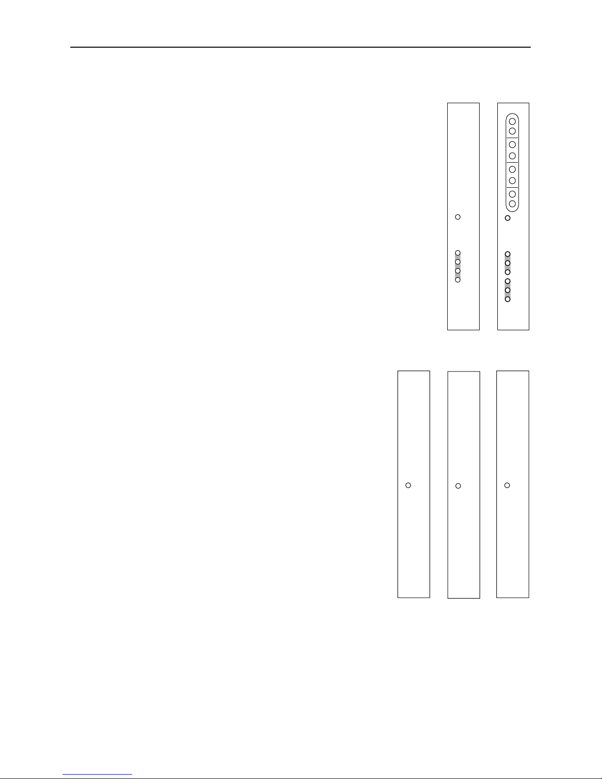
The 9161 Single T1 NAM is equipped with:
One T1 network interface
One DSX-1 drop and insert port
Two DTE interface ports
The 9261 Dual T1 NAM is equipped with:
Two T1 network interfaces
Two DTE interface ports
NET DSX NET MON DSX MON
NETWORK DSX PORT
496-1520
OK
ALM
TST
BKP
SIG
OOF
ALM
SIG
OOF
ALM
1–OK
2–OK
IN
OUT
IN
OUT
IN
OUT
IN
OUT
9161
NET1 NET2 NET1 MON NET2 MON
OK
ALM
TST
BKP
SIG
NET 1 NET 2 PORT
OOF
ALM
SIG
OOF
ALM
1–OK
2–OK
97-15645
IN
OUT
IN
OUT
IN
OUT
IN
OUT
9261
1-4
April 1998
9161-A2-GH30-30
Page 23
4
1
9
There are six APM types:
About the T1 Access Mux
The Synchronous Data APM, which supports:
— Four ports, each supporting EIA-530A, V.35,
RS449, or V.11/X.21
— Rates of Nx56 or Nx64
— Standard RS232-like (RFC 1659) MIB
— Enterprise MIB for testing, statistics, and
some configuration functions
See the
Installation Instructions
9109 Sync Data Application Module (APM)
for more information.
The Dual DSX APM, which supports:
— Two DSX-1 drop and insert ports
See the
(APM) Installation Instructions
9109 Dual DSX Application Module
for more
information.
The E&M Voice APM, which supports:
— E&M Type I, II, IV, or V circuits
— law PCM coding of analog voice line
OK
PORT
496-1515
1–OK
2–OK
3–OK
4–OK
IN
DSX 2 DSX 1 DSX 2 MON DSX 1 MON
OUT
IN
OUT
IN
OUT
9109 SYNC DATA
IN
OUT
9109 DSX
OK
SIG
DSX 1 DSX 2
OOF
ALM
SIG
OOF
ALM
97-15649-01
— Enterprise MIB for testing and
some configuration functions
See the
9109 E&M Analog Voice
Application Module (APM) Installation
Instructions
for more information.
The FXO Voice APM, which supports:
— FXO circuits
— law PCM coding of analog voice line
— Enterprise MIB for testing and some
configuration functions
See the
9109 FXO Analog Voice Application
Module (APM) Installation Instructions
for more information.
The FXS Voice APM, which supports:
— FXS circuits
— law PCM coding of analog voice line
— Enterprise MIB for testing and some
configuration functions
9109 E&M
OK
9109 FXO
OK
9109 FXS
OK
496-1514
97-15648
496-1513
See the
Instructions
9161-A2-GH30-30
9109 FXS Analog Voice Application Module (APM) Installation
for more information.
April 1998
1-5
Page 24

6
7
About the T1 Access Mux
The OCU-DP APM, which supports:
— Either two or six ports
— Speeds of 56 kbps and 64 kbps, as well as 4-wire
Switched 56
— Enterprise MIB for testing and some
configuration functions
Features
See the
9109 OCU-DP Application Module (APM)
Installation Instructions
for more information.
9109 OCU
OK
NOTE:
PORT
The following NAM I/O versions are required to use the
OCU-DP APM:
— SINGLE T1 NAM (870-3389-8000) for the
9161 Single T1 NAM
— DUAL T1 NAM (870-2585-8000) for the
9261 Dual T1 NAM
The T1 access unit offers the following features:
Upgradability. There are three housings to select from: 2-slot, 5-slot and
14-slot access carrier. You can start with a 2-slot housing, and move your
NAM and APM to a 5-slot housing at a later time. Only NAMs may be used in
a 14-slot housing.
1-TST
2-TST
98-1592
PORT
9109 OCU
OK
1-TST
2-TST
3-TST
4-TST
5-TST
6-TST
98-1592
— The 2-slot housing holds one NAM and APM pair.
— The 5-slot housing holds one NAM and up to four APMs, allowing
— As you need additional DTE or voice ports for your network applications,
Modular Design. Any NAM or APM can be physically removed from one
housing and moved to another.
1-6
expansion capability as your network needs grow.
you can add APMs.
April 1998
9161-A2-GH30-30
Page 25

About the T1 Access Mux
Hot Swapping. Provides the ability to insert and remove APMs without
powering-down the housing, and without having to reconfigure the cards
each time they are moved.
The APM configurations travel with the NAM. When an APM is inserted or
removed, the NAM senses that an APM has been inserted or removed, and
can automatically make the appropriate changes to screens, configuration
options, and MIB objects.
— When an APM is inserted in a previously unassigned slot, the T1 access
unit configures the APM using the factory default configuration.
— When the same type of APM is inserted into a previously assigned slot,
the T1 access unit uses the configuration for the APM that previously
occupied the slot; the APM does not have to be reconfigured.
— When another type of APM is inserted into a previously assigned slot, an
alarm and trap are generated for the slot. If accepted, the factory default
configuration is loaded for the new APM type; if rejected, the new APM is
ignored and the previous configuration is retained.
The NAM can be removed without powering down the unit; however, all
system functionality is lost. When a NAM is removed and inserted into
another housing, it applies the NAM’s configurations from the previous
housing to the current housing.
— If the NAM is moved from a 2-slot housing to a 5-slot housing, the
operator can use the configuration of the APM in slot 02 of the previous
housing. APMs in slots 03 – 05 will be configured with the factory default
settings.
— If the NAM is moved from a 5-slot housing to a 2-slot housing, the factory
default configuration options are loaded.
— If the NAM is moved from a 2-slot or a 5-slot housing to a 14-slot
housing, the factory default configuration options are loaded.
Multiple User Interfaces. Provides multiple means for configuring,
operating, managing, and monitoring the unit.
Menu-Driven User Interface.
—
Provides an easy to use, menu-driven
interface for configuring and managing the T1 access unit locally or
remotely.
Access to the user interface can be through an async terminal (or other
VT100-compatible terminal), PC emulation, modem, or a Telnet session.
LED (Light-Emitting Diode) Monitoring.
—
Provides LEDs on the circuit card
faceplates that indicate the status of the card’s operation.
Network Management Capability.
SNMP (Simple Network Management Protocol) Management.
—
network management via an external SNMP management system using
industry-standard and Paradyne-specific MIB (Management Information
Base) objects.
Provides
9161-A2-GH30-30
April 1998
1-7
Page 26

About the T1 Access Mux
Multiple Management Paths. Provides multiple methods for sending/
receiving management data.
—
Embedded Data Link (EDL)
. Provides a path for management data over
a performance channel between two nodes. The performance channel
uses 8 Kbps of bandwidth, and is embedded in the synchronous data
channel. If you choose this method, you must have a Sync Data port.
Direct Data Link (DDL)
—
. Provides a path between two nodes over the
T1/FT1 link itself, embedding the management data in the T1 bundle.
The management data always uses 1 DS0 (64 Kbps).
Facility Data Link (FDL)
—
. Provides the management path over the FDL of
the DS1 extended superframe (ESF). Using this method does not use
any customer data bandwidth, but requires end-to-end connectivity. If you
select this method, you may need to work with your service provider to
ensure that ESF framing is used and the required FDL management path
exists end-to-end.
COM Port
—
. Provides a physical path over the communications
port/interface for local user interface access or network IP connectivity
data management.
IP Connectivity. Supports connectivity within an IP network for up to 300 IP
host and/or network routes. Using the four management paths described
above, provides IP routing for SNMP, Telnet, and file transfer protocol (FTP)
messages connectivity without requiring direct connections.
DSX-1 Drop and Insert port(s) allows DTEs/PBXs that support the DS1
signal format to share the T1 network with other high-speed equipment. One
DSX-1 port is provided on the 9161 T1 NAM. The DSX APM (for use with the
9261 T1 NAM) provides two drop/insert ports.
Alarm and Fault Condition Indication. Provides the capability of attaching
a terminal or printer to display/print alarm messages.
Alarms or traps that are generated include: power supply, loss of signal, out
of frame, alarm indication signal, excessive error rate, primary and secondary
clock failure, yellow alarm signal received, misconfiguration, and APM failure.
1-8
April 1998
9161-A2-GH30-30
Page 27

About the T1 Access Mux
Extensive Testing Capability. Provides the capability to maintain the T1
access unit and diagnose device and network problems via:
Menu-Driven User Interface.
—
Accessed using an async (or other
VT100-compatible) terminal, PC emulation, or Telnet, provides T1
network, DSX-1, sync data port, voice port, and device (lamp) tests.
Loopbacks
that can be selected for an interface include: line, payload,
repeater, remote line, DTE, DTE payload (V.54 loop 3), data channel,
remote data channel (V.54 loop 2 or FT1), V.54, digital, and analog.
Pattern Tests
that can be selected for an interface include: QRSS,
all zeros, all ones, 1-in-8 (T1 interface only), 3-in-24 (T1 interface only),
15
63, 511, 2047, 2
Tone and signal tests
SNMP MIB Object Test Commands
—
-1, 220-1, and 2-byte (user defined).
can also be selected for voice APMs.
. Supports the same testing capability
as the user interface. Paradyne MIBs can be downloaded from our World
Wide Web site. See page A of this manual for our World Wide Web site
address.
Test Jacks
—
. Located on the T1 access unit’s faceplate, support using
external test equipment to perform break-in testing and monitoring of the
T1 network and DSX-1 interfaces. Remove the housing’s bezel to access
these jacks.
Extensive Monitoring Capability. Provides status information to help you
keep track of and evaluate the unit’s and network’s operation via:
Status Branch
—
. Provides system and test status, voice card status for all
eight ports for each card, channel status for all DS0 assignments for all
time slots of the T1 network interface, channel status for all DS0
assignments for all time slots of the DSX-1 interface, and all port
assignments for each voice and data port of both the NAM and APM
cards.
Front Panel.
—
Provides test jacks to monitor the unit’s T1 network and
DSX-1 interfaces, and LEDs to monitor the unit and its interfaces.
Test jacks.
Accessed by removing the housing’s bezel, provide T1
network and DSX-1 monitoring.
LEDs.
Visible without removing the bezel, provide unit and interface
monitoring that includes T1 network and DSX-1 interface received signal
status, as well as synchronous data port statuses.
9161-A2-GH30-30
April 1998
1-9
Page 28

About the T1 Access Mux
Extensive Statistics Gathering. Provides a complete view of the network’s
and each data port’s performance through the statistical data collected from
those interfaces to assist in determining the duration of a condition or event.
— A total of 96 intervals (24 hours) of user and Telco statistical data is kept,
seven per screen page, over a 24 hour period, in 15-minute intervals.
— A total of 32 intervals (8 hours) of Synchronous Data Port statistical data
is kept, over an 8 hour period, in 15-minute intervals.
— Quick and easy access to any of the 96 sets of statistics is provided by
selecting a specific interval or occurrence timeframe. (Specifying an
occurrence timeframe is useful when you know about what time a
specific event occurred.)
— You can select a set of statistics to display at the following times:
following an event, preceding an event, immediately preceding and
following an event, or only those statistics that occurred at or after the
event that is the specified interval or time.
— Statistics collected measure or count the following: errored, unavailable,
severely errored, and bursty errored seconds, as well as controlled slip
seconds and loss-of-frame counts. In addition, yellow alarm, loss of
signal, excessive error rate, frame-synchronization bit error, and
line-code violation counts are kept for each 15-minute interval.
— The worst interval for each statistic is provided as an additional aid in
selecting statistical information surrounding trouble spots.
Configuration Upload/Download and Software Download Capability.
Provides quick, cost-effective software upgrades, and quick transfer of
configuration options to and from nodes using a standard file transfer protocol
(FTP).
Security. Provides multiple levels of security, which prevents unauthorized
access to the unit.
Security can be controlled by:
— Disabling any form of access to the unit.
— Requiring logins (login ID/password/access level combinations), with
three access levels to select from: read-only, limited-access, and
full-access.
— Enabling SNMP management, and specifying a community name and
access level Read or Read/Write.
— Enabling SNMP management, and specifying the IP addresses of only
selected NMSs.
Redundant power supply. Redundant load sharing supply (both AC and DC
versions available) for the 5-slot housing and the access carrier. Protects the
system from a service outage if one power supply fails.
Wall-Mount Bracket. Allows one 5-slot, or up to two 2-slot housings to be
mounted on a wall.
1-10
April 1998
9161-A2-GH30-30
Page 29

Management and Control
Overview
This chapter provides the steps needed to provide management connectivity to
the T1 access unit. You need to select and configure:
A method of local management connectivity for T1 access units.
A method for end-to-end management connectivity across the network.
2
See Appendix B,
and end-to-end management connectivity methods.
IP Addressing
for an IP addressing scheme that fits the local
Configuring Local Management Control
When managing the T1 access unit locally, you can establish a management link
in one of two ways. You can:
Create a management link directly connected through the COM port.
Connect through an external device (modem, LAN adapter, etc.) to the COM
port.
9161-A2-GH30-30
April 1998
2-1
Page 30
Management and Control
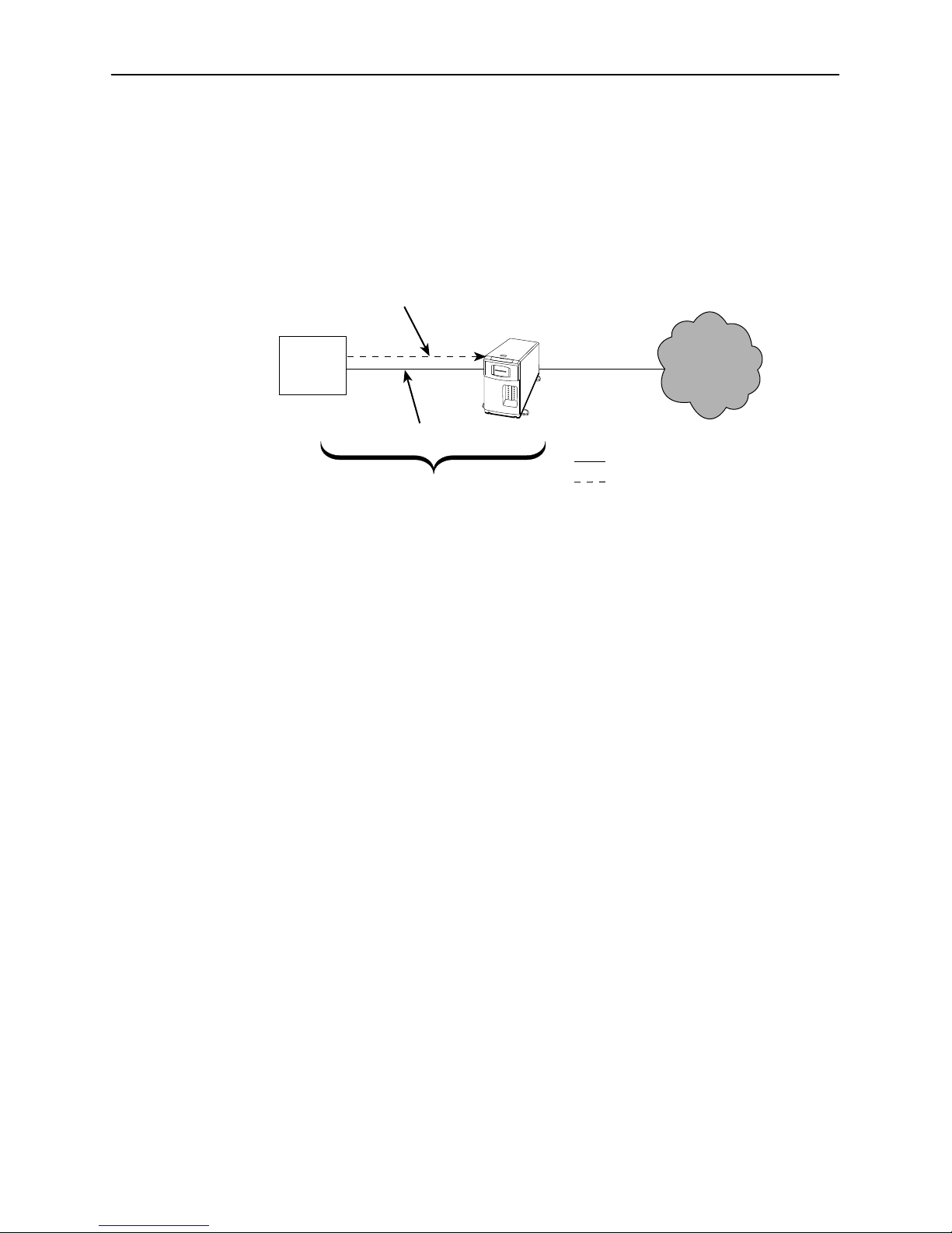
Creating a Management Link Through the COM Port
When the COM port is configured as the IP management link (Net Link), the user
interface is also accessible via Telnet. Although not shown in the illustration
below, a LAN adapter can be connected to the COM port to provide Ethernet or
Token Ring connectivity, or an async terminal (or other VT100-compatible)
interface can be directly connected to the COM port, as well.
Router
Customer Data
DCE
Port
AUX
Port
Management Data
• 2 Cables
– 1 for Management Data
– 1 or more for Customer Data
DTE
Port
COM
Port
T1
Access
Unit
NET
Port
WAN Link
Physical Connection
Customer Data
T1
Network
496-15182
The configuration options below show what should be configured for a
management link. These configuration options are configured from the user
interface based upon the Port Type selected, Asynchronous or Synchronous.
Menu selection sequence:
Main Menu→Configuration→User Interface→Communication Port
Port Use Set to Net Link and
Port Type Set to Asynchronous
Port Use Set to Net Link and
Port Type Set to Synchronous
2-2
— Data Rate (Kbps) — Clock
— Character Length — Data Rate (Kbps)
— Parity
— Stop Bits
— Ignore Control Leads
See Table 5-10, Communication Port Options, in Chapter 5,
April 1998
Setting Up
9161-A2-GH30-30
.
Page 31

Management and Control
When the communication (COM) port is configured as the IP management link,
the async terminal interface is accessible through Telnet.
When this is the case, you also need to enable Telnet session configuration
options.
Menu selection sequence:
Main Menu→Configuration→User Interface→Telnet/FTP Session
You must also have an IP address and a subnet mask assigned.
Menu selection sequence:
Main Menu→Configuration→Management and Communication
See Table 5-12, Telnet/FTP Session Options, in Chapter 5,
In addition, if you want to access the configuration files (upload, download), or
download new firmware files to the T1 access unit, you must set the FTP Session
configuration option to Enable.
Configuring an External Device (Connected to the COM Port)
The T1 access unit can be managed remotely by connecting an external device
like a modem or PAD (packet assembly/disassembly) facility to the COM port.
T1 Access
Unit
COM
Port
External
Modem
WAN Link
T1
Network
PSTN
Simple
ASCII
Interface
Async or
VT100
Terminal
External
Modem
-or-
Setting Up
VT100 Emulation
NMS using SNMP
.
SNMP
NMS
and Telnet or
97-15188-01
Using this out-of-band example, configure call processing using the following
pertinent configuration options, configured from the user interface.
Menu selection sequence:
Main Menu→Configuration→User Interface→External Device (COM Port)
— External Device Commands
— Dial-In Access
— Port Usage
See Table 5-11, External Device (COM Port) Options, in Chapter 5,
9161-A2-GH30-30
April 1998
Setting Up
.
2-3
Page 32

Management and Control
3
Configuring End-to-End Management Control
When managing the T1 access unit remotely, you can establish a management
link across the network in one of three ways. You can:
Use the Facility Data Link (FDL) for a point-to-point ESF T1 link.
Use an Embedded Data Link (EDL) associated with a Sync Data port.
Use a Direct Data Link (DDL).
Management Control Using the ESF FDL
You can configure the T1 access unit to use FDL as a management link if
available for a point-to-point, ESF T1 link, where FDL is end-to-end.
T1 Access
Unit A
LAN
T1
Network
NMS
Physical Connection
FDL
T1 Access
Unit B
496-1518
As shown in the example, in-band management is accomplished through the FDL
between the two T1 access units. Management data for T1 Access Unit B goes to
T1 Access Unit A, which then routes it into the FDL between the units. This
example assumes that the NMS (or Host) that is attempting to access T1 Access
Unit B is attached (using SLIP or PPP) via the COM port on T1 Access Unit A.
Set the Management Link configuration option to FDL.
Menu selection sequence:
Main Menu→Configuration→Network Interface
2-4
April 1998
9161-A2-GH30-30
Page 33

Management Control Using an EDL
4
In the configuration below, the T1 access unit’s management data is multiplexed
with customer data by taking 8 Kbps of the allocated data on a port to use as the
EDL.
There is one configured EDL through the network to each unit:
A shared circuit for management and customer data
T1 Access
Unit C
Management and Control
Port y
Cluster
Controller
Port 1
T1 Access
Unit A
Port 2
T1
Network
Physical Connection
EDL
T1 Access
Unit B
Port x
RouterRouterFEP
496-1518
9161-A2-GH30-30
April 1998
2-5
Page 34

Management and Control
This page intentionally left blank.
2-6
April 1998
9161-A2-GH30-30
Page 35

Applications
Overview
3
This chapter provides information about the following applications:
T1 Access Unit with High Speed Data
T1 Access Unit with High Speed Data and E&M
T1 Access Unit with High Speed Data and APL
T1 Access Unit with High Speed Data, FXS and E&M
T1 Access Unit with High Speed Data and Drop & Insert
Channel Bank Replacement and Additions
Off Premises Extension (OPX)
Direct Inward Dial (DID)
Video Conferencing
Consolidated T1 Access of DDS Circuits
9161-A2-GH30-30
April 1998
3-1
Page 36

Applications
T1 Access Unit with High Speed Data
This application supports two ports of high speed data. The following diagram
depicts a router and a mainframe.
The data moving through the FEP and the cluster controller is heritage data that
is not available on the LAN. Because the T1 access unit includes two data ports,
the router-based data can easily be added to the network without disrupting the
existing network operations.
The data rates available to the two applications can be easily changed. This
allows the router connection to increase in speed. It also allows the FEP-based
data to reduce its data rate as the amount of data transmitted on this route
declines naturally over time.
Cluster
Controller
Terminal
Router
T1 Access
Unit
T1 Access Unit with High Speed Data
T1 Access
Unit
FEP
Router
Mainframe
496-15189
3-2
April 1998
9161-A2-GH30-30
Page 37

T1 Access Unit with High Speed Data and E&M
Analog PBXs (shown in the following diagram) typically communicate on trunk
lines (lines between switches) with a type of communications protocol called
E&M.
The T1 access unit fully supports this application. The T1 access unit supports up
to three 8-port E&M APMs. In the example shown in the diagram, eight time slots
could be assigned to the voice ports, two time slots to the FEP-Cluster controller
link, and up to 14 time slots to the router link. This provides the following:
Voice – Eight telephone calls
FEP-CC – 128 kbps
Router – 896 kbps
Applications
Downtown HQ
Cluster
Controller
Terminal
T1 Access
Unit
Router
PBX PBX
Analog
PBX
Suburban Office
T1 Access
Unit
E&ME&M
T1 Access Unit with High Speed Data and E&M
FEP
Router
Mainframe
Analog
PBX
496-15190
9161-A2-GH30-30
April 1998
3-3
Page 38

Applications
1
T1 Access Unit with High Speed Data and APL
In the example shown in the following diagram, E&M analog voice APMs are
used to transport analog private line (APL) modem traffic instead of voice traffic.
In some parts of the country digital circuits are hard to obtain, and many
applications do not require the higher speeds of digital circuits. This application
allows customers to use existing modems while reducing the cost of using them
by eliminating access lines.
The T1 access unit supports up to three 8-port E&M APMs. A typical application
consists of:
Modem Lines – Eight lines
FEP-CC – 128 kbps
Router – 896 kbps
E&M is used to transport the analog information, and no E&M signaling is
involved. In fact, the E&M signaling leads are disconnected in this application (the
operating mode is set to Transmit Only). See Chapter 4,
information on configuring voice ports.
Setting Up
, for more
Cluster
Controller
Terminal
T1 Access
Unit
Router
(APL Modems)
Suburban Office
T1 Access
Unit
E&M
T1 Access Unit with High Speed Data and APL
Downtown HQ
FEP
Router
Mainframe
497-15191-0
3-4
April 1998
9161-A2-GH30-30
Page 39

T1 Access Unit with High Speed Data, FXS and E&M
1
In the example shown in the following diagram, data and regular voice traffic are
transported by the T1 access unit and the APL modem. E&M-type voice (in
Transmit mode only) is being used to transport the APL modem traffic, while FXS
is employed to transmit regular voice traffic.
Another variation of this application would have the lines connected to the
telephones terminate at a switch in the cloud, where they could be connected to
any other telephone in the world.
Downtown HQ
Applications
Terminal
Router
Cluster
Controller
T1 Access
Unit
Warehouse
T1 Access
Unit
Router
FXS and E&M
Voice
APL
Modems
FEP
Mainframe
497-15192-0
T1 Access Unit with High Speed Data FXS and E&M (Transmit Only Mode)
9161-A2-GH30-30
April 1998
3-5
Page 40

Applications
T1 Access Unit with High Speed Data and
Drop & Insert
In the example shown in the following diagram, voice and data are mixed. The
Drop and Insert feature of the T1 access unit allows voice information to be sent
from a remote site to a large site that contains a digital PBX. People at the distant
end can make calls.
Multiple routers and data lines require adding a Sync Data APM to the T1 access
unit, because more than two data ports are needed.
ServiceAdministration
Router
T1 Access
Unit
Headquarters
T1 Access
Unit
Router
Sales
FXS
Regional Office
T1 or DSX-1
Drop and Insert
PBX
Digital
PBX
T1 Access Unit with High Speed Data and Drop & Insert
Router
Mainframe
97-15193-01
3-6
April 1998
9161-A2-GH30-30
Page 41

Channel Bank Replacement and Additions
In the example shown in the following diagram, the T1 access unit is a
replacement for a channel bank. The T1 access unit is more than just a
replacement for a channel bank. It can do many things that a channel bank
cannot do. A channel bank has no data ports, it passes data as if it comes from
external modems or DSUs. The T1 access unit provides both data and voice
ports. A channel bank is a “dumb” device, and therefore cannot be managed from
a remote site, while the T1 access unit can be managed via SNMP.
Applications
T1 Access Unit
4-Wire
E&M Circuits
PBX
Analog
PBX
with E&M and
FXS APMs
FXS Circuits
to Dial Modems
Channel Bank Replacement
Public Switched
Telephone Network
D4
Switch
97-15194-01
9161-A2-GH30-30
April 1998
3-7
Page 42

Applications
Off-Premises Extension (OPX)
The configuration shown in the following diagram permits a branch location to
access the PBX line as if it were locally connected. Likewise, the branch office
phones appear as if they are locally connected. A call between the two sites does
not result in any long distance charges.
HeadquartersBranch Office
Router
Off-Premises Extension
Direct Inward Dial (DID)
The configuration shown in the following diagram allows an incoming call to dial
to an extension from the PBX, without going through the main switchboard.
Central
Office
(CO)
T1 Facility
T1 Access
Unit
X114
DID Lines
FXS
FXO
X114
T1 Access
Unit
FXO
X111
T1 Access
PBX
Line
PBX
Unit
X113
X112
Router
Mainframe
97-15672
Direct Inward Dial
3-8
PBX
April 1998
97-15673
9161-A2-GH30-30
Page 43

Video Conferencing
The OCU-DP APM supports Switched 56 video as shown in the following
example. Here, an external video codec is connected to OCU-DP ports using
external Switched 56K DSU/CSUs. This connection can be up to 18,000 feet. The
OCU-DP APM converts the 56K digital format from the line side into a digital DS0
format. This DS0 format contains the 56K of data plus the necessary signaling
information required to set up the call to the far-end video equipment.
Applications
Video
Codec
56K
DSU/CSU
Video Conferencing
4-Wire
56K Facility
T1 Access
Mux with
OCU-DP
Cards(s)
T1FT1
Switched
56K
DDS/PSTN
4-Wire
Switched
56K Facility
Video
Codec
Integral 56K
DSU/CSUs
98-15972
9161-A2-GH30-30
April 1998
3-9
Page 44

Applications
Consolidated T1 Access of DDS Circuits
The following example illustrates how to use the OCU-DP APM to reduce facility
costs associated with point-to-point 56/64K connections by consolidating these
lines into a single T1 facility. The T1 Access Muxes shown in this application
could also be used to support both voice and high-speed data.
Typically, T1 Access Muxes are placed at concentration points where a single T1
line is less costly than multiple (typically four or five) 56K lines. If DSUs are left at
both ends of the circuit, proprietary DSU Network Management Systems can be
used. Or, circuits associated with remote DSUs can be terminated directly on a
Sync Data APM at the Data Center to eliminate Data Center DSUs.
The OCU-DP APM does not support subrate DDS rates. Subrate applications can
be supported by installing a Paradyne 3610 or similar device configured for
56/64K line speed.
56 kbps
56 kbps
Data Center
OCU-DP
Card
56 kbps
T1
56 kbps
56 kbps
Remote DSUs
Consolidated T1 Access of DDS Circuits
T1
Public
Network
DCE
Manager
1 or 2
T1s
DSU
Carrier
98-15971
3-10
April 1998
9161-A2-GH30-30
Page 45

User Interface
Introduction
The T1 access unit uses menu-driven asynchronous (async) terminal interface
menus and screens. Along with the LED status indicators on the front panel, the
menu-driven interface provides feedback and status on the:
T1 access unit
DSX-1 and Network T1 interfaces
4
Synchronous data ports
Voice ports
Async Terminal User Interface Access
You can access the user interface:
Locally through a direct connection to the communications port via an async
terminal (or other VT100-compatible terminal) or PC emulation.
Remotely through a Telnet session, although only one user interface session
may be active at one time.
Network Management
Manage the T1 access unit via an SNMP management system connected to the
communications port or through a remote in-band connection.
Menu Hierarchy
The menu hierarchy represents the organization of the system’s menus and
screens. Refer to the enclosed
hierarchy.
Quick Reference
for a pictorial view of the menu
9161-A2-GH30-30
April 1998
4-1
Page 46

User Interface
Main Menu Screen
Access to all of the T1 access unit’s tasks begins at the Main Menu screen, which
has four menus or branches.
The login’s access level appears at the top of the screen unless no security has
been set up. Menu branches are filtered based on effective security level, which
is the lower of the Session Access Level (Telnet/FTP Session options) and the
Login ID access level (Administer Logins under the Control branch).
Select . . .
Status View diagnostic tests, voice interfaces, cross
Test Select, monitor, and cancel test for the system’s
Configuration Display and edit the configuration options. 1, 2, 3
Control Control the user interface for call setup, device
Screen Field Types
Three types of screen fields are available on the async terminal.
Use screen field . . .
Menu selection Display a list of available functions for user selection.
To . . . Security Level
1, 2, 3
connections, statistics, and T1 access unit
identity information.
1, 2
interfaces.
1
naming, date and time, login administration,
and system alarm relay cut-off (for the 5-slot
housing). Also, initiate a power-on reset of the
system.
To . . .
Input Add or change information on a screen.
Display Display configuration information and results from
4-2
Underlines in the field value or selection indicate an input
or edit field.
performance and system-specific tests.
No underlines in the field value or selection indicate a
display-only field.
April 1998
9161-A2-GH30-30
Page 47

What Affects Screen Displays
What appears on the screens depends on:
Current configuration – How your T1 access unit is currently configured.
Security access level – The security level set by the system administrator
for each user.
Data selection criteria – What you entered in previous fields or screens.
Screen Work Areas
There are two user work areas:
Screen area – Where you input information into fields.
Screen function key area – Where you perform specific screen functions.
Following is a sample async terminal interface screen.
User Interface
9161-A2-GH30-30
April 1998
4-3
Page 48

User Interface
Menu Path
Device
Name
Screen
Area
Screen
Function
Key Area
Message Area
System
Access Level
Model Number
Date and Time
main Access Level: 1 Company Name 9162
Device Name: Node A 01/26/96 23:32
MAIN MENU
Status
Test
Configuration
Control
–––––––––––––––––––––––––––––––––––––––––––––––––––––––––––––––––––––––––––––––
Ctrl-a to access these functions E
S
ave
xit
Screen Format Description
Menu path Menu selections made to reach the current screen.
Device name Customer-assigned identification of the system.
Access level Currently assigned security access level.
Company Name Vendor company name.
Model number
Date and Time Date and Time kept locally by the system
Screen area Selection, display, and input fields for monitoring and
Screen function keys Specific functions that can be performed on the
System messages and
field values
xxxx
The T1 access unit’s model number:
9162 – 9161 Single T1 NAM in 2-slot housing
9165 – 9161 Single T1 NAM in 5-slot housing
9262 – 9261 Dual T1 NAM in 2-slot housing
9265 – 9261 Dual T1 NAM in 5-slot housing
9161 – 9161 Single T1 NAM in 14-slot housing
9261 – 9261 Dual T1 NAM in 14-slot housing
(24-hour clock).
maintaining the system.
screen.
System-related information, valid values for input
fields, and System Health and Status messages.
4-4
April 1998
9161-A2-GH30-30
Page 49

Navigating the Screens
You can navigate the screens by:
Using keyboard keys
Switching between the two screen work areas
Using screen function keys
Keyboard Keys
Use the following keyboard keys to navigate within the screens.
User Interface
To . . .
Move cursor between the screen area and
the screen function keys area
Return to the previous screen Esc
Move cursor to the next field Right Arrow (on same screen row), or
Move cursor to the previous field Left Arrow (on same screen row), or
Move cursor one position to the left. If the
cursor is at the beginning of a field,
Backspace has no effect.
Move cursor to the first character of the
previous field (backtab)
Display the next valid value for the field Spacebar
Delete character that the cursor is on Delete (Del)
Move cursor up one field within a column on
the same screen
Move cursor down one field within a column
on the same screen
Press . . .
Ctrl-a
Tab (on any screen row)
Ctrl-k
Backspace
Ctrl-k
Up Arrow or Ctrl-u
Down Arrow or Ctrl-d
Move cursor one character to the right if in
edit mode
Move cursor one character to the left if in edit
mode
Redraw the screen display, clearing
information typed in but not yet entered
Accept entry or display valid options on the
last row of the screen when pressed before
entering data or after entering invalid data
9161-A2-GH30-30
April 1998
Right Arrow or Ctrl-f
Left Arrow or Ctrl-b
Ctrl-l
Return (Enter)
4-5
Page 50

User Interface
Screen Function Keys
All screen function keys (located in the lower part of the screen) operate the
same way (upper- or lowercase) throughout the screens.
These keys use the following conventions:
For the screen
Select . . .
M or m MainMenu Return to the Main Menu screen.
E or e Exit Terminate the async terminal session.
N or n New Enter new data.
O or o Modify Modify existing data.
L or l Delete Delete data.
S or s Save Save information.
R or r Refresh Update screen with current information.
function . . .
And press Return to . . .
C or c ClrStats Clear network performance statistics and refresh the
screen.
U or u PgUp Display the previous page.
D or d PgDn Display the next page.
4-6
April 1998
9161-A2-GH30-30
Page 51

Selecting from a Menu
You select from a menu to get subsequent menus or screens so you can perform
desired tasks.
" Procedure
To make a menu selection:
User Interface
1. Tab or press an arrow key to position the cursor on a menu selection. Each
menu selection is highlighted as you press the key to move the cursor from
position to position.
2. Press Return. The selected menu or screen appears.
3. Continue Steps 1 and 2 until you reach the screen you want.
Refer to the
Selecting a Field
Once you have reached the desired menu or screen, select a field to view,
change, or issue a command. Select a field from within a menu in the same way
you select from a menu – press the Tab or right arrow key.
Example:
Selecting Control from the Main Menu, selecting Administer Logins, then entering
or changing security information.
Making Input Selections
You can enter information into a field in one of several ways. Once the field is
selected, you can:
H Manually type in (enter) the field value or command.
H Type in (enter) the first letter(s) of a field value or command, using the
Quick Reference
to guide you through menu selections.
Example:
Entering
Control menu/branch).
character matching feature.
abc
as a user’s Login ID on the Administer Logins screen (from the
Example:
When configuring an FXS voice port’s operating mode with the Operating
Mode configuration option/field selected (values FXS, FXSDN,
FXSDN/WINK, PLAR and DPO), entering f or F displays the first value
fxsd
or
FXSD
starting with f – FXS. In this example, entering
FXSDN as the selection.
would display
H Switch from the screen area to the screen function area and select or enter
the designated screen function key. See
Areas
H Press the spacebar to make the next valid choice.
9161-A2-GH30-30
for an example.
April 1998
Switching Between Screen Work
4-7
Page 52

User Interface
Switching Between Screen Work Areas
Use Ctrl-a to switch between the two screen work areas to perform all screen
functions.
" Procedure
1. Press Ctrl-a to switch from the screen area to the screen function key area.
2. Select either the function’s designated (underlined) character or Tab to the
desired function key.
Example:
Enter e or E to Exit.
3. Press Return. The function is performed.
4. To return to the screen area, press Ctrl-a again.
Accessing the User Interface
T1 access unit connectivity can be established via a directly-connected terminal.
However, if for some reason you cannot access the user interface, do one of the
following:
H Reset COM Port – Allows you to reset the configuration options related to
COM port usage. This also causes a device reset, where the T1 access unit
performs a Device Self-Test. No security-related configuration options are
changed.
H Reload Factory Defaults – Allows you to reload the Default Factory
Configuration, resetting all of the configuration and control settings. This
method is also useful when the user’s password(s) have been forgotten.
Selecting this method also causes a device reset.
" Procedure
To reset COM port settings:
1. Attach the async terminal to the COM port.
2. At the async terminal, configure the terminal to operate at 19.2 kbps, using
character length of 8 bits, with one stop-bit, and no parity.
3. Ensure that any hardware or software flow control is disabled.
4. Reset the T1 access unit, then immediately and repeatedly press Return at a
rate of at least 1 press per second until the System Paused screen appears.
5. Tab to the desired method, and enter yes (or y) for the selected prompt.
4-8
April 1998
9161-A2-GH30-30
Page 53

User Interface
If entering yes to prompt . . . Then . . .
Reset COM Port usage Port Type is set to Terminal.
Data Rate (Kbps) is set to 19.2.
Character Length is set to 8.
Stop Bits is set to 1.
Parity is set to None.
External Device Commands is set to Disable.
Reload Factory Defaults All factory-loaded configuration and control
settings contained in the Default Factory
configuration area are loaded.
If no (or n) is entered, or if no selection is made within 30 seconds, the T1
access unit returns to the condition of operation it was in when the system
pause was initiated, with the COM port settings returning to their configured
states.
If you chose yes, the T1 access unit resets itself, going through a Device
Self-Test. Connectivity is restored and the Main Menu screen appears.
9161-A2-GH30-30
April 1998
4-9
Page 54

User Interface
This page intentionally left blank.
4-10
April 1998
9161-A2-GH30-30
Page 55

Setting Up
Considerations When Setting Up
When setting up the system, you need to:
Arrange for T1 service.
5
Plan your channel map. See
more information.
Choose a management configuration. Decide how you want to manage the
system:
— Locally through the T1 access unit’s communications (COM) port either
directly or remotely through a modem.
— Through an asynchronous terminal interface or Telnet session, or through
an SNMP NMS.
Determine whether you want alarms generated and how you would like the
system to communicate alarm information to an ASCII terminal/printer or a
management system.
you how to set alarms.
Determine whether you want traps generated and how you would like the
system to communicate trap information to an ASCII terminal/printer or a
management system.
you how to set SNMP traps.
If you are managing the system using an SNMP NMS or Telnet, select an IP
addressing scheme.
Configuring for Alarms and Traps
Setting Up for SNMP Management
Assigning Cross Connections
on page 5-64 tells
on page 5-70 tells
on page 5-36 for
9161-A2-GH30-30
April 1998
5-1
Page 56

Setting Up
Selecting a Management Interface
Select one of the following management interfaces:
Asynchronous terminal interface – Over the T1 access unit’s COM port for
local configuration and control when the system does not include an NMS.
An asynchronous terminal interface is also required for initial setup that
enables external management.
Telnet access to an asynchronous terminal interface – Over the T1 access
unit’s COM port, through the ESF Facility Data Link (FDL), via an associated
EDL (EDL) or Direct Data Link (DDL).
SNMP – SNMP manager(s) using the SNMP protocol to configure and
control the unit using standard MIBs and enterprise-specific MIB extensions.
Logins
Refer to Chapter 6,
Security
, to learn how to create and delete logins.
5-2
April 1998
9161-A2-GH30-30
Page 57

Adding System Identity Information
Use the Device Name screen to identify this system, and to change or display the
general name, location, and contact for the system.
Procedure
1. Follow this menu selection sequence:
Main Menu→Control→Device Name
2. Use the Tab key to move the cursor to the field where you want to add or
change information.
NOTE:
To clear existing information, place the cursor in the Clear field and press
Return.
Setting Up
If the selection is . . .
Device Name Unique name for device identification of up to
System Name SNMP system name; can be up to 255 characters.
System Location Your system’s physical location; can be up to
System Contact Name and how to contact the person responsible for this
3. To save changes, select Save and press Return.
When Save is complete, Command Complete appears in the message area
at the bottom of the screen.
Enter the . . .
20 characters.
255 characters.
system; can be up to 255 characters.
9161-A2-GH30-30
April 1998
5-3
Page 58

Setting Up
Setting Date and Time
Use the Date & Time screen to set the date and time for the system.
" Procedure
1. Follow this menu selection sequence:
Main Menu→Control→Date & Time
2. Use the Tab key to move the cursor to the field where you want to add or
change information.
NOTE:
To clear existing information, move the cursor to the Clear field and press
Return.
If the selection is . . .
Date (mm/dd/yy) Date in the format mm/dd/yy or mm-dd-yy .
Time (hh:mm) Time (24-hour clock) in the format hh:mm.
3. To save changes, select Save and press Return.
When Save is complete, Command Complete appears in the message area
at the bottom of the screen.
Configuring the T1 Access Unit
Your system comes preconfigured with factory default settings as noted in the
configuration option tables in this chapter, as well as on the Quick Reference. If
you need to display or change these settings, use the system’s Configuration
branch.
To change configuration option settings you must perform the following tasks:
H Access and display configuration option settings
H Change configuration option settings
H Save configurations option settings to a configuration option area
Enter the . . .
NOTE:
Only Security Access Level 1 users can change configuration options.
Security Access Level 2 and 3 users can just view configuration options.
5-4
April 1998
9161-A2-GH30-30
Page 59

Recommended Order of Configuration
The menu tree is organized in the recommended order of configuration. See
Appendix A,
Menus and Configuration Worksheets
system layout. Use the worksheets to keep track of the configuration option
settings.
Configuration Option Areas
The T1 access unit offers four configuration option storage areas:
Setting Up
, for a graphical view of the
Configuration Option Area
Current Configuration The T1 access unit’s set of currently active
Customer Configuration 1 The first of two alternate sets of configurations that can
Customer Configuration 2 The second of two alternate sets of configurations that
Default Factory Configuration A read-only configuration area containing the factory
Description
configuration options.
be set up by the customer and stored for future use.
can be set up by the customer and stored for future use.
default configuration options.
You can load and edit the default factory configuration
settings, but you can only save those changes to the
Current, Customer 1, and Customer 2 configuration
option areas.
The Current, Customer 1, and Customer 2 configuration
option areas are identical to the Default Factory
Configuration until modified by the customer.
Accessing and Displaying Configuration Options
To access and display the configuration options, you must first load (copy) the
applicable configuration option set into the edit area.
NOTE:
If your T1 access unit is operating at any speed other than the default
(19.2 kbps) and you attempt to load factory default configuration options, you
could lose your communication link.
Procedure
1. Follow this menu selection sequence:
2. The Load Configuration From screen appears. Select the configuration option
area you want to load and press Return. The selected configuration option
set is loaded into the configuration edit area and the Configuration
Edit/Display screen appears.
9161-A2-GH30-30
Main Menu→Configuration
April 1998
5-5
Page 60

Setting Up
Changing Configuration Options
Once the Configuration is loaded, use the Configuration Edit/Display screen to
display, change, and save a configuration in one of the configuration areas.
Procedure
1. From the Configuration Edit/Display screen, select the configuration option
set you want to view or make changes to and press Return.
2. Select the configuration options applicable to your network, and make
appropriate changes to the setting(s).
3. Repeat Steps 1 and 2 until all changes are complete.
Saving Configuration Options
When all changes to the configuration options are complete, use the Save
function key to save configuration option changes to either the Current,
Customer 1, or Customer 2 configuration areas.
Procedure
1. Press Ctrl-a to switch to the screen function key area.
2. Select the S
and press Return. The Save Configuration To screen appears.
3. Select the configuration option area where you want to save the changes to
and press Return.
When Save is complete, Command Complete appears in the message area
at the bottom of the screen.
ave function key from any of the Configuration branch screens
NOTE:
If you changed configuration options and try to exit the Configuration
branch without saving those changes, a Save Configuration screen
appears requiring a Yes or No response to saving the changes.
If you select . . .
No Main Menu screen appears. Changes are not saved.
Yes Save Configuration To screen appears. Choose a
Then the . . .
configuration option area to save to (e.g., Customer
Configuration 1).
5-6
April 1998
9161-A2-GH30-30
Page 61

Configuring T1 and DSX-1 Interfaces
You can configure the following interfaces:
Network Interface
DSX-1 Interface (if applicable)
Configuring the Network Interface
Use the Network Interface Options screen to configure the network interface on
the T1 NAM (see Table 5-1).
Configuration Edit/Display→Network
If you have a 9261 Dual T1 NAM, select the desired Network interface, 1 (default)
or 2, in the NETWORK field. For the 9161 Single T1 NAM, this field is read-only
and always displays a 1.
Table 5-1. Network Interface Options (1 of 7)
Setting Up
Interface Status
Possible Settings: Enable, Disable
Default Setting: Disable for Network interface 1
Specifies whether the interface selected in the Network field is available for use.
Interface Status is read-only if Network is set to 1 (first interface on the 9261 Dual
T1 NAM, or the interface on the 9161 Single T1 NAM).
Enable – The interface is available.
Disable – The interface is not available for use. When the interface is disabled, any
existing cross-connect assignments for this interface will be cleared, no alarms or traps
for this interface will be generated, no configuration options will be displayed, and all
LEDs associated with this interface will remain off. If you attempt to disable the
Network 2 interface for which cross connections exist, the message This action will
clear all Network
No – The operation is cancelled.
Yes – The following occurs:
All existing cross-connect assignments for this interface are cleared.
Alarms or traps associated with this interface are not generated.
LEDs associated with this interface are held in an “off’’ state.
Line Framing Format
Possible Settings: D4, ESF
Default Setting: ESF
Specifies the framing format for transmitted and received signals on the T1 network
interface.
D4 – Uses D4 framing format.
ESF – Uses Extended Superframe (ESF) framing format.
Enable for Network interface 2
n
Cross Connections. Are You Sure? No appears. If you select:
9161-A2-GH30-30
April 1998
5-7
Page 62

Setting Up
Table 5-1. Network Interface Options (2 of 7)
Line Coding Format
Possible Settings: AMI, B8ZS
Default Setting: B8ZS
Specifies the line coding format for the network interface.
AMI – Uses Alternate Mark Inversion (AMI) line coding format.
B8ZS – Uses Bipolar 8 Zero Suppression (B8ZS) line coding format.
Line Build Out (LBO)
Possible Settings: 0.0, –7.5, –15, –22.5
Default Setting: 0.0
Specifies the line build out for the signal transmitted to the network.
0.0, –7.5, –15, –22.5 – Specifies line build out in dB.
Bit Stuffing
Possible Settings: 62411, Part68, Disable
Default Setting: 62411
Determines the type of bit insertion to provide ones density requirements for data
transmitted to the network.
Bit Stuffing does not appear if Line Coding Format is set to B8ZS.
62411 – Inserts a one in the data after 15 consecutive zeros are received or the density
of ones falls below 12.5%. This setting complies with A T&T TR 62411.
Part68 – Inserts a one in the data if 80 consecutive zeros are received or the density of
ones falls below 12.5%.
Disable – Does not enforce ones density on the data sent to the network.
Network Initiated LLB
Possible Settings: Enable, Disable
Default Setting: Enable
Allows the initiation and termination of the line loopback (LLB) to be controlled by the
receipt of LLB-Actuate and LLB-Release commands from the network.
Enable – LLB is controlled by LLB-Actuate and LLB-Release commands. Receiving a
LLB-Actuate command causes the NAM to enter a line loopback (provided an LLB can
be performed in the T1 access unit’s current state). Receiving a LLB-Release command
terminates the LLB.
Disable – The T1 access unit ignores the LLB-Actuate and LLB-Release commands.
NOTE: When disabled, the NAM is not in compliance with ANSIT1.403 or
A T&T TR 62411.
5-8
April 1998
9161-A2-GH30-30
Page 63

Setting Up
Table 5-1. Network Interface Options (3 of 7)
Network Initiated PLB
Possible Settings: Enable, Disable
Default Setting: Enable
Allows the initiation and termination of the payload loopback (PLB) to be controlled by
the receipt of PLB-Actuate and PLB-Release commands from the network.
Network Initiated PLB only appears if Line Framing Format is set to ESF.
Enable – PLB is controlled by PLB-Actuate and PLB-Release commands. Receiving a
PLB-Actuate command causes the T1 access unit to enter a payload loopback
(provided a PLB can be performed in the NAM’s current state). Receiving a
PLB-Release command terminates the PLB.
Disable – The T1 access unit ignores the PLB-Actuate and PLB-Release commands.
NOTE: When disabled, the unit is not in compliance with ANSIT1.403 or
Transmit T iming
Possible Settings: System, Network
Default Setting: System
Allows transmit timing to be selected from either the system master clock source or from
the currently selected network interface.
Transmit Timing only appears for the 9261 Dual T1 NAM.
System – Transmit timing is derived from the current system clock source (set using
System Options, see Table 5-9).
Network – Transmit timing is derived from this interface.
NOTE: When Network is configured, the clock must be synchronized to the system
A T&T TR 54016.
clock source.
ANSI Performance Report Messages
Possible Settings: Enable, Disable
Default Setting: Disable
Specifies whether ANSI T1.403 compliance performance report messages (PRMs) are
generated and sent to the network over the ESF FDL every second.
ANSI Performance Report Messages only appears if Line Framing Format is set
to ESF.
Enable – Generates and sends PRMs.
Disable – Does not generate and send PRMs.
9161-A2-GH30-30
April 1998
5-9
Page 64

Setting Up
Table 5-1. Network Interface Options (4 of 7)
Management Link
Possible Settings: Disable, FDL, DDL
Default Setting: Disable
Specifies the network management link.
NOTES: – If both FDL and DDL are not available selections, the configuration
option is set to Disable and cannot be edited.
– If Management Link for the local T1 access unit is set to FDL or DDL,
configure the remote T1 access unit with the same settings.
Disable – Does not use the management link.
FDL – Uses FDL as the management link. FDL allows IP management traffic to flow
over the 4 kbps data link provided by the FDL. FDL requires an end-to-end FDL
connection and cannot be terminated within the network.
FDL does not appear if:
– Line Framing Format is set to D4.
– EDL on any synchronous data port is set to Enable.
DDL – Uses DDL as the management link.
DDL does not appear if all network time slots are assigned.
IP Address
Possible Settings: 000.000.000.000 – 223.255.255.255, Clear
Default Setting: 000.000.000.000
Specifies the internet protocol address for the management link.
IP Address only appears if Management Link is set to FDL or DDL.
000.000.000.000 – 223.255.255.255 – The IP address for the management link which
you can view or edit. The first digit (i.e.,
xxx
.255.255.255) cannot be 0 or 127, or greater
than 223. However, 000.000.000.000 is valid, representing a null address.
Clear – Resets the IP address and fills the address with zeros.
Subnet Mask
Possible Settings: 000.000.000.000 – 255.255.255.255, Clear
Default Setting: 000.000.000.000
Specifies the subnet mask for the management link.
Subnet Mask only appears if Management Link is set to FDL or DDL.
000.000.000.000 – 255.255.255.255 – The subnet mask for the management link which
you can view or edit.
Clear – Resets the node subnet mask and fills the address with zeros
(i.e., 000.000.000.000). When the subnet mask is all zeros, the IP protocol creates a
default subnet mask based on the class of the IP address: Class A: 255.000.000.000,
Class B: 255.255.000.000, or Class C: 255.255.255.000.
5-10
April 1998
9161-A2-GH30-30
Page 65

Setting Up
Table 5-1. Network Interface Options (5 of 7)
Routing Information Protocol
Possible Settings: None, Proprietary
Default Setting: Proprietary
Specifies whether routing information protocol (RIP) is used for routing of management
information between NAMs.
Routing Information Protocol only appears if Management Link is set to FDL or
DDL.
None – No routing protocol is used. Use this setting when the device at the other end of
the management link cannot accept routing information.
Proprietary – A proprietary variant of RIP version 1 is used to communicate routing
information between NAMs to enable the routing of IP traffic.
Network Time Slot
Possible Settings: 01 – 24
Default Setting: lowest available time slot
Specifies the time slot for the DDL management link.
Network Time Slot only appears appears if Management Link is set to DDL.
NOTE: If Management Link is not set to DDL, the assigned time slot will be set to
01 – 24 – V alid settings consist of any unassigned time slot within the 01 – 24 range.
Circuit Identifier
unassigned.
Possible Settings: T ext Field, Clear
Default Setting: blank
Identifies the transmission vendor’s circuit information for the purpose of facilitating
troubleshooting.
T ext Field – Edit or display circuit identifier information (maximum 255 characters).
Clear – Removes the circuit identifier information.
Loss of Signal (LOS) Alarm
Possible Settings: Enable, Disable
Default Setting: Enable
Specifies whether an alarm message is generated when a loss of signal condition is
detected on the network interface.
Enable – Generates an ASCII alarm message.
Disable – Does not generate an ASCII alarm message.
Out of Frame (OOF) Alarm
Possible Settings: Enable, Disable
Default Setting: Enable
Specifies whether an alarm is generated when an out-of-frame condition is detected on
the network interface.
Enable – Generates an alarm message.
Disable – Does not generate an ASCII alarm message.
9161-A2-GH30-30
April 1998
5-11
Page 66

Setting Up
Table 5-1. Network Interface Options (6 of 7)
Alarm Indication Signal (AIS) Alarm
Possible Settings: Enable, Disable
Default Setting: Enable
Specifies whether an alarm message is generated when an alarm indication signal
condition is detected on the network interface.
Enable – Generates an ASCII alarm message.
Disable – Does not generate an ASCII alarm message.
Yellow Alarm
Possible Settings: Enable, Disable
Default Setting: Enable
Specifies whether an alarm message is generated when a yellow alarm condition is
detected on the network interface.
Enable – Generates an ASCII alarm message.
Disable – Does not generate an ASCII alarm message.
Excessive Error Rate (EER) Alarm
Possible Settings: Enable, Disable
Default Setting: Enable
Specifies whether an alarm message is generated when an excessive error rate
condition is detected on the network interface.
Excessive Error Rate only appears if Line Framing Format is set to ESF.
Enable – Generates an ASCII alarm message.
Disable – Does not generate an ASCII alarm message.
5-12
April 1998
9161-A2-GH30-30
Page 67

Setting Up
Table 5-1. Network Interface Options (7 of 7)
Excessive Error Rate Threshold
Possible Settings: 10E-4, 10E-5, 10E-6, 10E-7, 10E-8, 10E-9
Default Setting: 10E-4
Sets the error rate threshold that determines when an excessive error rate (EER)
condition is declared. The excessive error rate is determined by the ratio of the number
of CRC6 errors to the total number of bits received over a set period of time.
Excessive Error Rate Threshold only appears if Line Framing Format is set to
ESF.
10E-4 – Declares an EER if more than 1,535 CRC6 errors are detected in a 10-second
period. Clears when fewer than 1,536 CRC6 errors are detected within the same time
period.
10E-5 – Declares an EER if more than 921 CRC6 errors are detected in a 60-second
period or a 10
detected within the same time period.
10E-6 – Declares an EER if more than 92 CRC6 errors are detected in a 60-second
period or a 10
detected within the same time period.
10E-7 – Declares an EER if more than 9 CRC6 errors are detected in a 60-second
period or a 10
errors are detected within the same time period.
10E-8 – Declares an EER if more than 41 CRC6 errors are detected in three 15-minute
intervals or a 10–7, 10–6, 10–5, 10–4 condition occurs. Clears when fewer than 42 CRC6
errors are detected within the same time period.
10E-9 – Declares an EER if more than 4 CRC6 errors are detected in three 15-minute
intervals or a 10
5 CRC6 errors are detected within the same time period.
–4
condition occurs. Clears when fewer than 922 CRC6 errors are
–5
or 10–4 condition occurs. Clears when fewer than 93 CRC6 errors are
–6
, or 10–5, or 10–4 condition occurs. Clears when fewer than 10 CRC6
–8
, 10–7, 10–6, 10–5, or 10–4 condition occurs. Clears when fewer than
9161-A2-GH30-30
April 1998
5-13
Page 68

Setting Up
Configuring the DSX-1 Interface
Use the DSX-1 Interface Options screen to configure the DSX-1 interface on the
T1 NAM (see Table 5-2).
Configuration Edit/Display→DSX-1
NOTE:
If the DSX-1 interface is disabled, Disable appears on the screen. No other
options are shown.
If you are using a Dual DSX APM, enter the port number of the desired DSX-1
interface in the PORT field. For the DSX port on the 9161 Single T1 NAM, a 1 is
displayed and is read-only.
Table 5-2. DSX-1 Interface Options (1 of 3)
Interface Status
Possible Settings: Enable, Disable
Default Setting: Disable
Determines if the DSX-1 interface is provided by the port.
Enable – The DSX-1 interface port transmits and receives data.
Disable – The DSX-1 interface port does not transmit or receive data. If time slots are
assigned to the DSX-1 interface when an attempt is made to disable this configuration
option, the message This action will clear all DSX-1 Cross Connections. Are Y ou
Sure? No appears. If you select:
No – The operation is cancelled.
Yes – The following occurs:
All existing DSX-1 interface cross-connect assignments are cleared.
Alarms or traps associated with the DSX-1 interface are not generated.
LEDs associated with the DSX-1 interface are held in an “off’’ state.
5-14
Line Framing Format
Possible Settings: D4, ESF
Default Setting: ESF
Specifies the framing format for transmitted and received signals on the DSX-1
interface.
D4 – Uses D4 framing format.
ESF – Uses Extended Superframe (ESF) framing format.
Line Coding Format
Possible Settings: AMI, B8ZS
Default Setting: B8ZS
Specifies the line coding format for the DSX-1 interface.
AMI – Uses Alternate Mark Inversion (AMI) line coding format.
B8ZS – Uses Bipolar 8 Zero Suppression (B8ZS) line coding format.
April 1998
9161-A2-GH30-30
Page 69

Setting Up
Table 5-2. DSX-1 Interface Options (2 of 3)
Line Equalization
Possible Settings: 0–133, 133–266, 266–399, 399–533, 533–655
Default Setting: 0–133
Permits a standard DSX signal to be delivered over a distance of up to 655 feet.
0–133 – Equalization on the DSX-1 side allows up to 133 feet of cable between the
NAM and the DTE.
133–266 – Equalization on the DSX-1 side allows up to 266 feet of cable between the
NAM and the DTE.
266–399 – Equalization on the DSX-1 side allows up to 399 feet of cable between the
NAM and the DTE.
399–533 – Equalization on the DSX-1 side allows up to 533 feet of cable between the
NAM and the DTE.
533–655 – Equalization on the DSX-1 side allows up to 655 feet of cable between the
NAM and the DTE.
Send All Ones on DSX-1 Failure
Possible Settings: Enable, Disable
Default Setting: Enable
Determines whether action is taken when a valid signal cannot be recovered for the
DSX-1 (LOS, continuous OOF, or AIS).
Enable – Sends all ones on the DS0 channels allocated to the DSX-1 interface in the
event of an LOS, AIS, or continuous OOS condition on the DSX-1 interface.
Disable – No action is taken when a signal fails on the DSX-1 interface. The data
received is passed through the network interface channels unchanged.
Loss of Signal (LOS) Alarm
Possible Settings: Enable, Disable
Default Setting: Enable
Specifies whether an alarm message is generated when a loss of signal condition is
detected on the DSX-1 interface.
Enable – Generates an ASCII alarm message.
Disable – Does not generate an ASCII alarm message.
Out of Frame (OOF) Alarm
Possible Settings: Enable, Disable
Default Setting: Enable
Specifies whether an alarm message is generated when an out-of-frame condition is
detected on the DSX-1 interface.
Enable – Generates an ASCII alarm message.
Disable – Does not generate an ASCII alarm message.
9161-A2-GH30-30
April 1998
5-15
Page 70

Setting Up
Table 5-2. DSX-1 Interface Options (3 of 3)
Alarm Indication Signal (AIS)
Possible Settings: Enable, Disable
Default Setting: Enable
Specifies whether an alarm message is generated when an alarm indication signal
condition is detected on the DSX-1 interface.
Enable – Generates an ASCII alarm message.
Disable – Does not generate an ASCII alarm message.
Yellow Alarm
Possible Settings: Enable, Disable
Default Setting: Enable
Specifies whether an alarm message is generated when a yellow alarm condition is
detected on the DSX-1 interface.
Enable – Generates an ASCII alarm message.
Disable – Does not generate an ASCII alarm message.
Configuring Ports
Configure the following ports on the T1 NAM and any APMs that are installed in
your system.
Sync Data ports on the T1 NAM or the Sync Data APM
Voice ports on the FXS, FXO and E&M APMs
Once you have a port configured, you can copy that configuration to other ports
of the same type (see
Configuring Sync Data Ports
Use the Synchronous Data Port Options to configure the synchronous data
port(s) on the T1 NAM or on any Sync Data APM associated with the NAM (see
Table 5-3).
Configuration Edit/Display→Sync Data Ports
NOTE:
If the selected Synchronous Data Port is disabled, Disable appears on the
screen. No other options are shown.
Copying Port Configurations
on page 5-35).
The Synchronous Data Port Options screen appears for Port 1 of the first slot
containing a Sync Data APM. If desired, enter the slot and port number of
another sync data port.
5-16
April 1998
9161-A2-GH30-30
Page 71

Setting Up
Table 5-3. Synchronous Data Port Options (1 of 7)
Port Status
Possible Settings: Enable, Disable
Default Setting: Disable
Determines whether the synchronous data port is being used and can be configured.
Synchronous data port options do not appear if Port Status is set to Disable.
Enable – The port is active, and can be used to transmit and receive data.
Disable – The port is not active. When the port is disabled, the following will occur:
No alarms or traps configured for the port will be generated.
LED for the port will be held in an Off state.
Existing cross-connect assignments associated with the port will be cleared. The
message This action will clear any Cross Connections for the Port. Are You
Sure? No
No – The operation is cancelled. (Pressing either the Esc or Ctrl-a key acts as a
No.)
Yes – Port status is disabled.
Port Type
Possible Settings: E530, V.35, RS449, X.21
Default Setting: E530
Selects the synchronous data port type for the data port.
E530 – The port is an EIA-530A-compatible DCE. An EIA-530-compatible DTE can be
directly connected to the DB25 connector.
V.35 – The port is a V.35-compatible DCE. A V.35-compatible DTE can be connected to
the DB25 connector by using an MS34-to-DB25 adapter cable.
RS449 – The port is an RS449-compatible DCE. An RS449-compatible DTE can be
connected to the DB25 connector by using DB37-to-DB25 adapter cable.
X.21 – The port is a V.11/X.21-compatible DCE. A V.11/X.21-compatible DTE can be
connected to the DB25 connector by using a DB15-to-DB25 adapter cable.
Port Base Rate
appears. If you select:
9161-A2-GH30-30
Possible Settings: Nx64, Nx56
Default Setting: Nx64
Specifies the base rate for the synchronous data port. The data rate for the port is a
multiple (from 1 to 24) of the base rated specified by this configuration option.
Nx64 – The base rate for the port is 64 kbps. The data rate available for the port is
Nx64, where N is the number of channels to which the port is cross-connected (1–24).
Nx56 – The base rate for the port is 56 kbps. The data rate available for the port is
Nx56, where N is a number between 1 and 24.
April 1998
5-17
Page 72

Setting Up
Table 5-3. Synchronous Data Port Options (2 of 7)
Transmit Clock Source
Possible Settings: Internal, External
Default Setting: Internal
Determines whether the transmitted data is clocked by the synchronous data port
internal clock, or by the clock supplied by the DTE connected to the synchronous data
port.
Internal – The DCE clocks transmitted data, and uses the interchange circuit DB
(CCITT 1 14) – Transmit Signal Element Timing (TXC) (DCE source) for timing the
incoming transmitted data.
External – The DTE externally provides the clock for the transmitted data, and the
synchronous data port uses the interchange circuit DA (CCITT 113) – Transmit Signal
Element Timing (XTXC) (DTE source) for timing the incoming transmitted data.
NOTE: When external clock is used, it must be synchronized to the same clock
source as the system.
Invert Transmit Clock
Possible Settings: Enable, Disable
Default Setting: Disable
Determines whether the clock supplied by the DCE on interchange circuit DB
(CCITT 114) – Transmit Signal Element Timing (DCE Source) TXC is phase inverted
with respect to interchange circuit BA (CCITT 103) – Transmitted Data (TD). Use this
configuration option when long cable lengths between the NAM and the DTE are
causing data errors.
Enable – Phase inverts the TXC clock on the DCE.
Disable – Does not phase invert the TXC clock on the DCE.
Invert Transmit and Received Data
Possible Settings: Enable, Disable
Default Setting: Disable
Specifies whether the transmitted and received data for the synchronous data port is
logically inverted before being transmitted or after being received from the network. Use
this configuration option for applications where data is being transported using HDLC
protocol, whereby inverting the data ensures that the ones density requirements for the
network are met.
Enable – Inverts the transmitted and received data for the port.
Disable – Does not invert the transmitted and received data for the port.
5-18
April 1998
9161-A2-GH30-30
Page 73

Setting Up
Table 5-3. Synchronous Data Port Options (3 of 7)
Send All Ones on Data Port Not Ready
Possible Settings: Disable, DTR, RTS, Both
Default Setting: Both
Specifies the conditions on the synchronous data port that determine when valid data is
not being sent from the DTE. When this condition is detected, all ones are sent to the
network on the DS0 channels allocated to the port.
Disable – Interchange circuits from the DTE are not monitored. Data sent from the DTE
is always sent to the network for the port.
DTR – Monitors DTE Ready (DTR) to determine when valid data is sent from the DTE.
When DTR is off, all ones are sent to the network.
DTR does not appear if Port Type is set to X.21.
RTS – Monitors Request to Send (RTS) to determine when valid data is sent from the
DTE. When RTS is off, all ones are sent to the network.
Both – Monitors both DTR and RTS to determine when valid data is sent from the DTE.
If either DTR or RTS is off, all ones are sent to the network.
Both does not appear if Port Type is set to X.21.
Action on Network Yellow Alarm
Possible Settings: None, Halt
Default Setting: Halt
Specifies the action to take on the synchronous data port when a yellow alarm is
received on the network interface. (A yellow alarm indicates a problem with the signal
being transmitted to the network.)
None – No action taken when a yellow alarm is received.
Halt – Halts the transmission of data received on the synchronous data port and all
ones are sent on circuit BB (ITU 104) – Receive Data (RD) and circuit CB (ITU 106) –
Clear-to-Send (CTS) is deasserted to the port when a yellow alarm is received.
Network Initiated Data Channel Loopback (DCLB)
Possible Settings: Disable, V.54, FT1, Both
Default Setting: Disable
Allows the initiation and termination of the data channel loopback (V.54 loop 2) to be
controlled by the receipt of a DCLB-actuate and DCLB-release sequence (either V.54,
or FT1 [ANSI] compliant sequences) from the network or far end unit. When this
configuration is enabled (V.54, FT1, or Both), receiving a DCLB-actuate sequence on a
particular port causes the NAM to initiate a DCLB on that port (provided that a DCLB
can be performed based on the current state of the port and NAM). Receiving a
DCLB-release sequence terminates the DCLB.
Disable – Ignores the DCLB-actuate and DCLB-release for the port.
V.54 – DCLB-actuate and DCLB-release sequences that comply with the V.54 standard
for “inter-DCE signaling for point-to-point circuits” are recognized and will control the
initiation and termination of a DCLB (V.54 Loop 2) for the port.
FT1 – DCLB-actuate and DCLB-release sequences that comply with either the
ANSI.403, Annex B standard for “in-band signaling for fractional T1 (FT1) channel
loopbacks” are recognized and will control the initiation and termination of a DCLB for
the port.
Both – DCLB-actuate and DCLB-release sequences that comply with either the ANSI
or V.54 standard are recognized and will control the initiation and termination of a DCLB
for the port.
9161-A2-GH30-30
April 1998
5-19
Page 74

Setting Up
Table 5-3. Synchronous Data Port Options (4 of 7)
Port (DTE) Initiated Loopbacks
Possible Settings: Disable, DTPLB, DCLB, Both
Default Setting: Disable
Allows the initiation and termination of a local Data Payload Loopback (DTPLB) or a
remote Data Channel Loopback (DCLB) to be controlled by the DTE for the
synchronous data port.
Disable – The DTE attached to the port does not control the Local DTPLB and remote
DCLBs.
DTPLB – The DTE attached to the port may control the DTPLB for the port. The
loopback is controlled by the interchange circuit LL (CCITT 141) – Local Loopback as
specified by V.54. The port remains in DTPLB loopback as long as interchange circuit
remains on.
DCLB – The DTE attached to the port may control the DCLB for the connected remote
port. The loopback is controlled by the interchange circuit RL (CCITT 140) – Remote
Loopback as specified by V.54.
NOTE: The remote equipment must support in-band V.54 loopback.
Both – The DTE attached to the port may control both the local DTPLB and remote
DCLBs.
Embedded Data Link
Possible Settings: Enable, Disable
Default Setting: Disable
Specifies whether the Embedded Data Link (EDL) is enabled for the synchronous data
port. When the EDL is enabled, 8 kbps of the total bandwidth allocated for the port are
not available to the synchronous data port. For example, if the port rate is 256 kbps
(4 DS0 channels allocated) and the EDL is enabled, then only 248 kbps are available to
the port. The EDL provides detection of frame synchronization, CRC of the data stream
(excluding the 8 kbps EDL), and a 4 kbps inband data link between the local and remote
units. The 4 kbps in-band data link can be used for performance report messages
(PRMs) and as a management link for IP traffic.
EDL does not appear if Management Link is set to FDL.
Enable – EDL is enabled for the port.
NOTE: EDL must be enabled for both the local port and associated remote port.
Disable – EDL is disabled for the port.
EDL Management Link
Possible Settings: Disable, Enable
Default Setting: Disable
Specifies whether the EDL management link is enabled for IP traffic on the synchronous
data port.
EDL Management Link does not appear if:
– EDL is set to Disable.
– Management Link is set to FDL.
Enable – EDL management link is enabled for IP traffic flow over the 4 kbps in-band
data link provided by the EDL.
Disable – EDL management link is disabled for IP traffic.
5-20
April 1998
9161-A2-GH30-30
Page 75

Setting Up
Table 5-3. Synchronous Data Port Options (5 of 7)
IP Address
Possible Settings: 000.000.000.000 – 223.255.255.255, Clear
Default Setting: 000.000.000.000
Specifies the internet protocol address needed to access the EDL.
IP Address does not appear if EDL Management Link is set to Disable.
000.000.000.000 – 223.255.255.255 – Enter the IP address for the EDL. The first digit
(i.e.,
xxx
000.000.000.000 is valid, representing a null address.
Clear – Clears the IP address and fills the address with zeros (i.e., 000.000.000.000).
Subnet Mask
Possible Settings: 000.000.000.000 – 255.255.255.255, Clear
Default Setting: 000.000.000.000
Specifies the subnet mask for the EDL.
000.000.000.000 – 255.255.255.255 – Enter the subnet mask for the EDL. Subnet Mask
is based on the class of the IP address: Class A: 255.000.000.000,
Class B: 255.255.000.000, or Class C: 255.255.255.000.
Clear – Clears the subnet mask and fills the field with zeros (i.e., 000.000.000.000).
.255.255.255) cannot be 0 or 127, or greater than 223. However,
Subnet Mask does not appear if EDL Management Link is set to Disable.
Routing Information Protocol
Possible Settings: None, Proprietary
Default Setting: Proprietary
Specifies which routing information protocol (RIP) is used to enable routing of
management between devices.
Routing Information Protocol does not appear if:
– EDL is set to Disable.
– EDL Management Link is set to Disable.
– Management Link is set to FDL.
None – Does not use routing information protocol. Use this setting when the device at
the other end of the management link cannot accept routing information.
Proprietary – Uses a proprietary variant of RIP version 1 to communicate routing
information between devices.
9161-A2-GH30-30
April 1998
5-21
Page 76

Setting Up
Table 5-3. Synchronous Data Port Options (6 of 7)
Near-End Performance Statistics
Possible Settings: Disable, Maintain, Send, Both
Default Setting: Disable
Specifies whether the T1 access unit maintains near-end performance statistics and
sends Performance Report Messages (PRMs) for the synchronous data port.
Near-End Performance Statistics does not appear if:
– EDL is set to Disable.
– Management Link is set to FDL.
NOTE: If the local T1 access unit is configured to send near-end performance
statistics, then the remote T1 access unit must be configured to maintain
far-end performance statistics.
Disable – Does not maintain near-end performance statistics or send PRMs.
Maintain – Maintain near-end performance statistics for the port.
Send – Send PRMs over the port’s EDL every second. Each PRM contains the
performance statistics for the previous 4 seconds.
Both – Maintain near-end performance statistics and send PRMs over the port’s EDL.
Far-End Performance Statistics
Possible Settings: Disable, Maintain
Default Setting: Disable
Specifies whether the T1 access unit maintains far-end performance statistics and
sends Performance Report Messages (PRMs) for the synchronous data port.
Far-End Performance Statistics does not appear if:
– EDL is set to Disable.
– Management Link is set to FDL.
NOTE: If the local T1 access unit is configured to maintain far-end performance
Disable – Does not monitor the port’s EDL for PRMs or maintain far-end performance
statistics.
Maintain – Monitors the port’s EDL for PRMs and maintains far-end performance
statistics.
Out of Frame (OOF) Alarm
Possible Settings: Enable, Disable
Default Setting: Enable
Out of Frame (OOF). Specifies whether an alarm is generated when an out-of-frame
condition is detected on the synchronous data port.
Out of Frame does not appear if:
Enable – Generates an alarm.
Disable – Does not generate an alarm.
statistics, then the remote T1 access unit must be configured to send
near-end performance statistics.
– Embedded Data Link is set to Disable.
– Management Link is set to FDL on the Network Interface Options screen (see
Table 5-1).
5-22
April 1998
9161-A2-GH30-30
Page 77

Setting Up
Table 5-3. Synchronous Data Port Options (7 of 7)
Excessive Error Rate (EER) Alarm
Possible Settings: Enable, Disable
Default Setting: Enable
Specifies whether an alarm is generated when an excessive error rate condition is
detected on the synchronous data port.
Excessive Error Rate does not appear if:
– Embedded Data Link is set to Disable.
– Management Link is set to FDL on the Network Interface Options screen (see
Table 5-1).
Enable – Generates an alarm.
Disable – Does not generate an alarm.
Excessive Error Rate Threshold
Possible Settings: 10E-4, 10E-5, 10E-6, 10E-7, 10E-8, 10E-9
Default Setting: 10E-4
Sets the error rate threshold that determines when an excessive error rate (EER)
condition is declared for a synchronous data port. The EER is determined by the ratio of
the number of CRC5 errors to the total number of bits received over a set period of time.
Excessive Error Rate Threshold does not appear if:
– Excessive Error Rate is set to Disable.
– Embedded Data Link is set to Disable.
– Management Link is set to FDL on the Network Interface Options screen (see
Table 5-1).
– Both Near-End and Far-End Performance Statistics are set to Disable.
10E-4 – Declares an EER if more than 1,535 CRC5 errors are detected in a 10-second
period. Clears when fewer than 1,536 CRC5 errors are detected within the same time
period.
10E-5 – Declares an EER if more than 921 CRC5 errors are detected in a 60-second
period or a 10
detected within the same time period.
10E-6 – Declares an EER if more than 92 CRC5 errors are detected in a 60-second
period or a 10–5, or 10–4 condition occurs. Clears when fewer than 93 CRC5 errors are
detected within the same time period.
10E-7 – Declares an EER if more than 9 CRC5 errors are detected in a 60-second
period or a 10
errors are detected within the same time period.
10E-8 – Declares an EER if more than 41 CRC5 errors are detected in three 15-minute
intervals or a 10
42 CRC5 errors are detected within the same time period.
10E-9 – Declares an EER if more than 4 CRC5 errors are detected in three 15-minute
intervals or a 10–8, 10–7, 10–6, 10–5, or 10–4 condition occurs. Clears when fewer than
5 CRC5 errors are detected within the same time period.
–4
condition occurs. Clears when fewer than 922 CRC5 errors are
–6
, 10–5, or 10–4 condition occurs. Clears when fewer than 10 CRC5
–7
, 10–6, 10–5, or 10–4 condition occurs. Clears when fewer than
9161-A2-GH30-30
April 1998
5-23
Page 78

Setting Up
Configuring Voice Ports
Use the E&M (Table 5-4), FXO (Table 5-5), and FXS (Table 5-6) Voice Options to
configure the voice port on the voice APM in the selected slot.
The Voice Port Options screen appears for Port 1 of the first slot containing a
voice APM (either FXS, FXO or E&M). The displayed fields differ, depending on
the type of voice APM in the selected slot.
For E&M Voice Ports:
Table 5-4. E&M Voice – Slot ss Port p Options (1 of 2)
Port Status
Possible Settings: Enable, Disable
Default Setting: Disable
Specifies whether the E&M voice port is in use, and can be configured and assigned to
a time slot on the T1 or DSX-1 interface in order to transmit and receive voice frequency
signals.
Enable – The port is active, and can be configured and assigned to a timeslot.
Disable – The port is not active, cannot be configured, and does not take up a time slot.
Configuration Edit/Display→Voice Ports
E&M Voice options do not appear if Port Status is set to Disable.
No alarms or traps configured for the port will be generated.
Existing cross-connect assignments associated with the port will be cleared. The
message This action will clear any Cross Connections for the Port. Are You
Sure? No
No – The operation is cancelled. (Pressing either the Esc or Ctrl-a key acts as a
No.)
Yes – Port status is disabled and any cross connections are cleared.
appears. If you select:
5-24
Operating Mode
Possible Settings: E&M, Transmit Only
Default Setting: E&M
Selects the operating mode for the E&M voice port.
Operating Mode only appears if Port Status is set to Enable.
E&M – Enables normal earth and magnetic (E&M) mode.
Transmit Only – Enables the mode used to support 4-wire private-line modems that do
not require E&M signaling.
April 1998
9161-A2-GH30-30
Page 79

Setting Up
Table 5-4. E&M Voice – Slot ss Port p Options (2 of 2)
Rx Gain (dB)
Possible Settings: –17.0, –16.5, –16.0, –15.5, –15.0 ..., 0.0, ..., +6.5, +7.0, +7.5
Default Setting: 0.0
Determines the receive path analog signal amplification on the E&M voice port in
decibels. This is the gain (increased signal level) or attenuation (decreased signal level)
applied to the signal before it is presented to the user’s analog equipment.
The range differs depending on the T1 NAM and E&M software revision, and the
hardware revision. Go to
revision levels.
Rx Gain (dB) only appears if Port Status is set to Enable.
–17.0 to +7.5 – Increases or decreases the signal level. The more positive the number,
the greater the signal level.
Tx Attenuation (dB)
Possible Settings: –17.0, –16.5, –16.0, –15.5, –15.0 ..., 0.0, ..., +6.5, +7.0, +7.5
Default Setting: 0.0
Determines the amount of attenuation, in dB, that the E&M voice receive port applies to
the analog signal presented by the user’s analog equipment transmit port. Positive TX
Attenuation settings reduce the level of the encoded analog signals sent towards the
telephone network, and negative settings will introduce gain. The proper setting of this
strap is crucial to ensuring compliance with Part 68, FCC Rules and Industry Canada’s
CS-03 Specification.
The range differs depending on the T1 NAM and E&M software revision, and the
hardware revision. Go to
revision levels.
Tx Attenuation (dB) only appears if Port Status is set to Enable.
–17.0 to +7.5 – Increases or decreases the signal level. The more positive the number,
the greater the signal level.
Trunk Cond in CGA
Main Menu→Status→Identity→System & NAM
Main Menu→Status→Identity→System & NAM
to view the
to view the
Possible Settings: Busy , Idle
Default Setting: Busy
Determines the trunk condition or state that the port is forced into as a result of the
Carrier Group Alarm (CGA).
Trunk Cond in CGA only appears if Port Status is set to Enable.
Busy – Forces the port to Busy during a CGA.
Idle – Forces the port to Idle during a CGA.
9161-A2-GH30-30
April 1998
5-25
Page 80

Setting Up
For FXO Voice Ports:
Table 5-5. FXO Voice – Slot ss Port p Options (1 of 3)
Port Status
Possible Settings: Enable, Disable
Default Setting: Disable
Specifies whether the FXO voice port is in use, and can be configured and assigned to
a time slot on the T1 or DSX interface in order to transmit and receive voice frequency
signals.
FXO Voice options do not appear if Port Status is set to Disable.
Enable – The port is active, and can be configured and assigned to a timeslot.
Disable – The port is not active, cannot be configured, and does not take up a time slot.
No alarms or traps configured for the port will be generated.
Existing cross-connect assignments associated with the port will be cleared. The
message This action will clear any Cross Connections for the Port. Are You
Sure? No
No – The operation is cancelled. (Pressing either the Esc or Ctrl-a key acts as a
No.)
Yes – Port status is disabled and any cross connections are cleared.
appears. If you select:
Operating Mode
Possible Settings: FXO, FXODN, FXODN/WINK, DPT
Default Setting: FXO
Selects the operating mode for the FXO voice port.
Operating Mode only appears if Port Status is set to Enable.
FXO – Enables the Foreign Exchange Office (FXO) mode, supporting a bidirectional
connection to a PBX phone line. This mode uses 4-state signaling (A&B).
FXODN – Enables Foreign Exchange Office Software-Defined Network (FXODN) mode
for operation on software-defined networks. This mode is used by Class 4 switches and
uses 2-state signaling (A=B).
FXODN/WINK – Enables the mode FXODN with WINK which is similar to FXODN, but
in addition provides an indication toward the network interface when the attached
analog equipment is ready to receive signaling information. This consists of detecting an
off-hook signal from the network interface, which initiates a configurable “wink delay”
followed by a configurable off-hook signal back to the network interface.
DPT – The Dial Pulse Terminating (DPT) mode is similar to FXO, except for supporting
in-coming, one-way trunks to a PBX (direct inward dialing) or key system.
5-26
April 1998
9161-A2-GH30-30
Page 81

Setting Up
Table 5-5. FXO Voice – Slot ss Port p Options (2 of 3)
Signaling T ype
Possible Settings: Loop-Start, Loop-Start/Fwd Disc, Ground-Start
Default Setting: Loop-Start
Determines the type of signaling for the FXO voice port.
Signaling Type only appears if:
– Port Status is set to Enable.
– Operating Mode is not set to DPT.
Loop-Start – Enables the signaling used for basic telephone service stations, simple
PBX trunks, or key systems.
Loop-Start/Fwd Disc – Enables the signaling used for automated answering
equipment.
Ground-Start – Enables the signaling used for two-way PBX trunks. Helps to prevent
“glaring”, i.e., call collision.
T erminating Impedance (ohms)
Possible Settings: 600, 900
Default Setting: 600
Determines the terminating impedance (in ohms) for the port.
Terminating Impedance only appears if Port Status is set to Enable.
600 – The terminating impedance is 600 ohms.
900 – The terminating impedance is 900 ohms.
Wink Delay (10 ms)
Possible Settings: 1 – 99
Default Setting: 15
Determines the amount of delay before the wink signal is generated towards the
network, and when an off-hook signal from the CO is detected in increments of
10 milliseconds.
Wink Delay only appears if:
– Port Status is set to Enable.
– Operating Mode is set to FXODN/WINK or DPT.
10 to 990 – The valid range is from 10 to 990 ms, in 10 ms increments. The settings are
numbers between 1 and 99, representing such increments. The default is 15, for a wink
delay of 150 ms.
Wink Duration (10 ms)
Possible Settings: 1 – 99
Default Setting: 20
Determines the duration of the wink signal generated towards the network when an
off-hook signal for the CO is detected and after the wink delay has elapsed in
increments of 10 milliseconds.
Wink Duration only appears if:
– Port Status is set to Enable.
– Operating Mode is set to FXODN/WINK or DPT.
10 to 990 ms – The valid range is from 10 to 990 ms, in 10 ms increments. The settings
are numbers between 1 and 99, representing such increments. The default is 20, for a
wink duration of 200 ms.
9161-A2-GH30-30
April 1998
5-27
Page 82

Setting Up
Table 5-5. FXO Voice – Slot ss Port p Options (3 of 3)
Rx Gain (dB)
Possible Settings: –10.00, –9.5, –9.0, –8.5, ..., 0.0, +0.5, +1.0, +1.5, +2.0
Default Setting: 0.0
Determines the receive path analog signal amplification, or gain, on the FXO voice port
in decibels. This is the gain (increased signal level) or attenuation (decreased signal
level) applied to the signal.
Rx Gain (dB) only appears if Port Status is set to Enable.
–10.00 to +2.0 – Increases or decreases the signal level. The more positive the
number, the greater the signal level.
Tx Attenuation (dB)
Possible Settings: –10.00, –9.5, –9.0, –8.5, ..., 0.0, ..., +4.0, +4.5, +5.0
Default Setting: 0.0
Determines the amount of attenuation, in dB, that the FXO voice port applies to the
analog signal presented by the user’s analog equipment. Positive TX Attenuation
settings reduce the level of the encoded analog signals sent towards the telephone
network and negative settings introduce gain. When connecting permissive mode
modems and fax machines, a setting of +3 dB should result in a compliant, encoded
analog of less than –12 dBm. The proper setting of this strap is crucial to ensuring
compliance with Part 68, FCC Rules and Industry Canada’s CS-03 Specification.
Tx Attenuation (dB) only appears if Port Status is set to Enable.
–10.00 to +5.0 – Increases or decreases the signal level. The more negative the
number, the greater the signal level (opposite of Rx Gain settings).
Trunk Cond in CGA
Possible Settings: Busy , Idle
Default Setting: Busy
Determines the trunk condition or state that the port is forced into as a result of the
Carrier Group Alarm (CGA).
Trunk Cond in CGA only appears if Port Status is set to Enable.
Busy – Forces the port to Busy during the Carrier Group Alarm.
Idle – Forces the port to Idle during the Carrier Group Alarm.
5-28
April 1998
9161-A2-GH30-30
Page 83

Setting Up
For FXS Voice Ports:
Table 5-6. FXS Voice – Slot ss Port p Options (1 of 4)
Port Status
Possible Settings: Enable, Disable
Default Setting: Disable
Specifies whether the FXS voice port is in use, and can be configured and assigned to a
time slot on the T1 or DSX-1 interface in order to transmit and receive voice frequency
signals.
FXS Voice options do not appear if Port Status is set to Disable.
Enable – The port is active, and can be configured and assigned to a timeslot.
Disable – The port is not active, cannot be configured, and does not take up a time slot.
No alarms or traps configured for the port will be generated.
Existing cross-connect assignments associated with the port will be cleared. The
message This action will clear any Cross Connections for the Port. Are You
Sure? No
No – The operation is cancelled. (Pressing either the Esc or Ctrl-a key acts as a
No.)
Yes – Port status is disabled and any cross connections are cleared.
appears. If you select:
Operating Mode
Possible Settings: FXS, FXSDN, FXSDN/WINK, PLAR, DPO
Default Setting: FXS
Selects the operating mode for the FXS voice port.
Operating Mode only appears if Port Status is set to Enable.
FXS – Enables the Foreign Exchange Station (FXS) mode, supporting a bidirectional
connection to a telephone device, PBX, or key system trunk. This mode uses 4-state
signaling (A&B).
FXSDN – Enables Foreign Exchange Station Software-Defined Network (FXSDN)
mode for operation on software-defined networks. This mode is used by Class 4
switches and uses 2-state signaling (A=B).
FXSDN/WINK – Enables the mode FXSDN with WINK which is similar to FXSDN, but in
addition provides an indication to the central office (CO) when the station equipment is
ready to receive signaling information. This consists of detecting an off-hook signal from
the CO, which initiates a configurable “wink delay” followed by a configurable off-hook
signal back to the CO.
PLAR – Private Line Automatic Ring-down (PLAR) allows “hotline” point-to-point
dedicated connection of two phones. When one phone goes off-hook, the other phone
starts ringing.
DPO – The Dial Pulse Originating (DPO) mode is similar to FXS, except for supporting
out-going, one-way trunks from a PBX (direct outward dialing) or key system, or station
instrument. No ringing is provided in this mode.
9161-A2-GH30-30
April 1998
5-29
Page 84

Setting Up
Table 5-6. FXS Voice – Slot ss Port p Options (2 of 4)
Signaling T ype
Possible Settings: Loop-Start, Loop-Start/Fwd Disc, Ground-Start,
Ground-Start-Immediate, Ground-Start-Automatic, d3, d4
Default Setting: Loop-Start
Determines the type of signaling for the FXS voice port.
Signaling Type only appears if:
– Port Status is set to Enable.
– Operating Mode is not set to DPO.
Loop-Start – Enables the signaling used for basic telephone service stations, simple
PBX trunks, or key systems. Loop Start only appears if Operating Mode is set to FXS,
FXSDN, or FXSDN/WINK.
Loop-Start/Fwd Disc – Enables the signaling used for automated answering
equipment. This selection only appears if Operating Mode is set to FXS, FXSDN, or
FXSDN/WINK.
Ground-Start – Enables the signaling used for two-way PBX trunks. Helps to prevent
“glaring”, i.e., call collision. This selection only appears if Operating Mode is set to FXS,
FXSDN, or FXSDN/WINK.
Ground-Start-Immediate – Enables the signaling used for fast response time to the
PBX or station. This selection only appears if Operating Mode is set to FXS.
Ground-Start-Automatic – Enables the signaling used for fast response time to the
central office. This selection only appears if Operating Mode is set to FXS.
d3 – The APM meets the pre-1988 specifications for PLAR circuits. This selection only
appears if Operating Mode is set to PLAR.
d4 – The APM meets the post-1988 specifications for PLAR circuits. This selection only
appears if Operating Mode is set to PLAR.
T erminating Impedance (ohms)
Possible Settings: 600, 900
Default Setting: 600
Determines the terminating impedance (in ohms) for the port.
Terminating Impedance only appears if Port Status is set to Enable.
600 – The terminating impedance is 600 ohms.
900 – The terminating impedance is 900 ohms.
Wink Delay (10 ms)
Possible Settings: 1 – 99
Default Setting: 15
Determines the amount of delay before the wink signal is generated towards the
network, and when an off-hook signal from the CO is detected in increments of
10 milliseconds.
Wink Delay only appears if:
– Port Status is set to Enable.
– Operating Mode is set to FXSDN/WINK.
10 to 990 – The valid range is from 10 to 990 ms, in 10 ms increments. The settings are
numbers between 1 and 99, representing such increments. The default is 15, for a wink
delay of 150 ms.
5-30
April 1998
9161-A2-GH30-30
Page 85

Setting Up
Table 5-6. FXS Voice – Slot ss Port p Options (3 of 4)
Wink Duration (10 ms)
Possible Settings: 1 – 99
Default Setting: 20
Determines the duration of the wink signal generated towards the network when an
off-hook signal for the CO is detected and after the wink delay has elapsed in
increments of 10 milliseconds.
Wink Duration only appears if:
– Port Status is set to Enable.
– Operating Mode is set to FXSDN/WINK.
10 to 990 ms – The valid range is from 10 to 990 ms, in 10 ms increments. The settings
are numbers between 1 and 99, representing such increments. The default is 20, for a
wink duration of 200 ms.
Rx Gain (dB)
Possible Settings: –10.00, –9.5, –9.0, –8.5, ..., 0.0, +0.5, +1.0, +1.5, +2.0
Default Setting: 0.0
Determines the receive path analog signal amplification, or gain, on the FXS voice port
in decibels. This is the gain (increased signal level) or attenuation (decreased signal
level) applied to the signal.
Rx Gain (dB) only appears if Port Status is set to Enable.
–10.00 to +2.0 – Increases or decreases the signal level. The more positive the
number, the greater the signal level.
Tx Attenuation (dB)
Possible Settings: –10.00, –9.5, –9.0, –8.5, ..., 0.0, ..., +4.0, +4.5, +5.0
Default Setting: 0.0
Determines the amount of attenuation, in dB, that the FXS voice port applies to the
analog signal presented by the user’s analog equipment. Positive TX Attenuation
settings reduce the level of the encoded analog signals sent towards the telephone
network and negative settings introduce gain. When connecting permissive mode
modems and fax machines, a setting of +3 dB should result in a compliant, encoded
analog of less than –12 dBm. The proper setting of this strap is crucial to ensuring
compliance with Part 68, FCC Rules and Industry Canada’s CS-03 Specification.
Tx Attenuation (dB) only appears if Port Status is set to Enable.
–10.00 to +5.0 – Increases or decreases the signal level. The more negative the
number, the greater the signal level (opposite of Rx Gain settings).
Ring-Back Tone
Possible Settings: Enable, Disable
Default Setting: Disable
Allows generation of an audible tone toward the network in response to an incoming call
request, normally referred to as a ring-back. This feature is invoked only when the
central office (CO) does not provide it, as with a Class 4 ESS switch. This tone indicates
to the calling party that the called line has been reached and ringing has started. Use
the ring-back tone when you have a PLAR application.
Ring-Back Tone only appears if Port Status is set to Enable.
Enable – Generates a ring-back tone toward the network in response to an incoming
call request.
Disable – Does not generate a ring-back tone toward the network in response to an
incoming call request.
9161-A2-GH30-30
April 1998
5-31
Page 86

Setting Up
Table 5-6. FXS Voice – Slot ss Port p Options (4 of 4)
Trunk Cond in CGA
Possible Settings: Busy , Idle
Default Setting: Busy
Determines the trunk condition or state that the port is forced into as a result of the
Carrier Group Alarm (CGA).
Trunk Cond in CGA only appears if Port Status is set to Enable.
Busy – Forces the port to Busy during the Carrier Group Alarm.
Idle – Forces the port to Idle during the Carrier Group Alarm.
Configuring OCU-DP Ports
Use the OCU-DP Options (Table 5-7) to configure the ports (either two or six) on
the OCU-DP APM in the selected slot.
Configuration Edit/Display→OCU-DP Ports
The OCU-DP Options screen appears for Port 1 of the first slot containing an
OCU-DP APM.
Table 5-7. OCU-DP Options – Slot ss Port p Options (1 of 3)
Port Status
Possible Settings: Enable, Disable
Default Setting: Disable
Specifies whether the OCU-DP port is in use, and can be configured and used to
transmit and receive data.
OCU-DP options do not appear if Port Status is set to Disable.
Enable – The port is active, and can be configured used to
Disable – The port is not active, cannot be configured, and cannot transmit/receive
data.
No alarms or traps configured for the port will be generated.
Existing cross-connect assignments associated with the port will be cleared. The
message This action will clear any Cross Connections for the Port. Are You
Sure? No
No – The operation is cancelled. (Pressing either the Esc or Ctrl-a key acts as a
No.)
Yes – Port status is disabled and any cross connections are cleared.
appears. If you select:
5-32
April 1998
9161-A2-GH30-30
Page 87

Setting Up
Table 5-7. OCU-DP Options – Slot ss Port p Options (2 of 3)
Port Rate
Possible Settings: 56K, 64KCC, Switched_56
Default Setting: 56K
Selects the rate for the port.
Port Rate only appears if Port Status is set to Enable.
56K – The setting for 56 kbps.
64KCC – The setting for 64 kbps Clear Channel.
Switched_56 – The rate for 4-wire Switched 56.
Loopback Detection
Possible Settings: Enable, Disable
Default Setting: Enable
Determines whether the the T1 access unit will detect loopback activation codes coming
from the network.
Loopback Detection only appears if Port Status is set to Enable.
Enable – Loopback code detection is enabled.
Disable – Loopback code detection is disabled.
Loss of Signal Alarm
Possible Settings: Enable, Disable
Default Setting: Enable
Determines whether an ASCII alarm will be generated when a Loss of Signal condition
is detected.
Loss of Signal Alarm only appears if Port Status is set to Enable.
Enable – An alarm is generated when a Loss of Signal condition is detected on the
interface.
Disable – Alarms are not generated for a Loss of Signal condition.
Abnormal Station Code Alarm
Possible Settings: Enable, Disable
Default Setting: Enable
Determines whether an ASCII alarm will be generated when an Abnormal Station code
is received from the network.
Abnormal Station Code Alarm only appears if Port Status is set to Enable.
Enable – An alarm is generated when an Abnormal Station Code is received from the
network.
Disable – Alarms are not generated when an Abnormal Station Code is received.
9161-A2-GH30-30
April 1998
5-33
Page 88

Setting Up
Table 5-7. OCU-DP Options – Slot ss Port p Options (3 of 3)
64KCC Loop OOF Alarm
Possible Settings: Enable, Disable
Default Setting: Enable
Determines whether an ASCII alarm will be generated when a 64KCC Loop Out of
Frame (OOF) condition is detected.
A 64KCC Loop Out of Frame (OOF) Alarm only appears if Port Status is set to
Enable.
Enable – An alarm is generated when a 64KCC Loop Out of Frame condition is
detected on the interface.
Disable – Alarms are not generated for a 64KCC Loop Out of Frame condition.
DDS Network Failure Alarm
Possible Settings: Enable, Disable
Default Setting: Enable
Determines whether an ASCII alarm will be generated when a DDS Network Failure
code is received from the network.
DDS Network Failure Alarm only appears if Port Status is set to Enable.
Enable – An alarm is generated when a DDS Network Failure code is received from the
network.
Disable – Alarms are not generated for a DDS Network Failure.
Loss of Loop Timing Alarm
Possible Settings: Enable, Disable
Default Setting: Enable
Determines whether an ASCII alarm will be generated when a Loss of Loop Timing
condition is received from the network.
Loss of Loop Timing Alarm only appears if Port Status is set to Enable.
Enable – An alarm is generated when a Loss of Loop Timing condition is detected on
the interface.
Disable – Alarms are not generated for a Loss of Loop Timing condition.
5-34
April 1998
9161-A2-GH30-30
Page 89

Copying Port Configurations
Copy Ports provides an easy way to configure similar ports. Only enabled ports
may be copied. They may be copied to either enabled or disabled ports.
Procedure
1. Follow this menu selection sequence:
2. The Copy Ports screen appears. Select the desired slot number to copy
configuration options from. Upon entering the screen, the slot number of the
T1 NAM is displayed. Use the spacebar to cycle through the slots. You can
also type in the desired slot number.
3. Select the desired port number to copy configuration options from. Use the
spacebar to cycle through the ports available on the card in the selected slot.
Only slots matching the type shown in the From: field are displayed. You can
also type in the desired slot number.
4. Repeat Steps 2 and 3 to select the slot and port to copy configuration options
to.
Setting Up
Configuration Edit/Display→Copy Ports
5. Press Enter to begin the copy process.
If the . . .
Copy To slot and Copy T o port
are set to a specific slot and
port number
Copy To slot is set to a
specific number and the Copy
To port is set to All
Copy To slot is set to All the
Copy To port is set to a
specific number
Copy To slot and the Copy T o
port are both set to All
Then the . . .
Copy To slot and port configuration options are
replaced by the Copy From slot and port
configurations options.
Configuration options of all ports on the Copy To
slot are replaced by the Copy From slot and port
configuration options.
Configuration options of the Copy To port of all
slots containing the same type of port (Voice E&M,
Voice FXO, Voice FXS, Sync Data, or OCU-DP) as
on the Copy From slot are replaced by the Copy
From slot and port configuration options.
Configuration options of all ports of all slots
containing the same type of port (Voice E&M, Voice
FXS, Sync Data, or OCU-DP) as on the Copy From
slot are replaced by the Copy From slot and port
configuration options.
6. Select Perform Copy Then Increment if you want to automatically change
the values to the next higher port of the same type. If the last port of the
highest slot was specified, the value will change to Port 1 of the lowest slot
containing the same port type.
9161-A2-GH30-30
April 1998
5-35
Page 90

Setting Up
Assigning Cross Connections
The system allows you to assign data paths between the various interfaces to
share the T1 network. Assuming that both the Network and DSX-1 interfaces are
enabled and that at least one voice port APM is installed, you can make the
following cross connections:
Assign DSX-1 time slots to the Network interface
Assign Network 2 interface timeslots to the Network 1 interface
Assign voice ports to DSX-1 or Network interface timeslots
Assign Sync Data ports to DSX-1 or Network interface timeslots, or to
another Sync Data port
Assign OCU-DP data ports to DSX-1 or Network interface timeslots
You can also clear cross-connection assignments.
NOTE:
Although it is not required, it is suggested that you progress through each
screen in order, from top to bottom.
5-36
April 1998
9161-A2-GH30-30
Page 91

The following figures illustrate various cross-connection assignments.
T1
Access Mux
Sync Data
Port
Network T1 Interface
DSX-1
98-15983
Assigning Sync Data Ports to Network Interface Timeslots
T1
Access Mux
Sync Data
Port
Setting Up
DSX-1
Network T1 Interface
98-15984
Assigning Sync Data Ports to DSX-1 or Network Interface Timeslots
(9161 Single T1 NAM Only)
T1
Access Mux
Sync Data
Port
Sync Data
Port
DSX-1
24 DS0s with 9161 Single T1 NAM
16 DS0s with 9261 Dual TI NAM
Network T1 Interface
98-15985
Assigning Sync Data Ports to DSX-1 Timeslots or to Another Sync Data Port
Use the worksheets in Appendix A and the following procedures to assign cross
connections.
9161-A2-GH30-30
April 1998
5-37
Page 92

Setting Up
Example Channel Allocation
5-38
April 1998
9161-A2-GH30-30
Page 93

Assigning DSX-1 Timeslots to the Network Interface
DSX-1 timeslots are assigned by channel allocation, where you specify individual
timeslots. The DSX-1 interface must be enabled to assign DSX-1 timeslots to the
Network interface.
Setting Up
Value
N
xx
Assigned The timeslot is already assigned to something other than a DSX-1
Available The timeslot is currently unassigned.
Dss-p/
yy
Meaning
The lower field represents timeslot xx of the selected Network
interface.
timeslot, so it is unavailable. Assigned timeslots cannot be modified
from this screen.
Timeslot yy of DSX-1 interface p in slot ss is assigned to the
Network timeslot identified right above it (Nxx).
Timeslot assignment rules:
Valid Network timeslots are either labeled as Available, or contain a DSX-1
timeslot assignment
Valid DSX-1 timeslots are those that are unassigned, and the currently
assigned timeslot
Order of display is as follows:
— Available is the first selection
— Then, from lowest DSX-1 interface to the highest DSX-1 interface
— Then lowest available timeslot number to the highest available timeslot
number
For example, if the cursor is on a field with the Available value under assigned
xx
timeslot N
valid DSX-1 timeslots, starting with D
D
ss-p/yy
, pressing the Spacebar causes this field’s values to cycle through all
ss-p/yy
, assuming it is unassigned. If
is already assigned, the next valid timeslot in the order described above
is displayed.
9161-A2-GH30-30
April 1998
5-39
Page 94

Setting Up
Pr ocedure
1. Follow this menu selection sequence:
Configuration Edit/Display→Cross Connect→DSX-1 to Network
Assignments
2. The DSX-1 to Network Assignments screen appears. This screen contains a
matrix of the current cross-connect status of all time slots on the Network
interface.
3. If you are using the 9261 Dual T1 NAM, you must choose which Network
interface to use. Enter 1 or 2 in the NETWORK field.
4. Move the cursor to the next editable timeslot (underlined). Use the spacebar
or type in the desired timeslot to display the desired timeslot assignment.
5. Repeat Step 3 until all desired timeslots are assigned. Select Save to save
the assignments, or press ESC to save and return to the Cross Connect
menu.
DSX-1 Signaling Assignments and Trunk Conditioning
The second page of the DSX-1 to Network 1/2 Assignments screen enables you
to define the signaling assignments and trunk conditioning for each timeslot on
the DSX-1 interface. You can specify whether robbed bit signaling information is
being passed within a given DS0, and the value of the signaling bits that will be
transmitted for that DS0 to the other cross-connected T1 interface if a Carrier
Group Alarm (CGA) occurs on a T1 interface.
Only those DSX-1-to-Network assignments from page 1 are displayed on this
page, from left to right and top to bottom in ascending order, by network and
timeslot.
When a CGA condition (LOS, OOF or AIS) is declared for a T1 interface, the
signaling bits being transmitted to the other T1 interface for the DS0 are forced to
idle for two seconds (except for user-defined patterns which are transmitted
immediately). This drops any call in progress. The signaling bits are then forced
to the selected state (Busy or Idle), and remain in this state until the CGA
condition clears. At this point, the received signaling bits from the T1 interface
which formerly had the CGA condition are passed through to the other T1
interface.
NOTE:
Trunk conditioning will only occur on DS0s that are cross-connected to
another T1 interface. All other DS0s remain unaffected by trunk conditioning.
Enter one of the values shown in Table 5-8 in each of the fields on both the
Network side and the DSX-1 side. Although you can choose any value for the
DSX-1 side, the default value displayed is based on a typical setting that would
be used with the corresponding Network side value. Typical pairs of values are
shown in the table below. If you change the setting of None to anything else, the
DSX side value is changed to the corresponding default value.
5-40
April 1998
9161-A2-GH30-30
Page 95

Table 5-8. Signaling and Trunk Conditioning Values (1 of 2)
Network
Side Value
Meaning
Setting Up
DSX-1 Side
Default
Value
None No signaling used on this DS0. Use this setting if there is
no voice signaling information being passed on this DS0
(clear channel).
RBS
(default)
The following values will configure the cross-connect for RBS, as well as perform the
trunk conditioning indicated when a CGA condition occurs. Although the ABCD signaling
bits for each setting are described, only AB bits are transmitted when the
cross-connected T1 interface is using D4 framing.
E&M-idle The signaling bits transmitted to the cross-connected T1
E&M-busy The signaling bits transmitted to the cross-connected T1
FXOg-idle The signaling bits transmitted to the cross-connected T1
FXOg-busy The signaling bits transmitted to the cross-connected T1
Robbed Bit Signaling is used on this DS0, but no trunk
conditioning. Signaling bits will be passed to the T1
interface to which this DS0 is cross-connected when this
T1 interface is not in CGA, but the signaling bits will be all
ones when CGA is present.
interface during a CGA represent the idle state for an E&M
interface (ABCD = 0000).
interface during a CGA represent the busy state for an
E&M interface (ABCD = 1111).
interface during a CGA represent the idle state for an FXO
Ground-Start interface (ABCD = 1111).
interface during a CGA represent the busy state for an
FXO Ground-Start interface (ABCD = 0101).
None
RBS
E&M idle
E&M busy
FXSg-idle
FXSg-busy
FXOl-idle The signaling bits transmitted to the cross-connected T1
interface during a CGA represent the idle state for an FXO
Loop-Start interface (ABCD = 0101).
FXOl-busy The signaling bits transmitted to the cross-connected T1
interface during a CGA represent the busy state for an
FXO Loop-Start interface (ABCD = 0101).
FXSg-idle The signaling bits transmitted to the cross-connected T1
interface during a CGA represent the idle state for an FXS
Ground-Start interface (ABCD = 0101).
FXSg-busy The signaling bits transmitted to the cross-connected T1
interface during a CGA represent the busy state for an
FXS Ground-Start interface (ABCD = 1111).
FXSl-idle The signaling bits transmitted to the cross-connected T1
interface during a CGA represent the idle state for an FXS
Loop-Start interface (ABCD = 0101).
FXSl-busy The signaling bits transmitted to the cross-connected T1
interface during a CGA represent the busy state for an
FXS Loop-Start interface (ABCD = 1 111).
FXSl-idle
FXSl-busy
FXOg-idle
FXOg-busy
FXOl-idle
FXOl-busy
9161-A2-GH30-30
April 1998
5-41
Page 96

Setting Up
Table 5-8. Signaling and Trunk Conditioning Values (2 of 2)
Network
Side Value
Meaning
DSX-1 Side
Default
Value
FXOD-idle The signaling bits transmitted to the cross-connected T1
interface during a CGA represent the idle state for an
FXODN interface (ABCD = 0000).
FXOD-busy The signaling bits transmitted to the cross-connected T1
interface during a CGA represent the busy state for an
FXODN interface (ABCD = 1111).
FXSD-idle The signaling bits transmitted to the cross-connected T1
interface during a CGA represent the idle state for an
FXSDN interface (ABCD = 0000).
FXSD-busy The signaling bits transmitted to the cross-connected T1
interface during a CGA represent the busy state for an
FXSDN interface (ABCD = 1111).
PLAR3idle The signaling bits transmitted to the cross-connected T1
interface during a CGA represent the idle state for a PLAR
D3 interface (ABCD = 0000).
PLAR3busy The signaling bits transmitted to the cross-connected T1
interface during a CGA represent the busy state for an
PLAR D3 interface (ABCD = 1111).
PLAR4idle The signaling bits transmitted to the cross-connected T1
interface during a CGA represent the idle state for a PLAR
D4 interface (ABCD = 1111).
PLAR4busy The signaling bits transmitted to the cross-connected T1
interface during a CGA represent the busy state for an
PLAR D4 interface (ABCD = 0000).
FXSD-idle
FXSD-busy
FXOD-idle
FXOD-busy
PLAR3idle
PLAR3busy
PLAR4idle
PLAR4busy
5-42
DPO-idle The signaling bits transmitted to the cross-connected T1
interface during a CGA represent the idle state for a DPO
interface (ABCD = 0000).
DPO-busy The signaling bits transmitted to the cross-connected T1
interface during a CGA represent the busy state for a DPO
interface (ABCD = 1111).
DPT-idle The signaling bits transmitted to the cross-connected T1
interface during a CGA represent the idle state for a DPT
interface (ABCD = 0000).
DPT-busy The signaling bits transmitted to the cross-connected T1
interface during a CGA represent the busy state for a DPT
interface (ABCD = 1111).
USER-
xxxx
1
xxxx
is the same value on both the Network and the DSX-1 sides.
The signaling bits transmitted to the cross-connected T1
interface during a CGA represent a user-defined pattern of
ABCD =
xxxx
.
April 1998
DPT-idle
DPT-busy
DPO-idle
DPO-busy
xxxx
1
USER-
9161-A2-GH30-30
Page 97

Assigning Network 2 Timeslots to Network 1 Interface Timeslots
If you are using a 9261 Dual T1 NAM, you can assign Network 2 interface
timeslots to Network 1 interface timeslots.
Procedure
1. Follow this menu selection sequence:
Configuration Edit/Display→Cross Connect→Network to Network
Assignments
2. The Network to Network Assignments screen appears. This screen contains
a matrix of the current cross-connect status of all time slots on the Network 1
interface.
3. Move the cursor to the next editable timeslot (underlined). Use the spacebar
or type in the desired timeslot to display the desired timeslot assignment.
4. Repeat Step 3 until all desired timeslots are assigned. Select Save to save
the assignments, or press ESC to save and return to the Cross Connect
menu.
Setting Up
Network to Network Signaling Assignments and Trunk Conditioning
The second page of the Network to Network Assignments screen enables you to
define the signaling assignments and trunk conditioning for each timeslot on the
Network 1 interface.
Only those Network-to-Network assignments from page 1 are displayed on this
page, from left to right and top to bottom in ascending order, by network timeslot.
DSX-1 Signaling Assignments and Trunk Conditioning
See
information.
Enter one of the values shown in Table 5-8 in each of the fields on both the
Network 1 side and the Network 2 side. Although you can choose any value for
the Network 2 side (except None), the default value displayed is based on a
typical setting that would be used with the corresponding Network 1 side value.
Typical pairs of values are shown in Table 5-8, with the Network 1 side on the left
side of the table and the Network 2 side on the right side of the table. If you
change the setting of None to anything else, the Network 2 side value is changed
to the corresponding default value.
on page 5-40 for more
9161-A2-GH30-30
April 1998
5-43
Page 98

Setting Up
Assigning Voice Ports to DSX-1 or Network Interface Timeslots
Use the Voice Port Assignments screen to view the status of all DS0 assignments
on the Network or DSX-1 interface. You can also use this screen to assign voice
ports to selected timeslots.
NOTE:
You can assign voice ports to the DSX-1 interface on the 9161 Single T1
NAM. Voice port assignments on the Dual DSX APM are not supported.
" Procedure
1. Follow this menu selection sequence:
Configuration Edit/Display→Cross Connect→Voice Port Assignment
2. The Cross Connect menu appears. Select Voice Port Assignment and press
Return. The Voice Port Assignments screen appears.
3. Enter Net1, Net2, or DSX01-1 into the Assign To field to assign voice ports to
the Network 1, Network 2, or DSX-1 interface, respectively.
4. Move the cursor to the next editable timeslot (underlined). Use the spacebar
or type in the desired slot and port. Repeat this step until all desired timeslots
are assigned.
5. Select Save to save the assignments, or press ESC to save and return to the
Cross Connect menu.
Assigning Sync Data Ports
Use the Sync Data Port Assignments screen to view the status of
H All DS0 assignments on the Network interface
H All DS0 assignments on the DSX-1 interface
H A port-to-port assignment
You can also use this screen to assign synchronous data ports to
H Network interface timeslots
H DSX-1 interface timeslots
NOTE:
You can assign sync data ports to the DSX-1 interface on the 9161 Single
T1 NAM. Sync data port assignments on the Dual DSX APM are not
supported.
H Another synchronous data port
5-44
NOTE:
Only one port-to-port assignment is allowed, with a maximum of 24 DS0s
for 9161 Single T1 NAM, 16 DS0s for 9261 Dual T1 NAM.
April 1998
9161-A2-GH30-30
Page 99

Pr ocedure
1. Follow this menu selection sequence:
Configuration Edit/Display→Cross Connect→Sync Data Port
Assignment
2. The Sync Data Port Assignments screen appears. Enter one of the following
into the Assign To field:
Setting Up
If you want to assign to . . .
Network interface timeslots Net1 or Net2
DSX-1 interface timeslots on the 9161
Single T1 NAM
Another Sync Data port Port
Then enter . . .
DSX01-1
3. Enter the number of DS0s to allocate.
4. Enter one of the following into the Assign By field:
Enter . . .
Channel Assign ports individually. However, a Sync Data port can be
Block Assign a block of contiguous channels by specifying the number
To . . .
assigned to multiple timeslots which do not have to be
contiguous. As you assign multiple timeslots to a port, the data
port rate increases by the Port Base Rate defined on the
Synchronous Data Port Options screen (see
Data Ports
of DS0s. The number of DS0s is limited to the largest
contiguous block of timeslots, and only starting timeslots that
have enough contiguous timeslots following will be selectable.
on page 5-16).
Configuring Sync
9161-A2-GH30-30
ACAMI Assign a block of contiguous channels as in the Block method,
except that the number of channels assigned is twice the
number of DS0s to allocate. Every other timeslot is filled with all
ones to maintain ones density on the interface.
5. Move the cursor to the next editable timeslot (underlined). Use the spacebar
or type in the desired slot and port. Repeat this step until all desired timeslots
are assigned.
6. Select Save to save the assignments, or press ESC to save and return to the
Cross Connect menu.
April 1998
5-45
Page 100

Setting Up
Assigning OCU-DP Data Ports
Use the OCU-DP Port Assignments screen to view the status of:
H All DS0 assignments on the Network interface
H All DS0 assignments on the DSX-1 interface
You can also use this screen to assign OCU-DP data ports to:
H Network interface timeslots
H DSX-1 interface timeslots
NOTES:
You can assign OCU-DP ports to the DSX-1 interface on the 9161 Single
T1 NAM. OCU-DP port assignments on the Dual DSX APM are not
supported.
" Procedure
1. Follow this menu selection sequence:
Configuration Edit/Display→Cross Connect→OCU-DP Port Assignment
2. The OCU-DP Port Assignments screen appears. Enter one of the following
into the Assign To field:
If you want to assign to . . .
Network interface timeslots Net1 or Net2
DSX-1 interface timeslots on the 9161
Single T1 NAM
Then enter . . .
DSX01-1
3. Move the cursor to the next editable timeslot (underlined). Use the spacebar
or type in the desired slot and port. Repeat this step until all desired timeslots
are assigned.
4. Select Save to save the assignments, or press ESC to save and return to the
Cross Connect menu.
5-46
April 1998
9161-A2-GH30-30
 Loading...